
Recommended
More Related Content
What's hot
What's hot (20)
Similar to Optical Fiber Communication System
Similar to Optical Fiber Communication System (20)
Recently uploaded
Recently uploaded (20)
Optical Fiber Communication System
- 1. Chapter1: Introduction Optical Fiber Communication: Block Diagram, Structure and Advantages 7/21/2019 Prepared by Mrs. Tarana Afrin Chandel, Associate Professor, ECE, Integral University, Lucknow
- 2. Content • Introduction • Fiber-optic communication • Block diagram of optical fiber communication system • Elements of optical fiber system • Advantages 7/21/2019 Prepared by Tarana Afrin Chandel, Associate Professor, ECE, IUL
- 3. Introduction • Ideal choice for transmission of data with gigabits and beyond gigabits • Used to transmit voice, video, telemetry and data over long distances and local area networks • Uses light wave technology to transmit the data over a fiber by changing electronic signals into light • The light source is usually a laser or a LED. • 7/21/2019 Prepared by Tarana Afrin Chandel, Associate Professor, ECE, IUL
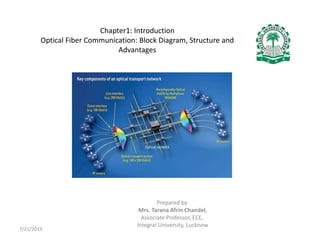
- 4. General View: Optical Communication System 7/21/2019 Prepared by Tarana Afrin Chandel, Associate Professor, ECE, IUL
- 5. Block Diagram: Optical Fiber Communication System 7/21/2019 Prepared by Tarana Afrin Chandel, Associate Professor, ECE, IUL
- 6. Optical fiber communication system consists • Transmitter • Regenerators • Receiver 7/21/2019 Prepared by Tarana Afrin Chandel, Associate Professor, ECE, IUL
- 7. Transmitter • Electric signal is applied to the optical transmitter • The optical transmitter consists of driver circuit, light source and fiber fly lead Driver circuit drives the light source Light source converts electrical signal to optical signal. Fiber fly lead is used to connect optical signal to optical fiber. 7/21/2019 Prepared by Tarana Afrin Chandel, Associate Professor, ECE, IUL
- 8. Transmission channel • Consists of a cable that provides mechanical and environmental protection to the optical fibers contained inside. • Each optical fiber acts as an individual channel. Optical splice is used to permanently join two individual optical fibers. Optical connector is for temporary non-fixed joints between two individual optical fibers. Optical coupler or splitter provides signal to other devices. 7/21/2019 Prepared by Tarana Afrin Chandel, Associate Professor, ECE, IUL
- 9. Regenerators • Repeater converts the optical signal into electrical signal using optical receiver • Passes to electronic circuit where it is reshaped and amplified as it gets attenuated and distorted with increasing distance • Because of scattering, absorption and dispersion in wave guides this signal is then again converted into optical signal by the optical transmitter. 7/21/2019 Prepared by Tarana Afrin Chandel, Associate Professor, ECE, IUL
- 10. Receiver • Optical signal is applied to the optical receiver. consists of photo detector, amplifier and signal restorer. • Photo detector converts the optical signal to electrical signal. 7/21/2019 Prepared by Tarana Afrin Chandel, Associate Professor, ECE, IUL
- 11. 7/21/2019 Prepared by Tarana Afrin Chandel, Associate Professor, ECE, IUL For short distance communication elements required are Source- LED Fiber- Multimode step index fiber Detector- PIN detector For long distance communication along with couplers, beam splitters, repeaters, optical amplifiers elements required are Source- LASER diode Fiber- single mode fiber Detector- Avalanche photo diode (APD)
- 12. Low Loss Optical Fiber • Optical fiber is a cable, known as cylindrical dielectric waveguide • Made of low loss material. • Considers the parameters such as environment in which it is operating, the tensile strength, durability and rigidity. • The Fiber optic cable is made of high quality extruded glass (si) or plastic, and it is flexible. • The diameter of the fiber optic cable is in between 0.25 to 0.5mm (slightly thicker than a human hair) • 7/21/2019 Prepared by Tarana Afrin Chandel, Associate Professor, ECE, IUL
- 13. Fiber Optic Cable 7/21/2019 Prepared by Tarana Afrin Chandel, Associate Professor, ECE, IUL
- 14. Parts of Fiber Optic Cable Core Cladding Buffer Jacket 7/21/2019 Prepared by Tarana Afrin Chandel, Associate Professor, ECE, IUL
- 15. Core • Core of a fiber cable is a cylinder • Coated with plastic to protect the cladding • Diameter of the core depends on the application used • Due to internal reflection, the light travelling within the core reflects from the core, the cladding boundary • The core cross section needs to be a circular 7/21/2019 Prepared by Tarana Afrin Chandel, Associate Professor, ECE, IUL
- 16. Cladding • Cladding is an outer optical material which protects the core • Main function of cladding : Reflects the light back into the core When light enters through the core into the cladding it changes its angle, and then reflects back to the core. 7/21/2019 Prepared by Tarana Afrin Chandel, Associate Professor, ECE, IUL
- 17. Buffer • Buffer is to protect the fiber from damage • Thousands of optical fibers are arranged in hundreds of optical cables • These bundles are protected by the cable’s outer covering that is called jacket 7/21/2019 Prepared by Tarana Afrin Chandel, Associate Professor, ECE, IUL
- 18. JACKET • Fiber optic cable’s jackets are available in different colors • Easily make us recognize the exact color of the cable we are dealing with • color yellow clearly signifies a single mode cable • orange color indicates multimode. 7/21/2019 Prepared by Tarana Afrin Chandel, Associate Professor, ECE, IUL
- 19. Advantage of Fiber Optics Immense bandwidth to utilize Total electrical isolation in the transmission medium Very low transmission loss, Small size and light weight, High signal security, Immunity to interference and crosstalk, Very low power consumption and wide scope of system expansion etc. 7/21/2019 Prepared by Tarana Afrin Chandel, Associate Professor, ECE, IUL
- 20. 7/21/2019 Prepared by Tarana Afrin Chandel, Associate Professor, ECE, IUL Thank you.