TrustArc Webinar - Unlock the Power of AI-Driven Data Discovery
13.6.1 Transformer Star Delta
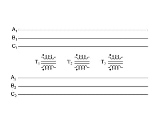
1. this phasing correct when the windings aren’t shown in regular Y or ∆
tricky. Let me illustrate, starting with Figure 10.42.
A1
B1
C1
T1 T2 T3
A2
B2
C2
42: Inputs A1 , A2 , A3 may be wired either “∆” or “Y”, as may outputs B1
dividual transformers are to be connected together to transform powe
2. Y-Y
A1
1º B1
C1
N1
T1 T2 T3
N2
A2
2º B
2
C2
A -A B-B C-C
3.
4.
5. Y-!
A1
B1
C1
N1
T1 T2 T3
A2
B2
C2
Figure 10.44: Phase wiring for “Y-∆” transformer.
6.
7. Y-!
A1
B1
C1
N1
T1 T2 T3
A2
B2
C2
Figure 10.44: Phase wiring for “Y-∆” transformer.
8. !-Y
A1
B1
C1
T1 T2 T3
N2
A2
B2
C2
Figure 10.45: Phase wiring for “∆-Y” transformer.
Such a configuration (Figure 10.45) would allow for the provision of multiple voltages (line-
to-line or line-to-neutral) in the second power system, from a source power system having no
neutral. “STAR”
And finally, we turn to the ∆-∆ configuration: (Figure 10.46)
When there is no need for a neutral conductor in the secondary power system, ∆-∆ connec-
tion schemes (Figure 10.46) are preferred because of the inherent reliability of the ∆ configu-
ration.
Considering that a ∆ configuration can operate satisfactorily missing one winding, some
power system designers choose to create a three-phase transformer bank with only two trans-
formers, representing a ∆-∆ configuration with a missing winding in both the primary and
secondary sides: (Figure 10.47)
This configuration is called “V” or “Open-∆.” Of course, each of the two transformers have
to be oversized to handle the same amount of power as three in a standard ∆ configuration,