Modeling stage rigging
•Download as DOCX, PDF•
0 likes•73 views

Just the method I like it. A Model rigging as shown above figure and mentioned in the Title: Please follow steps as mention IN THE ARTICAL

Recommended
More Related Content
What's hot
What's hot (19)
Similar to Modeling stage rigging
Similar to Modeling stage rigging (20)
Recently uploaded
Recently uploaded (20)
Modeling stage rigging
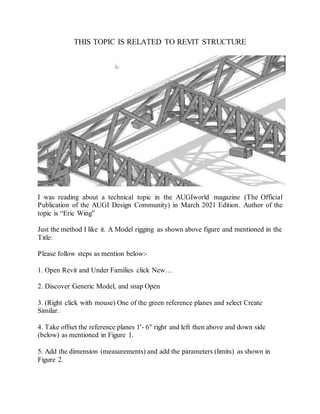
- 1. THIS TOPIC IS RELATED TO REVIT STRUCTURE I was reading about a technical topic in the AUGIworld magazine (The Official Publication of the AUGI Design Community) in March 2021 Edition. Author of the topic is “Eric Wing” Just the method I like it. A Model rigging as shown above figure and mentioned in the Title: Please follow steps as mention below:- 1. Open Revit and Under Families click New… 2. Discover Generic Model, and snap Open 3. (Right click with mouse) One of the green reference planes and select Create Similar. 4. Take offset the reference planes 1'- 6" right and left then above and down side (below) as mentioned in Figure 1. 5. Add the dimension (measurements) and add the parameters (limits) as shown in Figure 2.
- 2. 6. In the Project Browser, In the Elevations category (Elevation 1), select Left elevation. 7. Make a reference plane 3'- 0" over the Ref Level. 8. Dimension the Reference plane beginning from the level to the new reference plane 9. Add a parameter called Height. 10. Go back towards the Ref. Level floor plan and draw the reference planes, dimensions and parameters as shown in Figure 3.
- 3. ADDING A SOLID BLEND 1. Click the Blend button on the Forms Panel. 2. Select Pick Lines button and make assured the Lock button is checked 3. Pick the outer reference planes (That will be the bottom of the Blend) 4. Click Edit Top and pick the four reference planes on the Model Panel, which indicate the Peak. 5. Click the Green Check mark for close the Edit Mode 6. Go again to the Left elevation. 7. Align and lock the top of the blend to the top reference plane as shown in Figure 4.
- 4. 8. Go to the 3D view 9. Click the Sweep button in the “Create” Tab 10. Click the Pick Path 11. Select one of the four lines connecting the base to the top 12. Select the Green checkmark 13. Create a 2” Diameter circle and select the red dot on the middle of the line 14. Add a Diameter dimension (size) and label it Pipe Size as shown in Figure 5. 15. Repeat the same for the rest of the lines so there’s four pipes. 16. Choose (Select) the solid Blend and uncheck Visible in the properties 17. Save the family file as Truss Bars.rfa
- 5. LINE BASED FAMILIES In this part, we will model the real framework of our truss. Then, we load in the Truss Bars family and create an array which will be calculate the number and spacing of the bars. 1. Start with the new family using the template called Generic Model Line Based. 2. Click on the Sweep button. 3. Click or Select Sketch Path. 4. For the first point, click the most left intersection, for the second point, click on the right intersection. 5. Click the green check mark to finish. 6. Go to the Project Browser and select Left elevation 7. Click on Edit Profile 8. Add three 4” circles on the reference planes, dimensions and parameters as mentioned in Figure 6. 9. Click Green checkmark button to finish. 10. Again go to the Ref Level floor plan.
- 6. 11. In the properties bar, change Length to 10’-0”. 12. Go to Insert tab, then Load Family and choose your Truss Bars family 13. Select the Component button. 14. Press the space bar once to flip it as shown in Figure 7 15. Place it in the model roughly where shown, below to the left. 16. Align and lock the centerline of the family to the middle reference plane and left side of the family to the left reference plane, as shown below in Figure 7 to the right 17. Go to the Properties panel, select the Family Types button 18. Make the following parameter as shown below in Figure 8, make sure your settings are identical 19. Now make the following parameters (dimensions) as instance parameters, and the Type of Parameter as length. Also add the Values and Formulas as shown in Figure 9
- 7. 20. Select the Truss Bars family with mouse 21. Click the Edit Type 22. Click the Associate Family Parameter (Dimensions) along with the corresponding parameters you just made as shown in Figure 10
- 8. CREATING THE ARRAY Still we are discussing the Revit, how we will array our nested family. 1. Go to the Project Browser and select the Front Elevation 2. Click Array after selecting the Truss Bars Family in the Front Elevation 3. Number will be 2 in the options area and Move to: is 2nd 4. Click anywhere on the first family and pick a second point to the right about 4’. 5. Press Esc. Put a dimension from the center point of the first family to the center point of the second family as shown. 6. Select the dimension and add the Bar Spacing parameter to it as shown to the left below: 7. You will see a small number 2 when you select the family to the right. Select that, and add the parameter Number of Bars as Shown on the Right below Now you done the job! Load this family to the project and click on Component and start making drawing. Change the complete size parameters as needed. Any further assistance for this send an E-mail at ewing@cscos.com