Supplier Hoist Cranes Jakarta | stahlindo
•
0 likes•1,613 views

Stahlindo adalah supplier crane di jakarta

Recommended
Recommended
More Related Content
What's hot
What's hot (9)
Similar to Supplier Hoist Cranes Jakarta | stahlindo
Similar to Supplier Hoist Cranes Jakarta | stahlindo (20)
Recently uploaded
Recently uploaded (20)
Supplier Hoist Cranes Jakarta | stahlindo
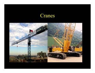
- 1. Cranes
- 2. Cranes Mobile Cranes • Mechanical or hydraulic types • Mechanical also referred to as “conventional” crane • Mechanical cranes have greater capacity • Hydraulic cranes have greater mobility and require less setup time
- 3. Cranes Mobile Cranes • Lattice boom or telescopic boom • Crane capacity is controlled by its operating radius • Operating radius is: – horizontal distance from center of rotation to the hook – a function of boom length and boom angle with the horizontal
- 4. Cranes Mobile Cranes • Other factors that influence capacity: – position of boom with respect to the carrier i.e.: over the front vs. over the rear or sides – amount and configuration of the counterweight – condition of the supporting surface – tire capacity (stationary and pick & carry)
- 5. Cranes Lifting Data • Crane manufacturers provide lifting data that includes: – Range diagram – Load rating charts – PCSA Rating Class – Miscellaneous notes and dimensions
- 6. Cranes Lifting Data • PCSA Rating Number – first number indicates the operating radius for nominal capacity – second number indicates the rated load (in hundreds of pounds) at a 40’ operating radius using a 50’ boom – all loads are taken in the direction of least stability with outriggers set – good way to compare apples with apples
- 7. Cranes Lifting Data • Load Rating Charts – lifting capacities based on ≤ 85% of tipping load on outriggers – lifting capacities based on ≤ 75% of tipping load on tires and crawlers – hook blocks, slings, spreaders, and other lifting devices are part of the load ∴include as part of the maximum safe load or deduct their weight to determine net load capacity
- 11. Tower Cranes • Heavy lifting for tall buildings • Max. unsupported height typically 265’ (80 m) • Much greater heights when supported by building’s framework
- 12. Tower Cranes • Max. reach 230’ (70 m) • Max. lift 19.8 Tons (18t) • Counter weight = 20 Tons • Maximum load-moment = 300 tonne-meter ex.: 30m (100’) radius yields a 10t lifting capacity • Limit switches for max. load & load-moment
- 13. Tower Cranes • Mast anchor-bolted to 30’ x 30’ x 4’ pad • Concrete pad weighs over 500,000#’s • Mast sections are typically 20’ x 10’ square
- 14. Tower Cranes • Slewing unit mounts at top of mast (tower) • Cat-head, jib, trolley, machinery arm, ties, & operator’s cab • Machinery arm contains motors, electronics, cable drum, and counter weight
- 15. Tower Cranes
- 16. Utility Construction • Underground vs. aerial • Public & private • Transmission, distribution, or service • Work sometimes performed on “live or hot” energized electric lines or pressurized water or gas lines.
- 17. Utility Construction Utilities include: • Electric - aerial or UG • Communication – Telephone, CATV, traffic and railroad signal • Water • Natural gas & petroleum • Sanitary sewer • Storm sewer & streams
- 18. Utility Construction Aerial Utilities -- Electric: • Supported on poles or towers • Electric cable – bare or insulated • Primary electric is 3-phase ranging from 12,000 volts to 500,000 volts • Current can jump to objects i.e. crane or excavator booms depending on the distance and relative humidity
- 19. Utility Construction Aerial Utilities - Electric: • Maintain a minimum 10’ distance between equipment and high voltage wire • Secondary electric is used to feed individual customers and street lighting • Service drops are 3-wire aerial connection from the street to the customers service head
- 20. Utility Construction Aerial Utilities- Electric: • Service can also be provided underground from a riser at the nearest pole • Service drop should have a drip loop to prevent water from entering service • Grounding of permanent and construction equipment is critical for safety
- 21. Utility Construction Aerial Utilities- Electric: • Towers should be grounded to drain induction charge • De-energized conductors should also be grounded • Pole lines are generally located within the R/W for public utilities • Line pole (unless they are end poles) usually do not require guying
- 22. Utility Construction Aerial Utilities: • Corner poles (even with modest breaks) require guying or stiff-backs • Down guys or aerial guys • Positioning of anchors is critical • Position on pole is primary, secondary, telephone, and CATV uy ire erialines ornerole etail
- 23. Utility Construction Underground Utilities: • A myriad of systems installed during various points in time • Some locations known, other not known • Urban environments have a high density of buried utilities • UG utilities add to the cost and risk of excavation
- 24. Utility Construction Underground Utilities: • Various codes stipulate clearances between the different utilities • New construction employees underground distribution to a great extent • New transmissions & distribution lines are often placed in utility corridors • Underground is generally much more expensive that aerial
- 25. Utility Construction Underground Utilities: • Electric and telephone cable can be: – Direct burial cable – Placed in metal or PVC conduit or ducts – Encased in concrete • Multiple cables run in duct banks • Conductors are insulated
- 26. Utility Construction Underground Utilities: • Depth of cover dictated by spec or NEC • Telephone cables are either copper or fiber optic. • Interruption of any service can be expensive, but telephone is the most costly • Splicing telephone cable is labor-intensive and time- consuming
- 27. Utility Construction Underground Utilities: • Cable can be installed by trenching • Conduit and pipe can be installed by open cut, trenching (small diameter), jacking, and directional boring • Splicing occurs in manholes, junction wells, pedestals, or CEV’s
- 28. Utility Construction Underground Utilities: • Natural gas transmission – high pressure; distribution – low pressure • Steel or plastic pipe • Cathodic protection system installed on steel pipe to deter corrosion • Pipe is often coated or wrapped in a mastic membrane
- 29. Utility Construction Underground Utilities: • Modern water distribution in ductile iron pipe (DIP) or PVC • Service piping: copper, PVC, polybutylene • Antiquated systems still in service include: galvanized steel, transite (asbestos cement), and even wood!
- 30. Utility Construction Underground Utilities: • Line valves provide isolation to portions of the main • Corporation stops are tapped directly into the main at each point of service • Curb stop is a valve at the property line
- 31. Utility Construction Underground Utilities: • Sanitary sewer is usually gravity flow but can also be forced (lift or ejector pump) • Modern pipe is DIP, PVC, or ABS • Old systems include terra cotta (clay), lead • Large systems may be concrete or brick structures
- 32. Utility Construction Underground Utilities: • Laterals leave building and tie into trunk line • Trunk lines tie into larger mains • Sewer lines intersect at manholes • Invert elevations are critical • Proper line and grade control is paramount • Bedding, placing, and backfilling sewer lines must be done correctly to prevent future settlement or displacement
- 33. Utility Construction Underground Utilities: • Storm sewer systems also depend on gravity for flow • Pipe includes RCP, CMP (galvanized steel or alum.), PVC/ABS/polyethylene • Culverts carry storm or stream flow
- 34. Utility Construction Underground Utilities: • Drainage structures include inlets or catch basins, manholes, junction boxes, and headwalls • Modern systems often included treatment systems such as “Bay Savers” (Refer to www.baysaver.com)
- 35. Utility Construction Utility Construction – UG Priority of Installation 1. Sanitary Sewer – deep, critical gravity flow 2. Storm Sewer – less critical gravity flow 3. Water – pressurized flow requiring installation below frost line 4. Gas – pressurized flow, minimum safe cover
- 36. Utility Construction Utility Construction – UG Priority of Installation 5. Electric – flexible installation requiring safe location 6. Telephone – more flexible than electric 7. CATV and other communication have lowest priority (usually posses least danger and expense to repair)
- 37. Utility Construction Utility Construction – UG Color Codes WATER NATURAL GAS ELECTRIC COMMUNICATIONS SANITARY SEWER YELLOW ORANGE RED GREEN BLUE
- 38. Utility Construction ……….trench incompatibility Sanitary Sewer Water Gas Electric
- 40. Manholes • Sanitary Sewer • Storm Drainage • Pump Station Wet Wells
- 41. Fittings • Bends • Saddle Tees
- 42. Gravity Pipe • Sewers • Storm Drainage • Roadway Culverts
- 43. Box Culverts • Storm Drainage • Roadway Culverts • Tunnels • Bridges
- 44. Preparation of Firm Bed 6” Minimum Granular Material
- 45. Form & Tie Steel for Floor
- 46. Set Up Form Work
- 47. Inside & Outside Forms
- 48. Set Box Sections
- 49. Immediate Backfill & Open Roadway
- 50. Placing hotmix pavement over culvert
- 56. Actual Installation Trenching Shield 4 inches 2 Ft2 Ft 2 Ft Initial density after compaction 95% After removing shield 82% Need the rigidity and strength of RCP to overcome the decrease in density
- 57. Construction Standards For Excavation (29 CFR Part 1926.650-.652) Subpart P • Applies to trenches – > 5’ ≤ 20’ deep – < 15’ wide at the base – exception = in only stable rock • 80% fatalities occur in trenches < 12’ • 30% occur in trenches < 8’
- 58. Construction Standards For Excavation (29 CFR Part 1926.650-.652) Subpart P • Requires a “Competent Person” be present on site and provide inspections: – daily – after every rainstorm – anytime conditions change
- 59. Construction Standards For Excavation • Inspecting for: – possible cave-ins – protection system failures – hazardous atmosphere – falling objects – enforcement of safety policy & procedures – any other hazards
- 60. Construction Standards For Excavation • Before you dig: – identify and locate all utilities – plan protection for workers for any active utilities that will be in the trench – determine if a hazardous atmosphere may exist in a trench > 4’ – plan evacuation routes out of trenches over 4’ within 25’ of workers
- 61. Trench Excavation Causes of Collapse • Soft zones • Layered soil • Sloughing • Vibration • Effects of water • Soft pockets • Old utility crossing trench • Fractured rock
- 62. Trench Excavation Soil Classification Class Solid Rock Class A Class B Class C Compressive Strength NA > 1.5 TSF (no vib/fis/lay) > 0.5 but < 1.5 TSF ≤ 0.5 TSF
- 63. Trench Excavation Soil Classification Visual • Grain size • Clumping • Tension cracks • Layering • Water • Vibration Manual • Plasticity test • Dry strength test • Thumb test • Drying test • Penetrometer
- 64. Trench Excavation Soil Classification Plasticity Test ……….Roll a “worm” 2” x 1/8” • If it does not work, the soil is non- cohesive Type B or C • If it works, the soil is cohesive Type A, B, or C depending on unconfined compressive strength
- 65. Trench Excavation Soil Classification Dry Strength • If the soil crumbles on its own, it is granular Type B or C • If it the soil is hard to break into clumps and unfissured, it is Type A
- 66. Trench Excavation Soil Classification Thumb Penetration (unconfined compressive strength) • Past the knuckle = Type C ≤ 0.5 TSF • To the knuckle = Type B > 0.5 but < 1.5 TSF • Just a dent = Type A . 1.5 TSP
- 67. Trench Excavation Sloping/Benching Options 1.5 : 1 Slope only (34 degrees) Bench or slope according to Appendices A & B Slope or bench according to Appendices A & B Designed by a Registered Professional Engineer, with a copy of the design on site
- 68. Trench Excavation Maximum Allowable Slope Stable Rock = Vertical 90° (to horizontal) Type A Soil = 3/4 : 1 53° (to horizontal) Type B Soil = 1 : 1 45° (to horizontal) Type C Soil = 1.5 : 1 34° (to horizontal)
- 69. Trench Excavation Shoring • Timber shoring must be properly designed using Table Data (Appendices A, C or other table), or by a Professional Engineer • Manufactured shoring must be installed according to Manufacturer’s specifications • Table Data not obtained from Appendix A or C must be kept on site
- 70. Trench Excavation Shielding • Trench boxes must be used according to the manufacturer’s specifications, or a PE • Must be maintained • Specifications must be kept on site
- 71. Trench Excavation Concerns During Trench Excavation • Placement of spoils (surcharge load) • Location of equipment and trucks • Diversion/control of water • Vehicular and pedestrian traffic • Adjacent buildings and other structures • Protection during off hours