Download to read offline
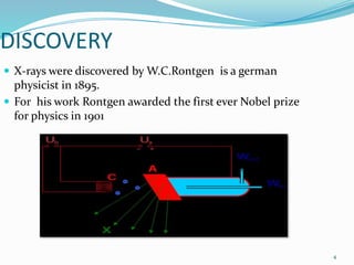
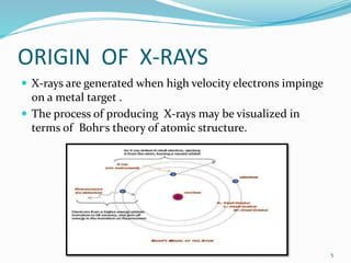
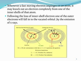
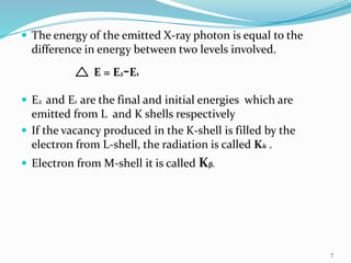
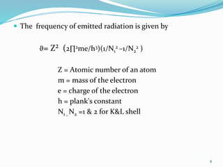
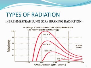
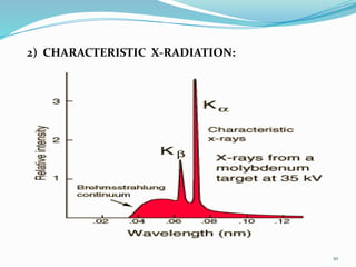
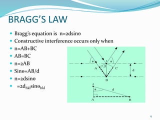


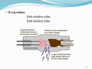
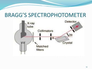
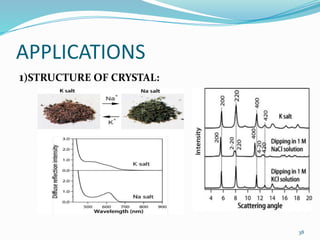
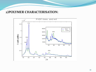


X-rays were discovered in 1895 by Wilhelm Röntgen. X-rays are produced when high velocity electrons hit a metal target, knocking electrons out of inner shells of atoms within the target. As outer electrons fall into these vacancies, characteristic X-rays are emitted with energies specific to the element. X-ray diffraction methods like Bragg's law are used to analyze crystal structures of materials by detecting the angles and intensities of diffracted X-ray beams. Common applications include determining structures of polymers, particle sizes, and states of materials.