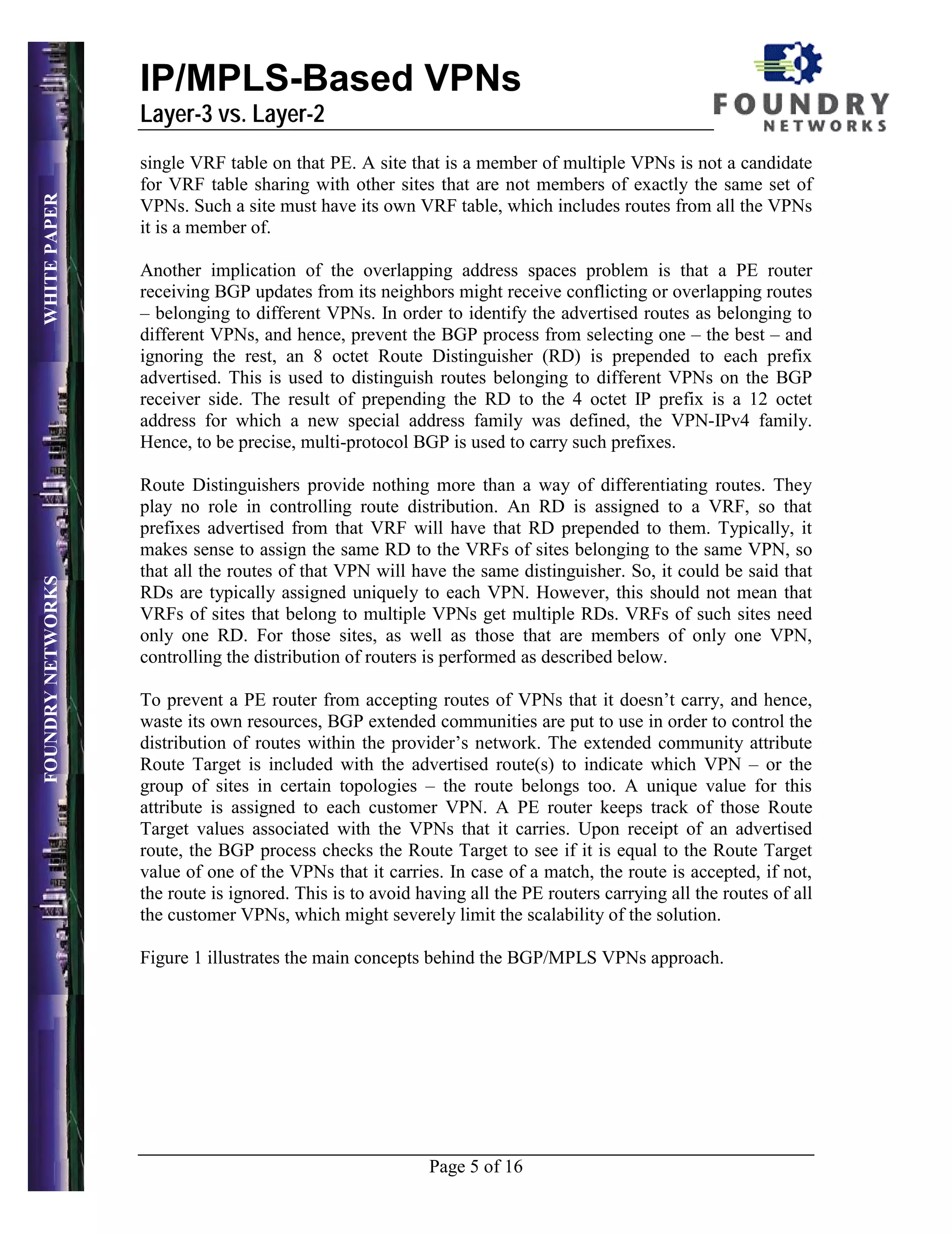
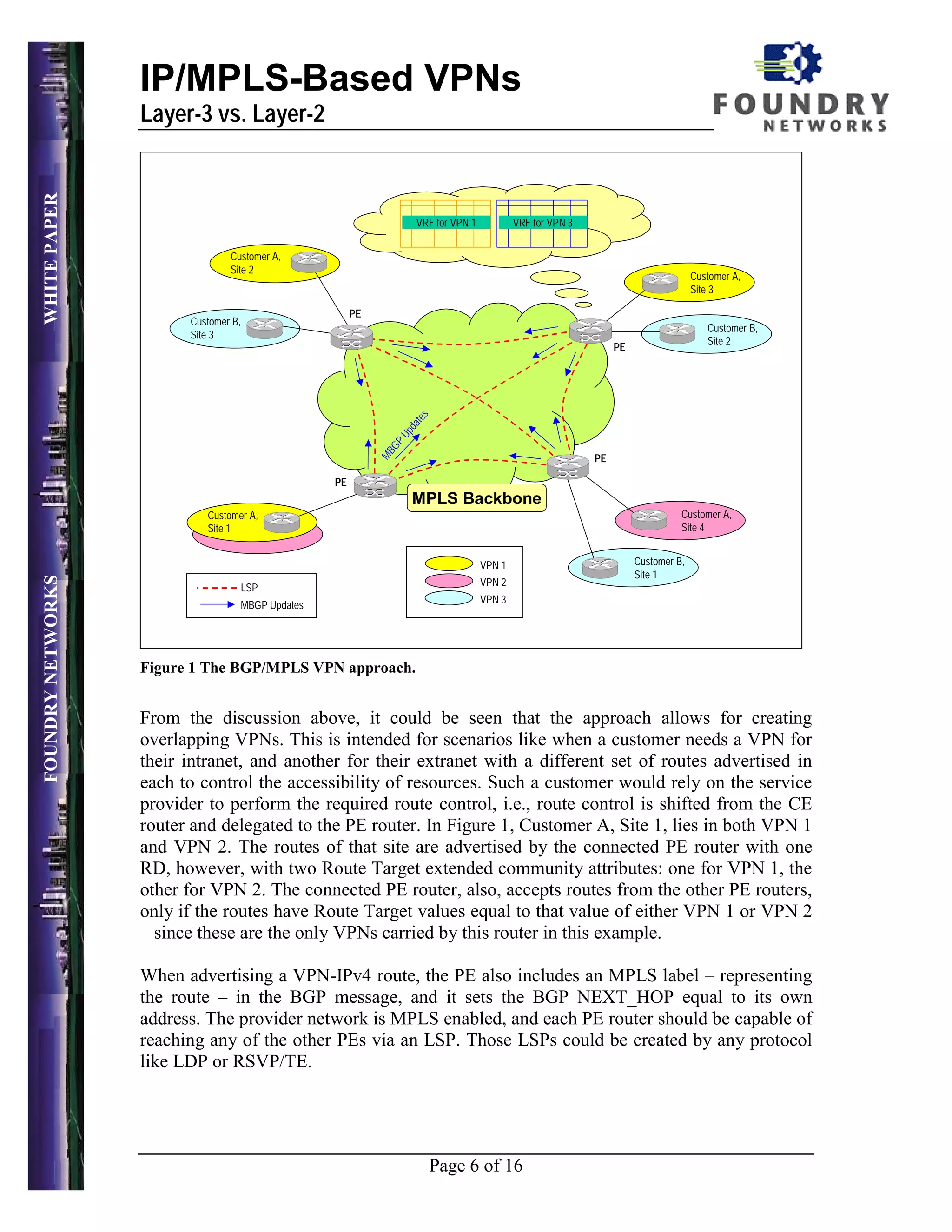
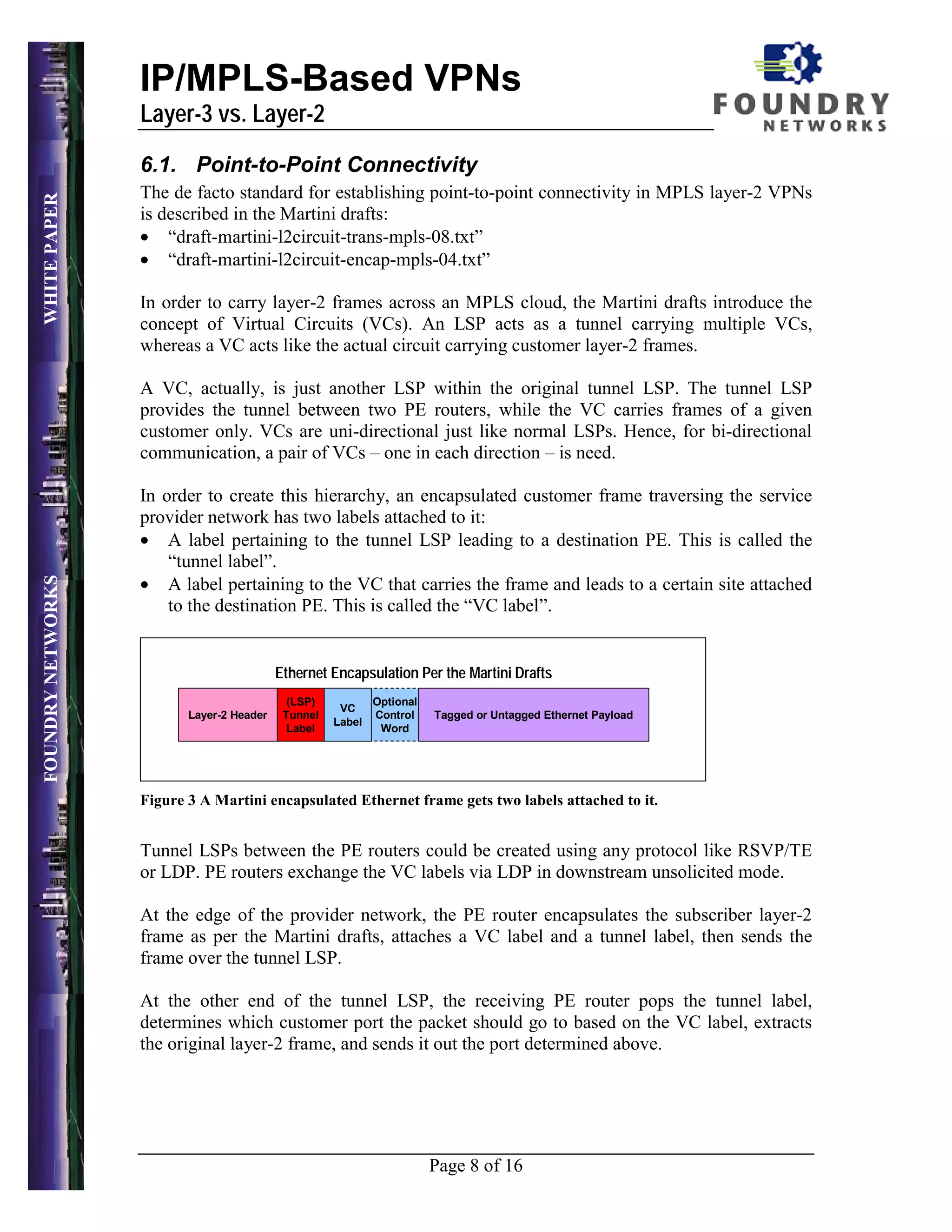
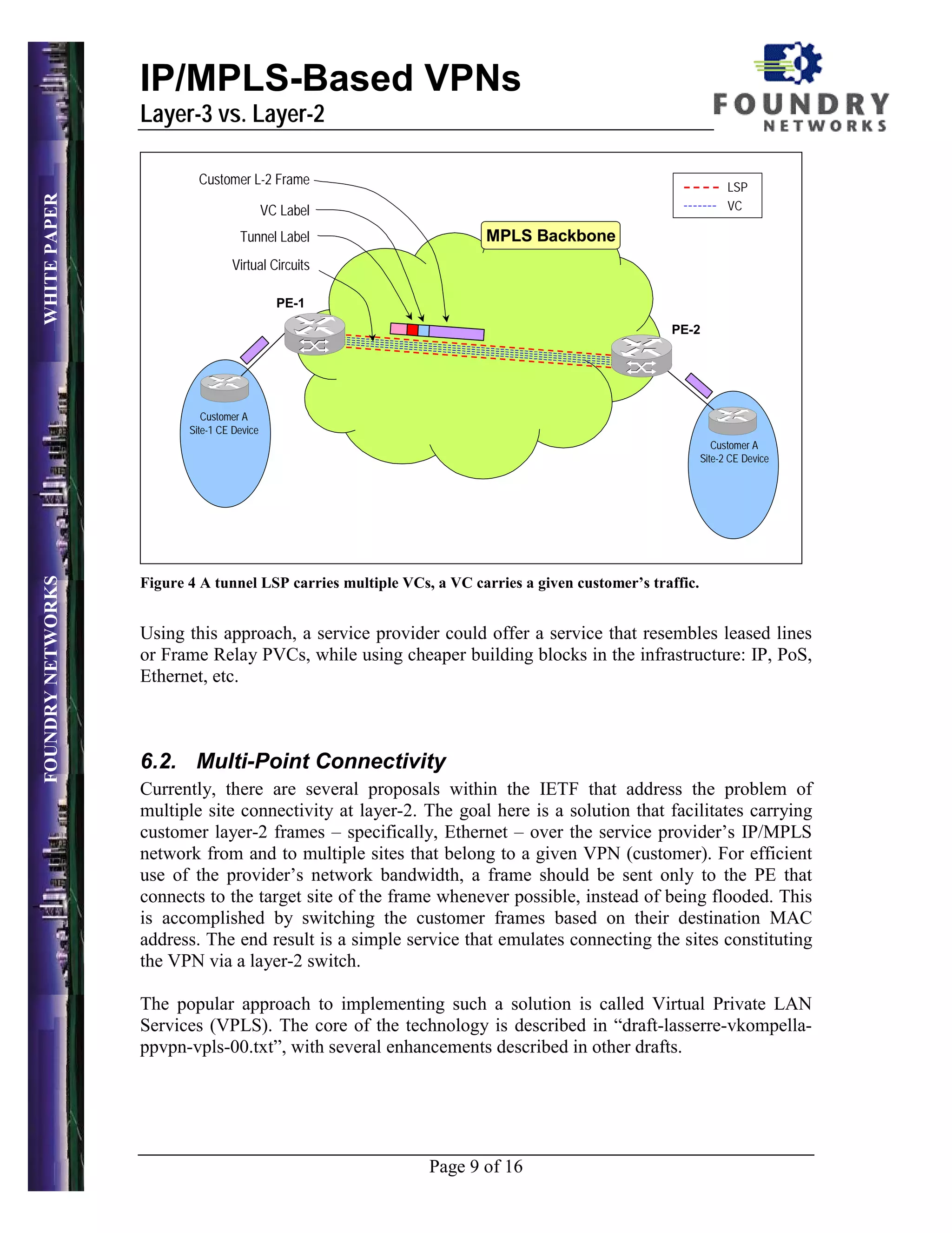
This document discusses and compares layer-3 and layer-2 approaches to implementing IP/MPLS-based VPNs. MPLS layer-3 VPNs use a routed approach defined in RFC 2547, where customer routes are exchanged between provider edge (PE) routers using BGP. MPLS layer-2 VPNs can provide point-to-point or multi-point connectivity using virtual circuits or virtual private LAN service. The document evaluates aspects of each approach like supported traffic, scalability, and complexity to help service providers determine the best fit for their network.
MPLS VPN provides a way to extend private network connectivity over a shared public infrastructure in a secure manner. It utilizes MPLS to create virtual point-to-point connections between customer sites. There are two main types of MPLS VPNs - Layer 3 VPNs which use extensions to BGP to exchange routing information between customer edge routers and provider edge routers, and Layer 2 VPNs which extend customer layer 2 networks across the MPLS backbone by encapsulating layer 2 frames with labels.
International Journal of Engineering Research and Development (IJERD)IJERD Editor
call for paper 2012, hard copy of journal, research paper publishing, where to publish research paper,
journal publishing, how to publish research paper, Call For research paper, international journal, publishing a paper, IJERD, journal of science and technology, how to get a research paper published, publishing a paper, publishing of journal, publishing of research paper, reserach and review articles, IJERD Journal, How to publish your research paper, publish research paper, open access engineering journal, Engineering journal, Mathemetics journal, Physics journal, Chemistry journal, Computer Engineering, Computer Science journal, how to submit your paper, peer reviw journal, indexed journal, reserach and review articles, engineering journal, www.ijerd.com, research journals,
yahoo journals, bing journals, International Journal of Engineering Research and Development, google journals, hard copy of journal
The document discusses QoS models and differentiated services model features. It provides an overview of MPLS QoS, including mapping IP precedence to MPLS experimental bits, supporting DiffServ over MPLS using E-LSPs and L-LSPs, and examples of configuring MPLS QoS on PE routers including classification, policy maps, and attaching policies to interfaces.
This document discusses different types of virtual private networks (VPNs) and their requirements. It describes four main types of VPNs: virtual leased lines, virtual private routed networks, virtual private LAN segments, and virtual private dial networks. For each type, it outlines their motivations, implementations, requirements around tunneling protocols, addressing, and quality of service guarantees. Further standardization is needed on a generic VPN identifier, membership configuration and dissemination, and addressing security and scalability issues.
this slide contains fundamental concept about VPLS protocol, according to the latest version of Cisco books and i taught it at IRAN TIC company.in the next slide, i upload attractive advanced feature about VPLS.
(Some of the pictures in this slide are borrowed from the wonderful site of my good friend Gokhan Kosem)
(www.ipcisco.com)
Auto-Bandwidth Allocation in Multicast Aware VPLS NetowrksAllan Kweli
The document summarizes a point-to-multipoint virtual private LAN service (VPLS) network testbed setup that uses auto-bandwidth allocation over MPLS traffic engineered tunnels. Key steps include:
1) Establishing pseudowires between provider edge routers using Border Gateway Protocol for auto-discovery and Label Distribution Protocol for signaling.
2) Configuring two VPLS instances on the provider edge routers to emulate LAN connectivity for different customer sites.
3) Creating MPLS-TE tunnels between provider edge routers using constraints-based routing and OSPF, which the pseudowires utilize.
4) Enabling auto-bandwidth allocation over the MPLS-TE tunnels to dynamically
The document discusses various transport layer protocols for mobile computing environments:
- Traditional TCP faces problems with high error rates and mobility-induced packet losses in wireless networks. It can lead to severe performance degradation.
- Indirect TCP segments the TCP connection and uses a specialized TCP for the wireless link, isolating wireless errors. But it loses end-to-end semantics.
- Snooping TCP buffers packets near the mobile host and performs local retransmissions transparently. But wireless errors can still propagate to the server.
- Mobile TCP splits the connection and uses different mechanisms on each segment. It chokes the sender window during disconnections to avoid retransmissions and slow starts. This maintains throughput during
This slide contains basic concept about MPLS and LDP protocol, according to the latest version of Cisco books(SP and R&S) and i taught it at IRAN TIC company.
i will prepare MPLS_VPN and MPLS_QoS and MPLS_TE later.
The document discusses various topics related to multicast routing including: 1) classification of multicast routing protocols based on path construction and maintenance, 2) optimized and overlay multicast routing approaches that bypass traditional deployment, and 3) challenges and approaches for multicast routing in mobile and inter-domain contexts.
This document discusses various approaches to improving TCP performance over mobile networks. It describes Indirect TCP, Snooping TCP, Mobile TCP, optimizations like fast retransmit/recovery and transmission freezing, and transaction-oriented TCP. Each approach is summarized in terms of its key mechanisms, advantages, and disadvantages. Overall, the document evaluates different ways TCP has been adapted to better support mobility and address challenges like frequent disconnections, packet losses during handovers, and high bit error rates over wireless links.
Fundamental of Quality of Service(QoS) Reza Farahani
This slide contains fundamental concept about Quality of Service (QoS) technolog, according to the latest version of Cisco books (CCIE R&S and CCIE SP) and i taught it at IRAN TIC company.In the next slide, i upload advanced topic about this attractive technology.
The document discusses several mechanisms used in TCP for mobile computing. It describes:
1) TCP congestion control mechanisms like slow-start and fast retransmit/fast recovery which are designed to address packet loss. However, these can be inappropriate for wireless networks where packet loss is often due to errors rather than congestion.
2) Approaches like Indirect TCP, Snooping TCP, and Mobile TCP which modify TCP for mobile networks by splitting connections or having a supervisory host monitor the connection to enable local retransmissions and avoid unnecessary window reductions when the mobile host disconnects.
3) Other TCP optimizations for mobile like forced fast retransmit after handovers and transmission timeout freezing to avoid slow-start
This document discusses bandwidth management and quality of service (QoS) in computer networks. It begins with a brief history of moving from circuit-switched to packet-switched networks. It then defines several key terms related to bandwidth management and QoS, including how they control network traffic to avoid congestion. The document goes on to explain specific bandwidth management techniques like leaky bucket and token bucket algorithms. It also discusses QoS mechanisms and how carrier Ethernet networks use bandwidth profiles and traffic management to provide differentiated services.
The document discusses various approaches to improving TCP performance over mobile networks. Indirect TCP splits the TCP connection at the foreign agent to isolate the wireless link. Snooping TCP has the foreign agent buffer packets and retransmit lost packets locally. Mobile TCP uses a supervisory host to monitor connections and choke the sender window during disconnections. Other techniques discussed include fast retransmit/recovery after handovers, freezing TCP states during interruptions, selective retransmission of only lost packets, and transaction-oriented TCP to reduce overhead of short messages. Each approach has advantages but also disadvantages related to compatibility, transparency, and complexity.
The document discusses Quality of Service (QoS) techniques used to prioritize certain types of network traffic over others. It covers QoS concepts like classification, marking, queuing, and congestion avoidance. It also provides examples of how to implement QoS in Cisco devices and deploy QoS enterprise-wide.
Mobile transport layer - traditional TCPVishal Tandel
This document summarizes several mechanisms proposed to improve TCP performance in wireless networks. It discusses approaches like indirect TCP, snooping TCP, and mobile TCP that split the TCP connection to isolate the wireless link. It also covers fast retransmit/recovery techniques, transmission freezing, and selective retransmission to more efficiently handle packet losses due to mobility. While each approach aims to address TCP issues in wireless networks, they often do so by mixing layers or requiring changes to the basic TCP protocol stack.
This document provides an overview of Quality of Service (QoS) in computer networks. It discusses several key IP QoS mechanisms including resource reservation using RSVP, admission control with bandwidth brokers, packet classification and marking, queuing disciplines like priority queuing and weighted fair queuing, traffic shaping using leaky bucket and token bucket algorithms, and policing. It also describes QoS frameworks like IntServ and DiffServ that systematically apply these mechanisms. Finally, it covers QoS in wireless networks, focusing on support in 802.11 networks and interactions with mobility protocols.
Quality of Service (QoS) is an important concept in any network which ultimately leads to network efficiency and customer satisfaction. In this PPT, we deal mainly with the Quality of Service aspects relating to Femto Access Point (FAP) of UMTS technology. PPT mainly deals with the Guaranteed Bit Rate (GBR) implementations.
This document provides an overview of quality of service (QoS) technologies for computer networks. It discusses two main QoS frameworks: Differentiated Services, which classifies traffic into groups and handles each group differently without resource reservation; and Integrated Services, which involves reserving resources for each session to guarantee performance levels. The document also compares the two frameworks and their approaches to service type, service scope, complexity, and scalability.
IP Multicast Routing Part One.
Concepts explained inside are : Internet Multicast Backbone, Multicast Addressing and Mapping, Multicast: How it works, IGMP v1,v2,v3 and more.
Note: All slides care of a more detailed explanation about the concepts involved. If you need just that, send me a message and I'll reply with a pdf document with just that. All explanations are in English or/and Portuguese.
Thanks, Pedro Almeida.
MPLS Traffic Engineering provides mechanisms to optimize network traffic flow and efficiently utilize bandwidth. It determines paths based on additional parameters like available resources and constraints. This allows load balancing across unequal paths and routing around failed links or nodes. MPLS TE uses extensions to IGPs to distribute link attributes and tunnel information. Constrained Shortest Path First (CSPF) is used for path computation to find paths meeting constraints like bandwidth and affinities. Tunnels are set up using RSVP-TE and traffic can be forwarded down tunnels using methods like static routes, auto-routing, or policy routing. Fast Re-Route provides local repair of TE tunnels if a link or node fails to minimize traffic loss.
This document provides an overview of Multi-Protocol Label Switching (MPLS) technology. It discusses MPLS fundamentals, components, operations, applications for traffic engineering, virtual private networks, and any transport over MPLS. It also outlines topics like MPLS label distribution, virtual private network models, and future developments in MPLS. The document is intended to guide readers on key concepts in MPLS and provide background for further study.
PLNOG15: BGP New Advanced Features - Piotr WojciechowskiPROIDEA
This document provides an overview of new advanced BGP features including BGP Graceful Shutdown, BGP Additional Paths, support for multiple sourced paths per redistributed route, BGP Accumulated IGP Metric, and BGP FlowSpec. It describes each feature, how it works, and its configuration. The presenter is a senior network engineer and CCIE with experience designing networks and leading a large Cisco community.
LDP allows MPLS routers to exchange label mapping information by establishing LDP sessions between peers. LDP defines procedures and messages for routers to advertise label bindings and establish label switched paths for forwarding traffic. LDP sessions can be directly connected over a single hop or nondirectly connected over multiple hops using targeted Hellos.
This document discusses multicast routing protocols. It introduces concepts like multicast trees, reverse path forwarding, and describes several multicast routing protocols including DVMRP, MOSPF, CBT, PIM, and MBONE. DVMRP uses reverse path forwarding and pruning/grafting to efficiently route multicast traffic to multiple receivers. PIM comes in two variants - PIM-DM for dense networks and PIM-SM for sparser wide area networks. MBONE enables multicast routing over the Internet using logical tunneling between multicast routers.
The document discusses various approaches to modifying TCP for use in mobile networks. Indirect TCP splits the TCP connection at the foreign agent, keeping the fixed network unchanged but losing end-to-end semantics. Snooping TCP has the foreign agent snoop packets and retransmit lost packets locally without changing TCP. Mobile TCP uses a supervisory host to monitor disconnections and choke senders. Other approaches include forced fast retransmit after handovers, freezing TCP timers during disconnects, selective retransmission of only lost packets, and transaction-oriented TCP to combine connection setup in fewer packets. Each approach has advantages like efficiency or compatibility but also disadvantages like overhead or non-transparency.
Weighted fair queuing and RSVP are technologies that can help improve the transport of time sensitive traffic like voice and video across networks with limited bandwidth. The document describes how weighted fair queuing prioritizes traffic by separating it into parallel queues and giving some queues higher priority. RSVP allows endpoints to reserve bandwidth for applications by identifying traffic streams so routers can give them priority. The author tests these technologies on their network and finds that using weighted fair queuing and RSVP improves the quality of their LiveLAN video conferencing sessions during periods of network congestion.
This document lists TCP and UDP ports along with their descriptions and status. It provides information on common ports used for protocols like HTTP, DNS, SSH, SMTP, and more. The status is categorized as official, unofficial, or multiple use to indicate if the port is registered with IANA for a specific application, not registered, or can be used by multiple applications.
Transport Layer Port or TCP/IP & UDP PortNetwax Lab
A port is an application-specific or process-specific software construct serving as a communications
endpoint in a computer's host operating system. The purpose of ports is to uniquely identify different
applications or processes running on a single computer and thereby enable them to share a single
physical connection to a packet-switched network like the Internet. In the context of the Internet
Protocol, a port is associated with an IP address of the host, as well as the type of protocol used for
communication.
Quality of service aims to provide different levels of priority to different applications, users, or data flows. It is achieved through techniques like scheduling, traffic shaping, resource reservation, and admission control. Scheduling methods include FIFO queuing, priority queuing, and weighted fair queuing. Traffic shaping uses leaky bucket and token bucket algorithms. Resource reservation reserves buffer space, bandwidth, and other resources beforehand. Admission control restricts packet admission based on specifications. Models for QoS include the Integrated Services Model, which requires resource reservation in advance using RSVP, and the Differentiated Services Model, which differentiates traffic into classes.
Microsoft PowerPoint - WirelessCluster_PresVideoguy
This document analyzes delays in unicast video streaming over IEEE 802.11 WLAN networks. It describes conducting an experiment using a testbed with a Darwin Streaming Server and WLAN probe to capture packets. The analysis found that video bitrate variations, packetization scheme, bandwidth load, and frame-based nature of video all impacted mean delay. Bursts of packets from video frames caused per-packet delay to increase in a sawtooth pattern. Increasing uplink load was also found to affect delay variations.
This paper proposes an adaptive energy management policy for wireless video streaming between a battery-powered client and server. It models the energy consumption of the server and client based on factors like CPU frequency, transmission power, and channel bandwidth. The paper formulates an optimization problem to assign optimal energy to each video frame. This maximizes system lifetime while meeting a minimum video quality requirement. Experimental results show the proposed policy increases overall system lifetime by 20% on average.
Overview of the MPLS backbone transmission technology.
MPLS (MultiProtocol Layer Switching) is a layer 2.5 technology that combines the virtues of IP routing and fast layer 2 packet switching.
IP packet forwarding is not suited for high-speed forwarding due to the need to evaluate multiple routes for each IP packet in order to find the optimal route, i.e. the route with the longest prefix match.
However, Internet Protocol routing provides global reachability through the IP address and through IP routing protocols like BGP or OSPF.
Layer 2 packet switching has complementary characteristics in that it does not provide global reachability through globally unique addresses but allows fast packet forwarding in hardware through the use of small and direct layer 2 lookup addresses.
MPLS combines IP routing and layer 2 switching by establishing layer 2 forwarding paths based on routes received through IP routing protocols like BGP or OSPF.
Thus the control plane of an MPLS capable device establishes layer 2 forwarding paths while the data plane then performs packet forwarding, often in hardware.
MPLS is not a layer 2 technology itself, i.e. it does not define a layer 2 protocol but rather makes use of existing layer 2 technologies like Ethernet, ATM or Frame Relay.
1) The document defines several types of VPNs including IP-VPN, network-based IP-VPN, VLL, VPDN, VPLS, and VPRN. 2) MPLS VPN uses MPLS to create private networks over a public IP network. It establishes VPNs by using tunneling protocols and assigning unique routing identifiers to each VPN. 3) MPLS VPN provides isolation and security for each VPN by maintaining separate forwarding tables and using route distinguishers, route targets, and MPLS labels to direct traffic to the correct VPNs.
The document discusses MPLS VPN configurations. It covers VPN concepts like overlay and peer models, benefits of MPLS VPNs, and how routing information is propagated between provider edge (PE) routers using MP-BGP. Key aspects include using virtual routing and forwarding (VRF) instances to isolate customer routes, extending prefixes with route distinguishers (RDs) to handle overlapping addresses, and exchanging VPN routes between PE routers in the provider network.
MPLS enables service providers to create virtual private networks for customers by applying labels to packets and forwarding them through MPLS tunnels based on the label. This allows separation of customer traffic, improves routing performance, and enables both layer 2 and layer 3 services across wide areas.
This document discusses different types of virtual private networks (VPNs) and their requirements. It describes four main types of VPNs: virtual leased lines, virtual private routed networks, virtual private LAN segments, and virtual private dial networks. For each type, it covers definitions, benefits, issues that need to be addressed, and recommendations. Overall recommendations include further standardizing a generic VPN tunneling protocol, VPN membership configuration and dissemination, and addressing security and scalability challenges in supporting quality of service guarantees for VPNs.
This document describes an ISP core routing topology project that was implemented to demonstrate how a company accesses its servers through the internet. The key features of the project include MPLS Layer 3 VPN, an IPv6 network with an IPv6 DNS server, various redundancy protocols like HSRP, VRRP and GLBP, dynamic routing protocols such as BGP, EIGRP and OSPF, and a Linux server providing services like DNS, Apache, FTP and SSH. MPLS is used to eliminate delays and provide a VPN connecting different company branches. The topology also features an IPv6 tunnel over an IPv4 network and dual stacking for IPv6/IPv4 communication.
Cube2012 high capacity service provider design using gpmls for ip next genera...Ashish Tanwer
The document discusses the design of a high capacity service provider network using Generalized Multiprotocol Label Switching (GMPLS) for next generation IP networks. It outlines the internal architecture of the service provider including the use of BGP confederations, virtual routing and forwarding instances (VRFs), route targets, and route distinguishers to optimize routing. It also describes different GMPLS topology models and considers hardware designs from Cisco, Juniper, and Ciena to support latest protocols, security, and scalability.
MPLS L3 VPN allows companies to offer Layer 3 VPN services with advantages like scalability, security, and support for duplicate IP addresses and different network topologies. The key components that enable this are VRF tables on PE routers that separate routing information for each customer to avoid duplicate IP issues, and MP-BGP which customizes VPN routing information using a Route Distinguisher, VPN label, and Route Target to support different VPN topologies. MPLS L3 VPN provides services like multi-homed sites for redundancy, hub-and-spoke networks, internet access with security, and extranets for inter-company communication.
VRF (Virtual Routing and Forwarding) is a technology that allows multiple instances of a routing table to
co-exist within the same router at the same time. This increases functionality by allowing network paths
to be segmented without using multiple devices. Because traffic is automatically segregated, VRF also
increases network security and can eliminate the need for encryption and authentication. Internet
service providers (ISPs) often take advantage of VRF to create separate virtual private networks (VPNs)
for customers; thus the technology is also referred to as VPN routing and forwarding. Because the
routing instances are independent, the same or overlapping IP addresses can be used without
conflicting with each other.
This document discusses MPLS VPN and its three main types: point-to-point VPNs using pseudowires to encapsulate traffic between two sites; layer 2 VPNs called VPLS that provide switched VLAN services across sites; and layer 3 VPNs known as VPRN that utilize VRF tables to segment routing for each customer using BGP. It describes how MPLS VPN works using CE, PE, and P routers to forward labeled packets through the provider network and pop the label at the destination PE to deliver the packet. Finally, it provides additional resources for learning more about MPLS VPN technologies.
Interconnecting Neutron and Network Operators' BGP VPNsThomas Morin
joint presentation given at OpenStack summit Barcelona (Oct. 2016) with Paul Carver and Tim Irnich
talk video: https://www.youtube.com/watch?v=LCDeR7MwTzE
demo: https://www.youtube.com/watch?v=5iRoZcmQyuU
This lesson describes the concept of VPN and introduces some VPN terminology.
Importance
This lesson is the foundation lesson for the MPLS VPN Curriculum.
Objectives
Upon completion of this lesson, the learner will be able to perform the following
tasks:
■ Describe the concept of VPN
■ Explain VPN terminology as defined by MPLS VPN architecture
Flexible NFV WAN interconnections with Neutron BGP VPNThomas Morin
[talk given during the OpenStack Summit, May 2018 in Vancouver, BC]
Telcos use OpenStack to deploy virtualized network functions, and have specific requirements to interconnect these OpenStack deployments to their backbones and mobile backhaul networks. These interconnections, in particular, need to involve dynamic routing and interconnections with operators internal VPNs.
This talk will explain the role that the networking-bgpvpn Neutron Stadium project plays to address this need, from the basics of the BGPVPN Interconnection API, to more advanced uses made possible by evolutions of this API delivered in Queens.
The more interesting use cases will be the opportunity for a step by step demo.
We'll give a status of where the project stands today in terms of feature coverage, look at the set of SDN controllers providing an implementation for this API beyond the implementation in reference drivers, and last, look at the future of the project.
Virtual private networks (VPNs) allow private connectivity between networks over public infrastructure like the internet. A VPN uses tunneling protocols to encapsulate private network traffic within public network packets. Virtual private routed networks (VPRNs) are a type of layer 3 IP-based VPN that emulate a multi-site private network using virtual routing and forwarding tables on provider edge routers. The virtual router model implements VPRNs by running separate routing protocol instances for each VPN to exchange reachability information between customer edge routers via provider edge routers.
This document discusses implementing a virtual private network (VPN) over multi-protocol label switching (MPLS). It begins with an introduction to MPLS and how it works using label switching to route packets. It then discusses VPNs and how MPLS VPNs use separate routing tables called virtual routing and forwarding tables to isolate customer networks. The document demonstrates configuring an MPLS VPN using the GNS3 network simulator with two customer edge routers connecting two customer sites over an MPLS provider network. MPLS, VPNs, and the specific configuration steps are described. In the results section, the routing tables of the customer edge routers are shown to have routes from both customer sites, demonstrating that the MPLS VPN was successfully implemented to connect
VPNs, Tunneling, and Overlay Networks
Virtual private networks (VPNs) allow private networks to be extended over public networks like the internet. VPNs provide benefits like extended communication, reduced costs, and improved productivity. There are two main types of VPNs: remote-access VPNs which connect users to a private network from various locations, and site-to-site VPNs which connect organizations' remote sites into a private network or allow organizations to share environments. Tunneling protocols like PPP and protocols like IPsec are used to securely encapsulate and transmit data across VPNs. Multiprotocol Label Switching (MPLS) and overlay networks are additional methods to improve network performance and security.
The document discusses MPLS VPN and class of service capabilities for meeting demands on corporate networks. MPLS VPN uses label switching to create private networks over shared infrastructure. It allows flexibility, scalability, security and quality of service. Class of service differentiation and traffic prioritization help optimize application performance for voice, video and data.
Implementation of intelligent wide area network(wan)Jatin Singh
This project implements an intelligent wide area network (WAN) using several routing protocols and technologies. It uses Border Gateway Protocol (BGP) for routing between autonomous systems, Enhanced Interior Gateway Routing Protocol (EIGRP) for interior routing, and Multi-Protocol Label Switching (MPLS) to improve routing performance. It also implements Dynamic Multipoint VPN (DMVPN) to provide secure remote connectivity between sites using a hub-and-spoke topology in a scalable and economical way. The combination of these protocols and technologies enhances routing capabilities, improves traffic engineering, and enables secure virtual private networking across the intelligent WAN.
Interautonomous System PLS VPN Advanced ConceptsBrozaa
- The document discusses routing and traffic engineering techniques for inter-autonomous system MPLS VPNs. It describes using route reflectors to exchange routes between sub-autonomous systems and using next-hop-self to modify next-hop attributes. It also covers scaling inter-AS routing with techniques like automatic route filtering and inbound route filtering. Additional topics include downstream route target allocation for filtering, load balancing traffic across multiple inter-AS links, and using redundant PE-ASBR routers.
The document discusses Virtual Private Routed Network (VPRN) services. VPRNs use BGP and MPLS to provide Layer 3 VPN connectivity between customer sites. Each VPRN has its own routing table maintained by provider edge (PE) routers. PE routers exchange routes for each VPRN using MP-BGP. Routes include a Route Distinguisher to identify the VPRN. Tunnels using MPLS or GRE carry customer traffic across the provider network to the correct PE router based on the route label. The document outlines requirements, protocols, and features used to implement VPRNs such as route reflectors, route redistribution, and CE connectivity checks.
This lesson describes the concept of VPN and introduces some VPN terminology.
Importance
This lesson is the foundation lesson for the MPLS VPN Curriculum.
Objectives
Upon completion of this lesson, the learner will be able to perform the following
tasks:
■ Describe the concept of VPN
■ Explain VPN terminology as defined by MPLS VPN architecture
Essentials of Automations: Exploring Attributes & Automation ParametersSafe Software
Building automations in FME Flow can save time, money, and help businesses scale by eliminating data silos and providing data to stakeholders in real-time. One essential component to orchestrating complex automations is the use of attributes & automation parameters (both formerly known as “keys”). In fact, it’s unlikely you’ll ever build an Automation without using these components, but what exactly are they?
Attributes & automation parameters enable the automation author to pass data values from one automation component to the next. During this webinar, our FME Flow Specialists will cover leveraging the three types of these output attributes & parameters in FME Flow: Event, Custom, and Automation. As a bonus, they’ll also be making use of the Split-Merge Block functionality.
You’ll leave this webinar with a better understanding of how to maximize the potential of automations by making use of attributes & automation parameters, with the ultimate goal of setting your enterprise integration workflows up on autopilot.
[OReilly Superstream] Occupy the Space: A grassroots guide to engineering (an...Jason Yip
The typical problem in product engineering is not bad strategy, so much as “no strategy”. This leads to confusion, lack of motivation, and incoherent action. The next time you look for a strategy and find an empty space, instead of waiting for it to be filled, I will show you how to fill it in yourself. If you’re wrong, it forces a correction. If you’re right, it helps create focus. I’ll share how I’ve approached this in the past, both what works and lessons for what didn’t work so well.
Northern Engraving | Nameplate Manufacturing Process - 2024Northern Engraving
Manufacturing custom quality metal nameplates and badges involves several standard operations. Processes include sheet prep, lithography, screening, coating, punch press and inspection. All decoration is completed in the flat sheet with adhesive and tooling operations following. The possibilities for creating unique durable nameplates are endless. How will you create your brand identity? We can help!
The Department of Veteran Affairs (VA) invited Taylor Paschal, Knowledge & Information Management Consultant at Enterprise Knowledge, to speak at a Knowledge Management Lunch and Learn hosted on June 12, 2024. All Office of Administration staff were invited to attend and received professional development credit for participating in the voluntary event.
The objectives of the Lunch and Learn presentation were to:
- Review what KM ‘is’ and ‘isn’t’
- Understand the value of KM and the benefits of engaging
- Define and reflect on your “what’s in it for me?”
- Share actionable ways you can participate in Knowledge - - Capture & Transfer
QR Secure: A Hybrid Approach Using Machine Learning and Security Validation F...AlexanderRichford
QR Secure: A Hybrid Approach Using Machine Learning and Security Validation Functions to Prevent Interaction with Malicious QR Codes.
Aim of the Study: The goal of this research was to develop a robust hybrid approach for identifying malicious and insecure URLs derived from QR codes, ensuring safe interactions.
This is achieved through:
Machine Learning Model: Predicts the likelihood of a URL being malicious.
Security Validation Functions: Ensures the derived URL has a valid certificate and proper URL format.
This innovative blend of technology aims to enhance cybersecurity measures and protect users from potential threats hidden within QR codes 🖥 🔒
This study was my first introduction to using ML which has shown me the immense potential of ML in creating more secure digital environments!
Connector Corner: Seamlessly power UiPath Apps, GenAI with prebuilt connectorsDianaGray10
Join us to learn how UiPath Apps can directly and easily interact with prebuilt connectors via Integration Service--including Salesforce, ServiceNow, Open GenAI, and more.
The best part is you can achieve this without building a custom workflow! Say goodbye to the hassle of using separate automations to call APIs. By seamlessly integrating within App Studio, you can now easily streamline your workflow, while gaining direct access to our Connector Catalog of popular applications.
We’ll discuss and demo the benefits of UiPath Apps and connectors including:
Creating a compelling user experience for any software, without the limitations of APIs.
Accelerating the app creation process, saving time and effort
Enjoying high-performance CRUD (create, read, update, delete) operations, for
seamless data management.
Speakers:
Russell Alfeche, Technology Leader, RPA at qBotic and UiPath MVP
Charlie Greenberg, host
"Frontline Battles with DDoS: Best practices and Lessons Learned", Igor IvaniukFwdays
At this talk we will discuss DDoS protection tools and best practices, discuss network architectures and what AWS has to offer. Also, we will look into one of the largest DDoS attacks on Ukrainian infrastructure that happened in February 2022. We'll see, what techniques helped to keep the web resources available for Ukrainians and how AWS improved DDoS protection for all customers based on Ukraine experience
In the realm of cybersecurity, offensive security practices act as a critical shield. By simulating real-world attacks in a controlled environment, these techniques expose vulnerabilities before malicious actors can exploit them. This proactive approach allows manufacturers to identify and fix weaknesses, significantly enhancing system security.
This presentation delves into the development of a system designed to mimic Galileo's Open Service signal using software-defined radio (SDR) technology. We'll begin with a foundational overview of both Global Navigation Satellite Systems (GNSS) and the intricacies of digital signal processing.
The presentation culminates in a live demonstration. We'll showcase the manipulation of Galileo's Open Service pilot signal, simulating an attack on various software and hardware systems. This practical demonstration serves to highlight the potential consequences of unaddressed vulnerabilities, emphasizing the importance of offensive security practices in safeguarding critical infrastructure.
What is an RPA CoE? Session 1 – CoE VisionDianaGray10
In the first session, we will review the organization's vision and how this has an impact on the COE Structure.
Topics covered:
• The role of a steering committee
• How do the organization’s priorities determine CoE Structure?
Speaker:
Chris Bolin, Senior Intelligent Automation Architect Anika Systems
LF Energy Webinar: Carbon Data Specifications: Mechanisms to Improve Data Acc...DanBrown980551
This LF Energy webinar took place June 20, 2024. It featured:
-Alex Thornton, LF Energy
-Hallie Cramer, Google
-Daniel Roesler, UtilityAPI
-Henry Richardson, WattTime
In response to the urgency and scale required to effectively address climate change, open source solutions offer significant potential for driving innovation and progress. Currently, there is a growing demand for standardization and interoperability in energy data and modeling. Open source standards and specifications within the energy sector can also alleviate challenges associated with data fragmentation, transparency, and accessibility. At the same time, it is crucial to consider privacy and security concerns throughout the development of open source platforms.
This webinar will delve into the motivations behind establishing LF Energy’s Carbon Data Specification Consortium. It will provide an overview of the draft specifications and the ongoing progress made by the respective working groups.
Three primary specifications will be discussed:
-Discovery and client registration, emphasizing transparent processes and secure and private access
-Customer data, centering around customer tariffs, bills, energy usage, and full consumption disclosure
-Power systems data, focusing on grid data, inclusive of transmission and distribution networks, generation, intergrid power flows, and market settlement data
From Natural Language to Structured Solr Queries using LLMsSease
This talk draws on experimentation to enable AI applications with Solr. One important use case is to use AI for better accessibility and discoverability of the data: while User eXperience techniques, lexical search improvements, and data harmonization can take organizations to a good level of accessibility, a structural (or “cognitive” gap) remains between the data user needs and the data producer constraints.
That is where AI – and most importantly, Natural Language Processing and Large Language Model techniques – could make a difference. This natural language, conversational engine could facilitate access and usage of the data leveraging the semantics of any data source.
The objective of the presentation is to propose a technical approach and a way forward to achieve this goal.
The key concept is to enable users to express their search queries in natural language, which the LLM then enriches, interprets, and translates into structured queries based on the Solr index’s metadata.
This approach leverages the LLM’s ability to understand the nuances of natural language and the structure of documents within Apache Solr.
The LLM acts as an intermediary agent, offering a transparent experience to users automatically and potentially uncovering relevant documents that conventional search methods might overlook. The presentation will include the results of this experimental work, lessons learned, best practices, and the scope of future work that should improve the approach and make it production-ready.
"What does it really mean for your system to be available, or how to define w...Fwdays
We will talk about system monitoring from a few different angles. We will start by covering the basics, then discuss SLOs, how to define them, and why understanding the business well is crucial for success in this exercise.
Introducing BoxLang : A new JVM language for productivity and modularity!Ortus Solutions, Corp
Just like life, our code must adapt to the ever changing world we live in. From one day coding for the web, to the next for our tablets or APIs or for running serverless applications. Multi-runtime development is the future of coding, the future is to be dynamic. Let us introduce you to BoxLang.
Dynamic. Modular. Productive.
BoxLang redefines development with its dynamic nature, empowering developers to craft expressive and functional code effortlessly. Its modular architecture prioritizes flexibility, allowing for seamless integration into existing ecosystems.
Interoperability at its Core
With 100% interoperability with Java, BoxLang seamlessly bridges the gap between traditional and modern development paradigms, unlocking new possibilities for innovation and collaboration.
Multi-Runtime
From the tiny 2m operating system binary to running on our pure Java web server, CommandBox, Jakarta EE, AWS Lambda, Microsoft Functions, Web Assembly, Android and more. BoxLang has been designed to enhance and adapt according to it's runnable runtime.
The Fusion of Modernity and Tradition
Experience the fusion of modern features inspired by CFML, Node, Ruby, Kotlin, Java, and Clojure, combined with the familiarity of Java bytecode compilation, making BoxLang a language of choice for forward-thinking developers.
Empowering Transition with Transpiler Support
Transitioning from CFML to BoxLang is seamless with our JIT transpiler, facilitating smooth migration and preserving existing code investments.
Unlocking Creativity with IDE Tools
Unleash your creativity with powerful IDE tools tailored for BoxLang, providing an intuitive development experience and streamlining your workflow. Join us as we embark on a journey to redefine JVM development. Welcome to the era of BoxLang.
GlobalLogic Java Community Webinar #18 “How to Improve Web Application Perfor...GlobalLogic Ukraine
Під час доповіді відповімо на питання, навіщо потрібно підвищувати продуктивність аплікації і які є найефективніші способи для цього. А також поговоримо про те, що таке кеш, які його види бувають та, основне — як знайти performance bottleneck?
Відео та деталі заходу: https://bit.ly/45tILxj
2. IP/MPLS-Based VPNs
Layer-3 vs. Layer-2
Table of Contents
WHITE PAPER
1. Objective ..................................................................................................................... 3
2. Target Audience .......................................................................................................... 3
3. Pre-Requisites.............................................................................................................. 3
4. Introduction ................................................................................................................. 3
5. MPLS Layer-3 VPNs .................................................................................................. 4
6. MPLS Layer-2 VPNs .................................................................................................. 7
6.1. Point-to-Point Connectivity ................................................................................. 8
6.2. Multi-Point Connectivity...................................................................................... 9
7. Which Way to Go: The Layer-3 or The Layer-2 Way.............................................. 12
8. Summary ................................................................................................................... 15
FOUNDRY NETWORKS
Page 2 of 16
3. IP/MPLS-Based VPNs
Layer-3 vs. Layer-2
WHITE PAPER
1. Objective
To give the reader an insight into the pros and cons of both the layer-3 and layer-2
approaches to implementing IP/MPLS-based VPNs.
2. Target Audience
Anyone working in the service provider space, or anyone interested in the MPLS
technology in general.
3. Pre-Requisites
For the purpose of this paper, it is assumed that the reader is familiar with the basic
concepts of MPLS label switching.
FOUNDRY NETWORKS
4. Introduction
MPLS has gained increasing interest from service providers over the past few years. It
was originally used for traffic engineering purposes. Now, the latest application of MPLS
is implementing provider provisioned VPNs. Using MPLS for implementing VPNs is a
viable alternative to using a pure layer-2 solution, a pure layer-3 solution, or any of the
tunneling methods commonly used for implementing VPNs.
When deciding on implementing an IP/MPLS-based VPN, the service provider has two
choices:
• A layer-3 approach, commonly referred to as MPLS Layer-3 VPNs
• A layer-2 approach, commonly referred to as MPLS Layer-2 VPNs
Evaluating the merits of a given approach should be based on – but not necessarily
restricted to – the following aspects of the approach:
• Type of traffic supported.
• VPN connectivity scenarios that could be offered to the customer using this approach.
• Scalability.
• Deployment complexity.
• Service provisioning complexity.
• Complexity of management and troubleshooting.
• Deployment cost.
• Management and maintenance costs.
Page 3 of 16
4. IP/MPLS-Based VPNs
Layer-3 vs. Layer-2
It can not be claimed that one approach is better than the other, since each approach
WHITE PAPER
attacks the problem from a different angle. Hence, what might be the best choice for a
given provider does not necessarily have to be the best choice for another.
5. MPLS Layer-3 VPNs
The layer-3 approach to creating MPLS-based VPNs offers a routed solution to the
problem The de facto standard for implementing such VPNs is described in “RFC 2547”,
with a new version, currently, under development referred to as 2547bis which is
described in “draft-ietf-ppvpn-rfc2547bis-01.txt”. The approach is also referred to as
BGP/MPLS VPNs.
The approach relies on taking customer IP datagrams from a given site, looking up the
destination IP address of the datagram in a forwarding table, then sending that datagram
to its destination across the provider’s network using an LSP.
In order for the service provider routers to acquire reachability information about a given
customer’s networks, the provider edge (PE) routers exchange routes with the customer
FOUNDRY NETWORKS
edge (CE) routers. Hence, the BGP/MPLS VPNs approach follows the peer to peer model
of VPNs. These routes are propagated to other PE routers carrying the same VPN(s) via
BGP. However, they are never shared with the provider’s core routers (P), since the PEs
use LSPs to forward packets from one PE to the other. P routers do not need to know
about the customer’s networks in order to perform their label switching functions. A PE
router receiving routes of a given VPN site from another PE, propagates the routes to the
CE router of the connected site belonging to that same VPN, so that the CE will also
learn about the networks in the remote site.
The mechanisms behind BGP/MPLS VPNs were designed to address some of the
shortcomings of the pure layer-3 VPNs (without tunneling) that preceded it. Some of the
main goals were:
• Supporting globally unique IP addresses on the customer side, as well as private non-
unique – and hence, overlapping – addresses.
• Supporting overlapping VPNs, where one site could belong to more than one VPN.
Since this type of VPNs relies on routing, achieving the abovementioned goals could be a
challenge. To address the problem of overlapping address spaces in customer VPNs,
multiple routing and forwarding tables, referred to as VPN Routing and Forwarding
(VRF) tables, are created on each PE router, in order to separate the routes belonging to
different VPNs on a PE router.
A VRF table is created for each site connected to the PE, however, if there were multiple
sites belonging to the same VPN connected to the same PE, these sites might share a
Page 4 of 16
5. IP/MPLS-Based VPNs
Layer-3 vs. Layer-2
single VRF table on that PE. A site that is a member of multiple VPNs is not a candidate
for VRF table sharing with other sites that are not members of exactly the same set of
WHITE PAPER
VPNs. Such a site must have its own VRF table, which includes routes from all the VPNs
it is a member of.
Another implication of the overlapping address spaces problem is that a PE router
receiving BGP updates from its neighbors might receive conflicting or overlapping routes
– belonging to different VPNs. In order to identify the advertised routes as belonging to
different VPNs, and hence, prevent the BGP process from selecting one – the best – and
ignoring the rest, an 8 octet Route Distinguisher (RD) is prepended to each prefix
advertised. This is used to distinguish routes belonging to different VPNs on the BGP
receiver side. The result of prepending the RD to the 4 octet IP prefix is a 12 octet
address for which a new special address family was defined, the VPN-IPv4 family.
Hence, to be precise, multi-protocol BGP is used to carry such prefixes.
Route Distinguishers provide nothing more than a way of differentiating routes. They
play no role in controlling route distribution. An RD is assigned to a VRF, so that
prefixes advertised from that VRF will have that RD prepended to them. Typically, it
makes sense to assign the same RD to the VRFs of sites belonging to the same VPN, so
that all the routes of that VPN will have the same distinguisher. So, it could be said that
FOUNDRY NETWORKS
RDs are typically assigned uniquely to each VPN. However, this should not mean that
VRFs of sites that belong to multiple VPNs get multiple RDs. VRFs of such sites need
only one RD. For those sites, as well as those that are members of only one VPN,
controlling the distribution of routers is performed as described below.
To prevent a PE router from accepting routes of VPNs that it doesn’t carry, and hence,
waste its own resources, BGP extended communities are put to use in order to control the
distribution of routes within the provider’s network. The extended community attribute
Route Target is included with the advertised route(s) to indicate which VPN – or the
group of sites in certain topologies – the route belongs too. A unique value for this
attribute is assigned to each customer VPN. A PE router keeps track of those Route
Target values associated with the VPNs that it carries. Upon receipt of an advertised
route, the BGP process checks the Route Target to see if it is equal to the Route Target
value of one of the VPNs that it carries. In case of a match, the route is accepted, if not,
the route is ignored. This is to avoid having all the PE routers carrying all the routes of all
the customer VPNs, which might severely limit the scalability of the solution.
Figure 1 illustrates the main concepts behind the BGP/MPLS VPNs approach.
Page 5 of 16
6. IP/MPLS-Based VPNs
Layer-3 vs. Layer-2
WHITE PAPER
VRF for VPN 1 VRF for VPN 3
Customer A,
Site 2
Customer A,
Site 3
PE
Customer B,
Customer B,
Site 3
Site 2
PE
tes
da
Up
GP
MB
PE
PE
MPLS Backbone
Customer A, Customer A,
Site 1 Site 4
VPN 1 Customer B,
Site 1
FOUNDRY NETWORKS
LSP VPN 2
MBGP Updates VPN 3
Figure 1 The BGP/MPLS VPN approach.
From the discussion above, it could be seen that the approach allows for creating
overlapping VPNs. This is intended for scenarios like when a customer needs a VPN for
their intranet, and another for their extranet with a different set of routes advertised in
each to control the accessibility of resources. Such a customer would rely on the service
provider to perform the required route control, i.e., route control is shifted from the CE
router and delegated to the PE router. In Figure 1, Customer A, Site 1, lies in both VPN 1
and VPN 2. The routes of that site are advertised by the connected PE router with one
RD, however, with two Route Target extended community attributes: one for VPN 1, the
other for VPN 2. The connected PE router, also, accepts routes from the other PE routers,
only if the routes have Route Target values equal to that value of either VPN 1 or VPN 2
– since these are the only VPNs carried by this router in this example.
When advertising a VPN-IPv4 route, the PE also includes an MPLS label – representing
the route – in the BGP message, and it sets the BGP NEXT_HOP equal to its own
address. The provider network is MPLS enabled, and each PE router should be capable of
reaching any of the other PEs via an LSP. Those LSPs could be created by any protocol
like LDP or RSVP/TE.
Page 6 of 16
7. IP/MPLS-Based VPNs
Layer-3 vs. Layer-2
When a PE receives a packet with a destination in a remote site, it attaches two MPLS
labels to the packet in order to forward it to its destination. The outer label is for the LSP
WHITE PAPER
leading to the BGP NEXT_HOP. The inner label is the label associated with that
destination, learned previously from a BGP update received from a peer. The PE, then,
sends the frame out the port associated with that LSP. The frame gets label switched all
the way to the remote PE, which then, pops the outer label, and examines the inner label.
The inner label, in most cases, uniquely identifies the destination, therefore, it is popped
and the packet is forwarded to its destination. In some cases, where route summarization
is done on the PE, the receiving PE uses the inner label to determine which VRF to look
into in order to know where to send the packet.
IP Datagram Encapsulation Per RFC 2547
Layer-2 Header Label 1 Label 2 IP Datagram
For the Destination Network
For the LSP
FOUNDRY NETWORKS
Figure 2 Two labels are attached to an IP datagram to be forwarded to its destination.
6. MPLS Layer-2 VPNs
The layer-2 approach is the newer approach to implementing MPLS-based VPNs, and it
offers a layer-2 switched solution. The layer-2 approach provides complete separation
between the provider’s network and the customer’s network, i.e., there is no route
exchange between the PE devices and the CE devices. Hence, the approach follows the
overlay model of VPNs.
The separation between the provider’s network and the customer’s networks provides
simplicity. MPLS layer-2 VPNs provide emulated services capable of carrying customer
layer-2 frames from one site to the other. This is done in a manner that is totally
transparent to the CE devices. Handling customer layer-2 frames allows the service
provider to offer a service that is independent of the layer-3 protocols in use by the
customers, i.e., the provider would be able to carry IPv4, IPv6, IPX, DECNet, OSI, etc.
The layer-2 approach addresses two connectivity problems:
• Providing Point-to-Point connectivity
• Providing Multi-Point Connectivity
Page 7 of 16
8. IP/MPLS-Based VPNs
Layer-3 vs. Layer-2
6.1. Point-to-Point Connectivity
The de facto standard for establishing point-to-point connectivity in MPLS layer-2 VPNs
WHITE PAPER
is described in the Martini drafts:
• “draft-martini-l2circuit-trans-mpls-08.txt”
• “draft-martini-l2circuit-encap-mpls-04.txt”
In order to carry layer-2 frames across an MPLS cloud, the Martini drafts introduce the
concept of Virtual Circuits (VCs). An LSP acts as a tunnel carrying multiple VCs,
whereas a VC acts like the actual circuit carrying customer layer-2 frames.
A VC, actually, is just another LSP within the original tunnel LSP. The tunnel LSP
provides the tunnel between two PE routers, while the VC carries frames of a given
customer only. VCs are uni-directional just like normal LSPs. Hence, for bi-directional
communication, a pair of VCs – one in each direction – is need.
In order to create this hierarchy, an encapsulated customer frame traversing the service
provider network has two labels attached to it:
• A label pertaining to the tunnel LSP leading to a destination PE. This is called the
“tunnel label”.
• A label pertaining to the VC that carries the frame and leads to a certain site attached
FOUNDRY NETWORKS
to the destination PE. This is called the “VC label”.
Ethernet Encapsulation Per the Martini Drafts
(LSP) Optional
VC
Layer-2 Header Tunnel Control Tagged or Untagged Ethernet Payload
Label
Label Word
Figure 3 A Martini encapsulated Ethernet frame gets two labels attached to it.
Tunnel LSPs between the PE routers could be created using any protocol like RSVP/TE
or LDP. PE routers exchange the VC labels via LDP in downstream unsolicited mode.
At the edge of the provider network, the PE router encapsulates the subscriber layer-2
frame as per the Martini drafts, attaches a VC label and a tunnel label, then sends the
frame over the tunnel LSP.
At the other end of the tunnel LSP, the receiving PE router pops the tunnel label,
determines which customer port the packet should go to based on the VC label, extracts
the original layer-2 frame, and sends it out the port determined above.
Page 8 of 16
9. IP/MPLS-Based VPNs
Layer-3 vs. Layer-2
Customer L-2 Frame LSP
WHITE PAPER
VC Label VC
Tunnel Label MPLS Backbone
Virtual Circuits
PE-1
PE-2
Customer A
Site-1 CE Device
Customer A
Site-2 CE Device
FOUNDRY NETWORKS
Figure 4 A tunnel LSP carries multiple VCs, a VC carries a given customer’s traffic.
Using this approach, a service provider could offer a service that resembles leased lines
or Frame Relay PVCs, while using cheaper building blocks in the infrastructure: IP, PoS,
Ethernet, etc.
6.2. Multi-Point Connectivity
Currently, there are several proposals within the IETF that address the problem of
multiple site connectivity at layer-2. The goal here is a solution that facilitates carrying
customer layer-2 frames – specifically, Ethernet – over the service provider’s IP/MPLS
network from and to multiple sites that belong to a given VPN (customer). For efficient
use of the provider’s network bandwidth, a frame should be sent only to the PE that
connects to the target site of the frame whenever possible, instead of being flooded. This
is accomplished by switching the customer frames based on their destination MAC
address. The end result is a simple service that emulates connecting the sites constituting
the VPN via a layer-2 switch.
The popular approach to implementing such a solution is called Virtual Private LAN
Services (VPLS). The core of the technology is described in “draft-lasserre-vkompella-
ppvpn-vpls-00.txt”, with several enhancements described in other drafts.
Page 9 of 16
10. IP/MPLS-Based VPNs
Layer-3 vs. Layer-2
The VPLS approach expands on the concepts introduced by the Martini drafts that were
used for establishing point-to-point connectivity. It builds the VPN by creating a full
WHITE PAPER
mesh of VCs between the PEs facing the sites that make the VPN. Note that VCs are uni-
directional, therefore, between any pair of PEs there should be a pair of VCs to carry bi-
directional traffic. VPLS as described in the aforementioned draft relies on LDP for the
exchange of VC labels between the PE routers. However, other methods of signaling
could be used, and are described in other drafts.
Customer VPNs are identified via a unique VPN ID, currently, a 32 bit value. Several
proposals exist for expanding that ID to a 56 or a 64 bit value. Another proposal was
made to use simple descriptive text strings as VPN IDs that can be stored in the DNS
system to ease provisioning.
Note that, even though this is a layer-2 service, VLAN IDs play no role in identifying the
VPN a customer frame belongs to. Only the labels attached to the encapsulated customer
frames have significance, since the provider’s routers are just label switching the frames.
Hence, the 4095 VLAN limitation of the VLAN ID, doesn’t cause a similar limitation on
the number of VPNs that could be supported by the VPLS approach.
PE routers perform source MAC address learning just like a normal transparent switch,
FOUNDRY NETWORKS
except that they perform it on frames received over the VCs. For instance, if PE1 receives
a frame with a source MAC X over the VC M, it creates an entry in its layer-2 forwarding
table (MAC table) that associates MAC X with VC N, which is the other VC in the
opposite direction of M. When PE1 receives a frame from an attached customer site with
a destination MAC X, it looks the MAC up in its layer-2 forwarding table, and finds the
associated VC N. Hence, it encapsulates the frame as per the Martini drafts, and sends it
over VC N to its destination. Should PE1 receive a frame from an attached customer site
with a destination MAC Y that has no entry in its layer-2 forwarding table, then it simply
floods it over all the VCs belonging to that customer’s VPN, i.e., it floods to the other
sites of the VPN. Of course, like in normal layer-2 switching, once a response from the
remote system arrives at PE1 in the form of a packet with source MAC Y, PE1 will create
a forwarding entry for it, and all subsequent packets targeting MAC Y will not be
flooded.
A PE router maintains a separate layer-2 forwarding table, called Virtual Forwarding
Instance (VFI), for each VPN that it carries. Figure 5 illustrates the basic concepts behind
the VPLS approach.
Note that, due to the learning scheme mentioned above, a PE router does not learn all the
MAC addresses in all the VPNs carried by the provider network. A PE router learns
MAC addresses related only to the VPNs that it carries. P routers do not learn any MAC
addresses, they just perform label switching.
Page 10 of 16
11. IP/MPLS-Based VPNs
Layer-3 vs. Layer-2
WHITE PAPER
VFI for VPN 1 VFI for VPN 3
Customer A,
Site 2
Customer A,
Site 3
PE
Customer B,
Customer B,
Site 3
Site 2
PE
PE
PE
MPLS Backbone
Customer A, Customer A,
Site 1 Site 4
VPN 1 Customer B,
Site 1
VPN 2
FOUNDRY NETWORKS
2 Tunnel LSPs
VPN 3
2 VCs
Figure 5 The VPLS approach.
Unlike normal layer-2 switches, PE routers do not run STP within the provider’s network
in order to implement fault tolerance and loop avoidance. Since VPLS is based on MPLS,
it leverages MPLS’ traffic protection abilities in order to implement a fault tolerant
service. Also, since VPLS relies on a full mesh of VCs for a given VPN, i.e., each PE
could reach any other PE within a VPN in exactly one hop without any transit PEs in
between, the VPLS PEs apply a simple split horizon forwarding rule when forwarding
customer frames:
If a customer frame is received over a VC within a VPN, that frame could only be
forwarded to an attached customer site, not back to the same VPN (over another VC).
This simple rule together with the full mesh topology of VCs addresses the issue of loop
avoidance without using STP. Avoiding the use of STP allows the PE routers to avoid
STP scalability issues commonly encountered in pure layer-2 networks. The intention
here is to make VPLS more scalable.
As seen in Figure 5, overlapping VPNs could be implemented using VPLS. Customer A,
Site 1 lies in both VPN 1 and VPN 2. To separate traffic belonging to each VPN, the
customer site could be connected to the PE router using two access links, one for each
VPN. Alternatively, traffic belonging to both VPNs could be multiplexed over the same
access link using two different VLAN IDs, where one VLAN ID maps to VPN 1, the
Page 11 of 16
12. IP/MPLS-Based VPNs
Layer-3 vs. Layer-2
other ID maps to VPN 2. The use of more than one 802.1Q tag within a frame helps the
service provider and the customer use the required service tag (VLAN ID) without
WHITE PAPER
having any impact on the customer’s choice of their own VLAN IDs.
In contrast with the layer-3 approach, the task of controlling the routes that get advertised
in each VPN remains the customer’s responsibility, since the PE router does not handle
any customer routes.
7. Which Way to Go: The Layer-3 or The Layer-2 Way
From the discussion above, the reader could realize that each approach has its strengths
and its weaknesses. A wise choice of an approach to adopt would consider those
strengths and weaknesses, in addition to the current and future requirements of the
service to be implemented, the existing infrastructure, and the costs involved.
Type of Traffic Supported
Comparing both approaches described above, it is clear that the layer-3 approach offers
FOUNDRY NETWORKS
transport of IP traffic only. On the other hand, the layer-2 approach allows transporting
any customer layer-3 protocol packets: IPv4, IPv6, IPX, DECNet, OSI, etc. Many
enterprise customers still use other protocols than IP in their IT infrastructure, hence, a
layer-2 service is less restricting for them. Also, with IPv6 on the horizon, some
organizations are already experimenting with IPv6, and in the near future, many will be
migrating to it. To continue providing connectivity for those organizations using a layer-3
solution would require some enhancement to the current standard – like creating a VPN-
IPv6 address family – and might require some upgrades to the provider’s routers. A
layer-2 solution could continue to serve those organizations, even when the provider
network has not yet been upgraded to use IPv6 internally.
Possible Connectivity Scenarios
Several connectivity scenarios for customer sites could be implemented using both
approaches. Both approaches could be used to implement the following connectivity
scenarios:
1. Point-to-Point.
2. Hub and Spoke.
3. Partial Mesh.
4. Full Mesh.
5. Overlapping VPNs.
The layer-3 approach performs well at implementing scenarios 1, 4, and 5 in a manner
that is transparent to the CE devices. However, the layer-3 approach could get a bit more
complicated when implementing scenarios 2 and 3.
Page 12 of 16
13. IP/MPLS-Based VPNs
Layer-3 vs. Layer-2
The layer-2 approach performs well at implementing scenarios 1, 2, 3, and 4. It is worth
WHITE PAPER
noting that when implementing scenarios 2 and 3, it is more straight forward to build the
topology using VCs as in the layer-2 approach, than to build the topology by controlling
BGP routes as in the layer-3 approach. Scenario 5 is also possible using the layer-2
approach, however, it requires some involvement from the CE device at the site where
the overlap occurs: the CE device would have to control which routes get advertised in
which VPN, i.e., it is not as transparent as in the layer-3 approach.
Scalability
When considering the scalability of a layer-3 solution vs. a layer-2 solution, one could
find some similarities. A limiting factor for both solutions would be the maximum
number of LSPs and/or VCs that could be supported by a given LSR.
Another limiting factor that is common to both is the maximum configuration file size
that could be stored, specifically, on a PE router. This is due to the fact that the
configuration file contains all the information related to the customers’ VPNs. For a
layer-3 solution, the configuration file contains definitions for the VRFs, RDs, extended
communities, and route filtering policies. For a layer-2 solution, the configuration file
FOUNDRY NETWORKS
contains definitions for the VPN peer PEs, and the ports associated with the customer
VPNs. The use of auto-discovery in conjunction with a layer-2 solution obviates the
explicit configuration of the VPN peer PEs, and hence, decreases the impact of the
maximum configuration file size on the scalability of the solution.
For a layer-3 solution, the maximum number of routes that could be stored on a given PE
is also a constraint. This is due to the fact that a PE router stores routes from all the VPNs
that it carries. To alleviate the impact of this factor on the scalability of the solution, route
summarization could be used whenever possible. For a layer-2 solution, the maximum
number of layer-2 forwarding table entries supported on a PE routes is also a constraint.
The PE router has to create those entries in order to be able to perform its layer-2
switching functionality. The impact of this factor on scalability could be alleviated by
requiring that CE devices be routers, and/or applying limits to the number of (MAC)
entries created for each VPN – to avoid having a customer VPN overwhelm the PE
routers with a large number of source MAC addresses.
Deployment
Deployment of a layer-3 solution usually requires high end LSRs capable of handling
multiple routing and forwarding tables at the provider edge. It also requires that BGP
peering be set up between the these routers. If the service provider is already using BGP
so extensively throughout there network, as in the case of ISPs or large IP carriers, then
they might prefer going with a layer-3 solution since it allows them to take advantage of
the already available BGP sessions, and the already available BGP know how. Then, of
Page 13 of 16
14. IP/MPLS-Based VPNs
Layer-3 vs. Layer-2
course, LSPs between the PEs have to be set up for carrying traffic between the PEs.
When leveraging the existing BGP peering session, however, some changes to route
WHITE PAPER
reflection clusters might be required, so that no route reflector would be overwhelmed by
too many routes from too many VPNs. Should the provider be using a confederation, then
the problem becomes similar to the inter-provider (inter-AS) problem, where the VPNs
have to span multiple autonomous systems. Also, similar to the route reflection case, the
provider needs to carefully consider what could be done in order to avoid having the
routers connecting the member-ASes overwhelmed by too many routes.
A layer-2 solution, typically, would require simpler PE routers, and without the
requirement of having BGP peering sessions set up between the PEs. For service
providers who don’t rely on BGP or are unwilling to deploy BGP for the new VPN
service to avoid the complexity, the layer-2 solution might be more attractive. Use of
BGP for VPN signaling between the PEs remains as an option1 to the provider, in case
they already have BGP deployed and would like to take advantage of it. As in the layer-3
case, LSPs between the PEs have to be set up for carrying traffic from one PE to the
other.
Service Provisioning
FOUNDRY NETWORKS
For a layer-3 solution, service provisioning would clearly require designing routing for
the specific VPN topology requested by the customer. This means designing the VRFs
that are going to contain the customer routes, and deciding on how RDs and Route Target
communities are going to be assigned. Note that the service provider has to decide
whether a VRF should be shared by multiple customer facing interfaces, or whether a
VRF should collect routes from multiple VPNs as in the case of overlapping VPNs. Also,
RDs and Route Target communities need to be allocated for the VPN(s) to be
provisioned. Then, the PE routers connected to the customer sites that make the VPN
need to be configured for the required VRFs, RDs, Route Targets, and any additional
options that might be needed for certain topologies. Peering between the PE routers and
the customer’s CE routers needs to be set up in order to allow the route exchange
required for the operation of layer-3 VPNs.
Provisioning a VPN using a layer-2 solution is simpler, and more straight forward. Each
PE router carrying the VPN needs to know the other PEs to establish VCs with in order to
form the desired VPN. Then the PE ports connected to the customer sites are mapped to
the VPN. Note that the use of auto-discovery eliminates the need to explicitly configure
peer PEs that carry the same VPN. Currently, there are several ideas within the IETF for
performing auto-discovery. When standardized, service provisioning using a layer-2
solution would be even simpler.
1
Other variants of the VPLS approach described here utilize BGP for VPN signaling.
Page 14 of 16
15. IP/MPLS-Based VPNs
Layer-3 vs. Layer-2
Management and Maintenance
When managing a layer-3 solution, doing configuration changes, or troubleshooting
WHITE PAPER
problems, the service provider engineers would mainly be dealing with BGP peering
sessions, BGP routes with different extended communities, their propagation, and
selection by the PE, peering with customer CE routers, etc. As in many large scale IP
networks, route reflection clusters or a confederation with multiple member-ASes might
be in use which could contribute to the complexity of the task at hand. Also, dealing with
a large number of routes belonging to multiple routing and forwarding table in addition to
the global table is certainly more demanding than dealing with a single table. Finally,
configuration files on the PE routers could grow so large which makes it harder to spot a
misconfigured statement.
A layer-2 solution is simpler since the provider does not retain any customer routes,
control their distribution, or peer with any customer CE routers. Also, since BGP is not
required, management and troubleshooting become even simpler – unless the provider is
using BGP for VPN signaling as in some variants of the VPLS approach described above.
When performing management or troubleshooting, the service provider engineers deal
with the simpler concepts of the VCs making the VPN, and the ports assigned to the
VPN. On a given PE, the engineers deal with only one routing table while the VFI tables
get dynamically populated via source MAC address learning. As in the layer-3 case,
FOUNDRY NETWORKS
when the configuration file grows so large it becomes more challenging to recognize
misconfigurations. As mentioned before, the use of auto-discovery will help keep the size
of the configuration file to an absolute minimum.
Costs
Comparing deployment costs, it is more likely that a layer-3 solution would cost slightly
more than a layer-2 solution, due to the fact that the layer-3 approach relies on more
sophisticated routers capable of handling multiple VRFs.
Management and maintenance costs of a given solution are directly related to the
complexity that solution. A layer-3 solution is more likely to cost more due to its higher
complexity. The complexity of the solution demands a certain level of technical know-
how, and might translate into more man hours required to accomplish any task related to
the solution.
8. Summary
Currently, there are two main approaches to implementing IP/MPLS-based VPNs:
• The layer-3 approach with the de facto standard BGP/MPLS VPNs.
• The layer-2 approach with the de facto standards defined in the Martini drafts for
point-to-point connectivity, and in the VPLS drafts for multi-point connectivity.
Page 15 of 16