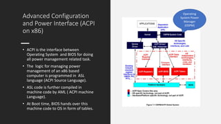
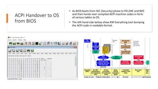
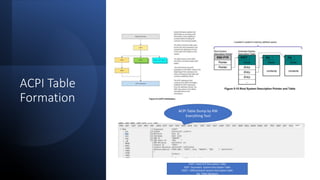
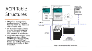
This presentation contains details about power management on x86 based PC from Intel corporation. The details here are taken from ACPI Specification on UEFI forum.
2. Advanced Configuration
and Power Interface (ACPI
on x86)
• ACPI is the interface between
Operating System and BIOS for doing
all power management related task.
• The logic for managing power
management of an x86 based
computer is programmed in ASL
language (ACPI Source Language).
• ASL code is further compiled in
machine code by AML ( ACPI machine
Language).
• At Boot time, BIOS hands over this
machine code to OS in form of tables.
Operating
System Power
Manager
(OSPM)
3. ACPI Handover to OS
from BIOS
• As BIOS boots from SEC (Security) phase to PEI,DXE and BDS
and then hands over compiled ACPI machine codes in form
of various tables to OS.
• The left-hand side below show RW Everything tool dumping
the ACPI code in readable format.
4. Global System
Power States
• A typical computer platform goes through
G0,G1, G2 and G3 states .
• Here G0 maps to S0 state (running system)
and G3 maps to shutdown.
• Further in G0 state, Various layers of
Power saving techniques are applied.
• These techniques eithers puts system in
sleep states like S0/S1/S2/S3 or S0ix (Run
time) state where all peripherals goes to
D0/D1/D2/D3 states.
• Beside various S0ix/Sx states, CPU cores
are further put into different C states
(C0/C1…C10) or P State (performance).
5. Device States for
Peripherals
• Device States for peripherals like any
PCI goes through D0 to D1/D2/D3hot
or D3cold.
• Most devices today doesn’t support
D1 and D2 states.
• D3cold provides more power saving
at the cost of increased latency while
waking up the system from sleep.
• D3hot provides less power saving
but better latency.
• D3cold can only be achieved by first
going in D3hot .
7. ACPI Table
Formation
ACPI Table Dump by RW
Everything Tool
FADT- Fixed ACP Description Table
SSDT- Secondary System Description Table
DSDT – Differentiated System Description table
Sig- Table Signature
8. ACPI Table
Structures
• PM (Power management)
Blocks in Memory contains
fields to inform the Hardware
to go to sleep state.
• GP (General Purpose) blocks
contains fields to mark any
event notification by GPIO
pins allocated to peripherals.
• Once PM/GP blocks gets some
valid events , they trigger
OSPM to execute specific ASL
methods from DSDT/SSDT
tables like putting the system
in sleep/hibernation or wake
the system.