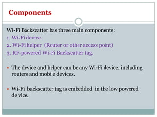
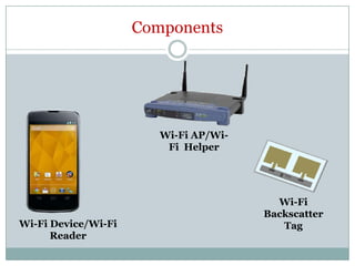
Wi-Fi BackscatterWi-Fi Backscatter
By Shivangi Gupta
Outline
 Introduction
 Background
 Components
 Working Working
 Conclusion
 References
Introduction
 Wi-Fi Backscatter is used for connecting “battery
free or RF powered device” with the Internet.
 For ex-
1. Sensors could be embedded ,to help monitor and1. Sensors could be embedded ,to help monitor and
track everything for the safety of bridges .
2. Health monitoring and communication updates
on our smart watches.
Background
Ambient-Backscatttering
- Enables two low powered devices to communicate
using “ambient(surrounding) RF signals” as the only
source of power.source of power.
- As it only uses existing signals, it does not require
any new infrastructure.
How does it works?
 Suppose there are 2 battery less devices with
interaction capabilities(antenna). They want to
communicate
 Alice wants to send some packet to Bob.
 Alice has a antenna ,which creates electrical energy
from radio signals(RF signals) .
 It uses this energy to backscatter towards Bob . While
backscattering, it uses Switch that sets the state ofbackscattering, it uses Switch that sets the state of
device .
Reflective-1
Absorbed -0
• Bob will receive the signal and decodes it.
Example
• Suppose a person left his keys on the couch
 Couch is being attached with small ambient
backscatter tag.
 Such tags are embedded with sensing capabilities.
 As soon as we left the couch , it will send a message
to our mobile that “ You lost your keys” using
ambient RF signals.
Example
Ambient
backscattering
Components
Wi-Fi Backscatter has three main components:
1. Wi-Fi device .
2. Wi-Fi helper (Router or other access point)
3. RF-powered Wi-Fi Backscatter tag.
 The device and helper can be any Wi-Fi device, including
routers and mobile devices.
 Wi-Fi backscatter tag is embedded in the low powered
de vice.
Components
Wi-Fi AP/Wi-
Wi-Fi Device/Wi-Fi
Reader
Wi-Fi AP/Wi-
Fi Helper
Wi-Fi
Backscatter
Tag
Wi-Fi Backscatter tag
 Wi-Fi Backscatter follows a request-response model.
 Wi-Fi Backscatter’s communication has two main
components:
-An uplink from the Wi-Fi Backscatter tag to the-An uplink from the Wi-Fi Backscatter tag to the
Wi-Fi device.
- A downlink from the Wi-Fi device to the Wi-Fi
Backscatter tag.
Uplink
• Wi-Fi Backscatter tag communicates with a Wi-Fi device
by modulating its Wi-Fi channel.
• Specifically, it conveys a ‘1’ and a ‘0’ bit by either
reflecting or absorbing the Wi-Fi packets received by thereflecting or absorbing the Wi-Fi packets received by the
mobile device.
• The reflected signals changes the per-packet CSI and
RSSI measurements, which the mobile device uses to
decode messages from the Wi-Fi Backscatter tag.
UPLINK
1.Modulating the Wi-Fi signals
 The Wi-Fi Backscatter tag conveys information by modulating the Wi-
Fi channel.
 To do this, it uses a “low power switch” that allows the antenna
impedance to be modulated by a transmitted bitimpedance to be modulated by a transmitted bit
stream.
 When we do modulation then CSI(Channel state information) and
RSSI(Received signal strength indicator) changes.
 “The antenna’s impedance affects the amount of signal
that is reflected by the tag.”
 By modulating this impedance, the tag can convey ‘1’ and ‘0’ bits.
Antenna
 Wi-Fi backscatter uses a special antenna which has
both impedance modulation as well as Wi-Fi
energy harvesting capability.
CSI/RSSI Modulation
Backscatter tag
2. Decoding at Wi-Fi reader
Decoding is done in 3 steps
 Signal Conditioning. Signal Conditioning.
 Exploiting Wi-Fi Frequency/Spatial Diversity
 Decoding bits from the Wi-Fi Backscatter tag.
Signal conditioning-
The goal of this step is two-fold:
1) Remove the natural temporal variations in the
channel measurements due to noise & mobility in the
environment.
2) normalize the channel measurements by mapping
to -1 and +1 values.
o -1
1 +1
Exploiting Wi-Fi Frequency Diversity
 Wi-Fi transmission span a bandwidth of 20MHz.At such a
wide bandwidth, signal experience “selective frequency
fading”.
 Now in order to get best reflected signal following steps are Now in order to get best reflected signal following steps are
followed
 1. Identify the good Wi-Fi subchannel and antennas-
To do this Wi-Fi reader uses correlation method. Everytime
, the backscatter tag adds one preamble at the message
beginning. When a transmission arrives ,the Wi-Fi reader
sorts sub-channel based on correlation value, then it will
select TOP TEN channels.
2. Combining information across the good Wi-Fi sub channels
 Sub-channel with low noise variance are given higher
weight.
 Sub-channel with higher noise are given lower weights.
CSIweighted = ∑ CSIi / (Ω i) 2CSIweighted = ∑ CSIi / (Ω i)
CSIi- It is the normalized CSI computed on the ith good Wi-Fi sub-
channel.
(Ωi )2 = the noise variance in the ith sub-channel.
CSI - is the Channel state information which tells about
scattering , fading , power decay effect over signal.
3.Decoding bits from Wi-Fi backscatter
 If the CSI weighted computed is greater
then 1,then the bit is interpreted as 1.
 Otherwise interpreted as 0. Otherwise interpreted as 0.
Downlink
 It is from Wi-Fi device to Backscatter tag.
 The challenges are
-Wi-Fi device can only send Wi-Fi packets.
-Wi-Fi backscatter cannot decode Wi-Fi
transmissions.
• The mobile device sends a pattern of short Wi-Fi packets — the
presence (absence) of the short Wi-Fi packet encodes the ‘1’ (‘0’) bit.
• The Wi-Fi Backscatter tag decodes this information by using our low-
power energy detector to differentiate between the presence and
absence of Wi-Fi packets.
Downlink
• For solving these challenges we have to follow 2
steps
1. Encoding at Wi-Fi reader.
2. Designing backscatter tag which can decode Wi-fi
transmissions.
1.Encoding at Wi-Fi device
 Encoding is done by sending or not sending the
packet.
 Let's say the device want to transmit 101000011, and
so on.
The Wi-Fi device will transmit The Wi-Fi device will transmit
packet 1
no packet/silence 0
packet 1
Problem
 Since we are encoding a “0” as silence, other Wi-Fi
devices around us will detect the medium as
unoccupied and can transmit in the silence spaces,
completely messing up our transmission.
 To prevent this we leverage a feature of the 802.11
protocol called CTS (clear to send), is used to
reserve the channel.
CTS-to-Self 0 0 0001 1 11
Wi-Fi
Wi-Fi
Device
Wi-Fi
Backscatter
Tag
•So before transmitting data, the Wi-Fi devices sends a
CTS-to-self packet to reserve the channel.
•Other Wi-Fi Devices will respect the 802.11 protocol and
abstain from transmitting in the silence periods.
2. Designing Backscatter tag
 Taking benefit from one of the feature of Wi-Fi
signal.
 Wi-Fi uses OFDM.
 OFDM uses multiple carrier wave to modulate one
signal.signal.
 OFDM has high Peak to Average power ratio, which
means the average energy in the Wi-Fi signal is
small, with occasional peaks spread out during the
transmission.
Example
You can see that the OFDM signal spends lots of its time
with very low amplitudes and occasionally has one of these
vary large peaks. This means that OFDM has a very high
peak-to-average power ratio, and we can use this to our
advantage.
Circuit of Backscatter tag
Envelope
Detector
Antenna
Peak finder Set threshold Comparator
Envelope Detector- It remove the carrier frequency of the Wi-Fi
transmissions.
Peak Finder Circuit- It finds the peaks in OFDM signals.
Set threshold- The capacitor computes a threshold using this peak value.
 Comparator- It takes 2 input , the threshold value and
the received signal
 It gives output as “1” bit, whenever the received signal
is greater than the threshold value and “0” bit otherwise.
 This whole packet detection circuit requires only few
µW of power.

Wi-fi backscatter

  • 1.
  • 2.
    Outline  Introduction  Background Components  Working Working  Conclusion  References
  • 3.
    Introduction  Wi-Fi Backscatteris used for connecting “battery free or RF powered device” with the Internet.  For ex- 1. Sensors could be embedded ,to help monitor and1. Sensors could be embedded ,to help monitor and track everything for the safety of bridges . 2. Health monitoring and communication updates on our smart watches.
  • 4.
    Background Ambient-Backscatttering - Enables twolow powered devices to communicate using “ambient(surrounding) RF signals” as the only source of power.source of power. - As it only uses existing signals, it does not require any new infrastructure.
  • 5.
    How does itworks?  Suppose there are 2 battery less devices with interaction capabilities(antenna). They want to communicate
  • 6.
     Alice wantsto send some packet to Bob.  Alice has a antenna ,which creates electrical energy from radio signals(RF signals) .  It uses this energy to backscatter towards Bob . While backscattering, it uses Switch that sets the state ofbackscattering, it uses Switch that sets the state of device . Reflective-1 Absorbed -0 • Bob will receive the signal and decodes it.
  • 7.
    Example • Suppose aperson left his keys on the couch  Couch is being attached with small ambient backscatter tag.  Such tags are embedded with sensing capabilities.  As soon as we left the couch , it will send a message to our mobile that “ You lost your keys” using ambient RF signals.
  • 8.
  • 9.
    Components Wi-Fi Backscatter hasthree main components: 1. Wi-Fi device . 2. Wi-Fi helper (Router or other access point) 3. RF-powered Wi-Fi Backscatter tag.  The device and helper can be any Wi-Fi device, including routers and mobile devices.  Wi-Fi backscatter tag is embedded in the low powered de vice.
  • 10.
    Components Wi-Fi AP/Wi- Wi-Fi Device/Wi-Fi Reader Wi-FiAP/Wi- Fi Helper Wi-Fi Backscatter Tag
  • 11.
    Wi-Fi Backscatter tag Wi-Fi Backscatter follows a request-response model.  Wi-Fi Backscatter’s communication has two main components: -An uplink from the Wi-Fi Backscatter tag to the-An uplink from the Wi-Fi Backscatter tag to the Wi-Fi device. - A downlink from the Wi-Fi device to the Wi-Fi Backscatter tag.
  • 12.
    Uplink • Wi-Fi Backscattertag communicates with a Wi-Fi device by modulating its Wi-Fi channel. • Specifically, it conveys a ‘1’ and a ‘0’ bit by either reflecting or absorbing the Wi-Fi packets received by thereflecting or absorbing the Wi-Fi packets received by the mobile device. • The reflected signals changes the per-packet CSI and RSSI measurements, which the mobile device uses to decode messages from the Wi-Fi Backscatter tag.
  • 13.
    UPLINK 1.Modulating the Wi-Fisignals  The Wi-Fi Backscatter tag conveys information by modulating the Wi- Fi channel.  To do this, it uses a “low power switch” that allows the antenna impedance to be modulated by a transmitted bitimpedance to be modulated by a transmitted bit stream.  When we do modulation then CSI(Channel state information) and RSSI(Received signal strength indicator) changes.  “The antenna’s impedance affects the amount of signal that is reflected by the tag.”  By modulating this impedance, the tag can convey ‘1’ and ‘0’ bits.
  • 14.
    Antenna  Wi-Fi backscatteruses a special antenna which has both impedance modulation as well as Wi-Fi energy harvesting capability. CSI/RSSI Modulation Backscatter tag
  • 15.
    2. Decoding atWi-Fi reader Decoding is done in 3 steps  Signal Conditioning. Signal Conditioning.  Exploiting Wi-Fi Frequency/Spatial Diversity  Decoding bits from the Wi-Fi Backscatter tag.
  • 16.
    Signal conditioning- The goalof this step is two-fold: 1) Remove the natural temporal variations in the channel measurements due to noise & mobility in the environment. 2) normalize the channel measurements by mapping to -1 and +1 values. o -1 1 +1
  • 17.
    Exploiting Wi-Fi FrequencyDiversity  Wi-Fi transmission span a bandwidth of 20MHz.At such a wide bandwidth, signal experience “selective frequency fading”.  Now in order to get best reflected signal following steps are Now in order to get best reflected signal following steps are followed  1. Identify the good Wi-Fi subchannel and antennas- To do this Wi-Fi reader uses correlation method. Everytime , the backscatter tag adds one preamble at the message beginning. When a transmission arrives ,the Wi-Fi reader sorts sub-channel based on correlation value, then it will select TOP TEN channels.
  • 18.
    2. Combining informationacross the good Wi-Fi sub channels  Sub-channel with low noise variance are given higher weight.  Sub-channel with higher noise are given lower weights. CSIweighted = ∑ CSIi / (Ω i) 2CSIweighted = ∑ CSIi / (Ω i) CSIi- It is the normalized CSI computed on the ith good Wi-Fi sub- channel. (Ωi )2 = the noise variance in the ith sub-channel. CSI - is the Channel state information which tells about scattering , fading , power decay effect over signal.
  • 19.
    3.Decoding bits fromWi-Fi backscatter  If the CSI weighted computed is greater then 1,then the bit is interpreted as 1.  Otherwise interpreted as 0. Otherwise interpreted as 0.
  • 20.
    Downlink  It isfrom Wi-Fi device to Backscatter tag.  The challenges are -Wi-Fi device can only send Wi-Fi packets. -Wi-Fi backscatter cannot decode Wi-Fi transmissions. • The mobile device sends a pattern of short Wi-Fi packets — the presence (absence) of the short Wi-Fi packet encodes the ‘1’ (‘0’) bit. • The Wi-Fi Backscatter tag decodes this information by using our low- power energy detector to differentiate between the presence and absence of Wi-Fi packets.
  • 21.
    Downlink • For solvingthese challenges we have to follow 2 steps 1. Encoding at Wi-Fi reader. 2. Designing backscatter tag which can decode Wi-fi transmissions.
  • 22.
    1.Encoding at Wi-Fidevice  Encoding is done by sending or not sending the packet.  Let's say the device want to transmit 101000011, and so on. The Wi-Fi device will transmit The Wi-Fi device will transmit packet 1 no packet/silence 0 packet 1
  • 23.
    Problem  Since weare encoding a “0” as silence, other Wi-Fi devices around us will detect the medium as unoccupied and can transmit in the silence spaces, completely messing up our transmission.  To prevent this we leverage a feature of the 802.11 protocol called CTS (clear to send), is used to reserve the channel.
  • 24.
    CTS-to-Self 0 00001 1 11 Wi-Fi Wi-Fi Device Wi-Fi Backscatter Tag •So before transmitting data, the Wi-Fi devices sends a CTS-to-self packet to reserve the channel. •Other Wi-Fi Devices will respect the 802.11 protocol and abstain from transmitting in the silence periods.
  • 25.
    2. Designing Backscattertag  Taking benefit from one of the feature of Wi-Fi signal.  Wi-Fi uses OFDM.  OFDM uses multiple carrier wave to modulate one signal.signal.  OFDM has high Peak to Average power ratio, which means the average energy in the Wi-Fi signal is small, with occasional peaks spread out during the transmission.
  • 26.
    Example You can seethat the OFDM signal spends lots of its time with very low amplitudes and occasionally has one of these vary large peaks. This means that OFDM has a very high peak-to-average power ratio, and we can use this to our advantage.
  • 27.
    Circuit of Backscattertag Envelope Detector Antenna Peak finder Set threshold Comparator Envelope Detector- It remove the carrier frequency of the Wi-Fi transmissions. Peak Finder Circuit- It finds the peaks in OFDM signals. Set threshold- The capacitor computes a threshold using this peak value.
  • 28.
     Comparator- Ittakes 2 input , the threshold value and the received signal  It gives output as “1” bit, whenever the received signal is greater than the threshold value and “0” bit otherwise.  This whole packet detection circuit requires only few µW of power.