Why do you need Inertial Navigation Systems for Missile Guidance.docx
1.
Why do youneed Inertial Navigation Systems for Missile
Guidance?
In missile guidance systems, Inertial Navigation Systems (INS) play a role by
providing self contained navigation capabilities. Here are several reasons why
Inertial Navigation Systems are crucial, for the direction and control of missiles;
Independent Operation - INS operates autonomously without relying on signals
or guidance. This independence is particularly important for missiles that operate
in environments where GPS signals may be disrupted or unavailable.
Continuous Guidance - INS ensures guidance throughout the missile's flight
allowing it to maintain position and velocity information even when external
guidance sources are not accessible.
Accuracy - Inertial Navigation Systems offer accuracy in determining a missile's
position, velocity and orientation. This level of precision is critical for precision
guided missiles that aim at targets.
Resistance to Electronic Countermeasures - Since INS operates independently of
signals it is less vulnerable to countermeasures intended to disrupt or jam
navigation systems. This enhances the resilience of missiles equipped with INS in
warfare scenarios.
Global Coverage - Inertial Navigation Systems provide coverage globally making
them suitable for long range missiles that need to traverse distances and operate
across different geographical regions – even in areas where GPS signals may be
weak or unreliable.
Launching Missiles from Different Platforms - Inertial Navigation Systems (INS)
allow missiles to be launched from a variety of platforms, such, as ground based
launchers, aircraft, ships or submarines. This flexibility in launch options is essential
for adapting missiles to scenarios.
2.
Quick Changesin Direction - By utilizing navigation systems, missiles can swiftly
change direction and perform maneuvers. This agility is crucial for evading threats
or homing in on moving targets.
Enhanced. Redundancy - INS is commonly used alongside guidance systems to
provide redundancy and enhance the reliability of the missile system. This
redundancy ensures that the missile maintains guidance even if certain
components fail or there are attempts at jamming.
Real Time Control - With navigation systems missiles can be controlled in time to
adjust their trajectory. This capability allows for course corrections and precise
targeting of the intended destination.
Extended Range Capabilities - Inertial Navigation Systems significantly contribute
to extending the range capabilities of missiles by providing accurate guidance over
distances. This feature is particularly important for missiles and those designed for
long range engagements.
Inertial Navigation Systems (INS) play a role in guiding missiles by offering
precise navigation capabilities necessary for successful guided missile missions.
Their solution offers a way to overcome the difficulties related to
countermeasures and ensures accurate targeting, in different operational
situations.
Missile Guidance System
To date there have been a total of 4 variations in the Missile Guidance System that
has been used for the Minuteman missile.
Starting with the Minuteman I, the NS-10Q Missile Guidance System was installed
with each missile, which relied upon the Autonetics D-17B computer as a part of its
guidance system.
The Minuteman II missile was upgraded with the NS-17 Missile Guidance System,
which incorporated the Autonetics D-37C computer.
In introducing the Minuteman III missile, which had the capacity of 3 Multiple
Independently Targetable Reentry vehicles, (MIRV) the new NS-20 Missile Guidance
3.
System was deployed,and relied on the Autonetics D-37D computer for its
processing power
December 4, 2007 marked the date of the final installation of the NS-50 Missile
Guidance System, MGS, at Malmstrom AFB in Great Falls, Montana. This final MGS
installation saw to completion all three missile wings being upgraded to the new NS-
50 guidance system. Boeing had previously purchased the Autonetics company, and
Boeing was responsible for the production of this latest missile guidance system.
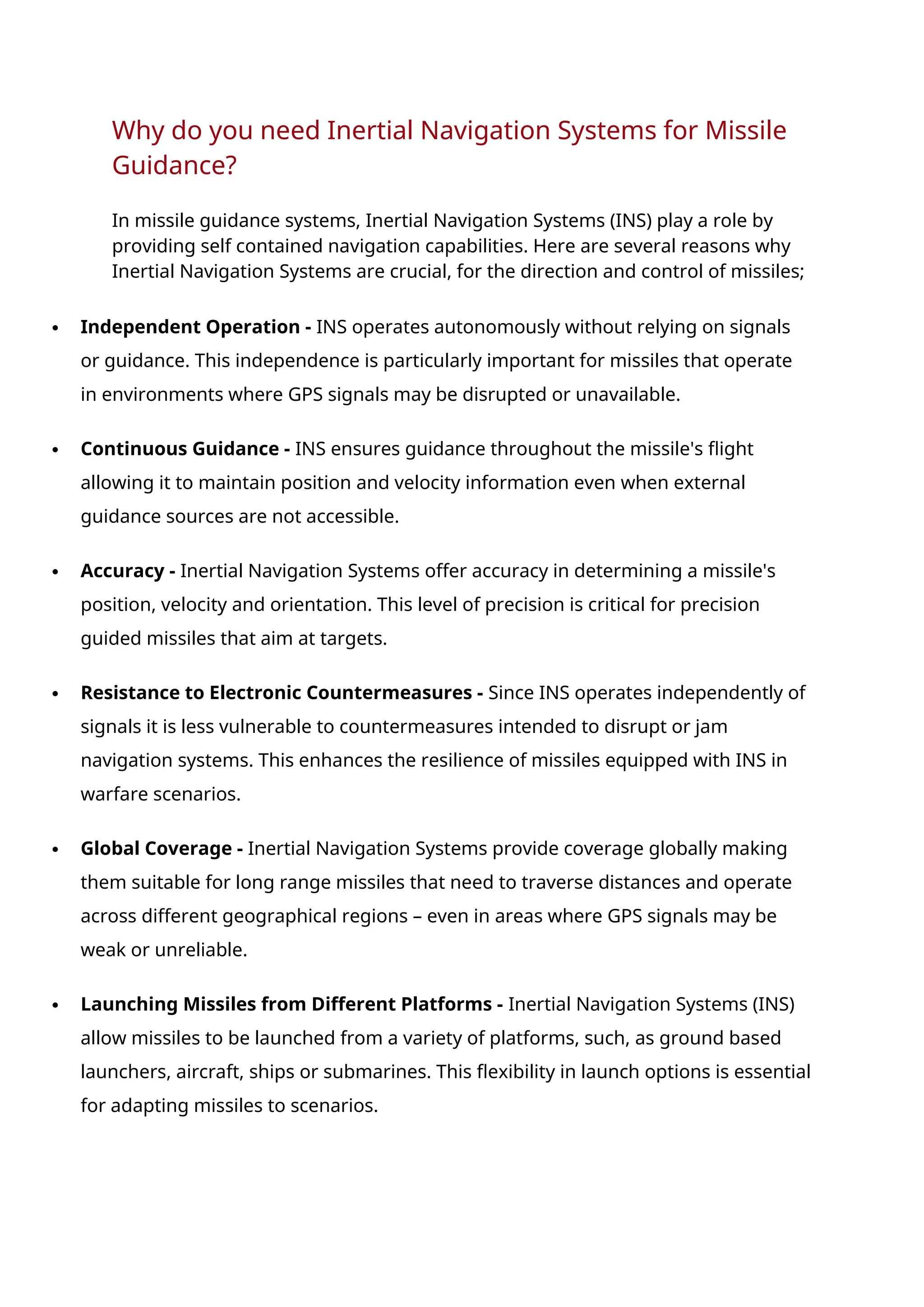
Autonetics D-17B Guidance Computer
Click on the image for a larger view
Autonetics D-17B Missile Guidance System Computer
For the Minuteman I missile, the complete Missile Guidance System consisted of a
D-17B computer, power supplies and a stable platform. The D-17B computer housed
6282 diodes, 1521 transistors, 1116 capacitors and 504 resistors. Fully assembled
the guidance system weighed approximately 62 pounds.
Each of these individual components were mounted on double copper clad, gold
plated, glass fiber laminate circuit boards. A total of 75 of these circuit boards make
up the D-17B computer, and each was coated with a flexible polyurethane
compound designed for protection from moisture and vibration. This weapon system
had an extreme demand for reliability and ruggedness.
In the image above, in the lower right quadrant, is the disk memory that housed a
6000 rpm magnetic disk used with the D-17B. It had a capacity of storing 5454
words. For the individual who is moderately to advanced in computer literacy,
Wikipedia discusses the D-17B and its components in much greater detail.
4.
Autonetics was theassociate contractor for the Minuteman guidance system, which
included both the prelaunch and flight software.
The targeting information that was uploaded in to the D-17B, used special
mylar/paper tape loaded with the targeting information on the tape. The targeting
coordinates was performed at Strategic Air Command Headquarters by the
Operational Targeting Program that was developed by TRW to execute on an IBM
709 mainframe computer.
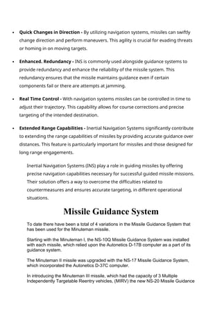
Autonetics D-37C Missile Guidance System Computer
Autonetics D-37C Guidance Computer
Once the Minuteman II missile entered into production, its Missile Guidance System
consisted of the Autonetics D-37C computer. The Minuteman II missile relied on the
NS-17 Missile Guidance Set to navigate its warhead to its target. This system was
designed around an all-inertial system that could store multiple preprogrammed
targets in its internal memory.
Inertial guidance systems do not rely on observations of positions of the stars or land
positions, nor does it rely on radio or radar signals. Essentially this system does not
rely on any information from outside the missile. The inertial navigator that is
designed into the NS-17 Missile Guidance Set provides the guidance information
using gyroscopes that indicate direction, as well as accelerometers that measure
changes in the speed and direction of the missile.
5.
The D-37C computerthen compiles this information to calculate the missiles' current
position and makes adjustments in guiding the missile on its course. Given that all of
the information needed to "steer" the missile to its intended target was based on
components built into the missile, enemies would not be able to introduce to the
guidance system false or confusing information.
This Autonetics computer consisted of four main sections. The memory, the central
processing unit (CPU), and the input and output units. The memory contained a two
sided fixed head magnetic disk which rotates at 6000 rpm. Its storage capacity could
contain up to 7222 words.
The NS-17 Missile Guidance Set and D-37C computer had an added design that
implemented a "code inserter verifier" that was used at the Wing headquarters to
generate the targeting codes that would be uploaded to the D-37C computer. The Air
Force required not only that the flight program software was correct, but that there
was no additional code that could lead to an unauthorized or accidental launch.
As was used with the D-17B computer, TRW continued its role in compiling the
targeting information for the Minuteman missile, which was first referred to as
independent verification and validation, and would later be designated as Nuclear
Safety Cross Check Analysis, (NRSCCA). Logicon RDA was then selected to
perform the NSCCA of the targeting and execution plan software programs
developed by TRW.
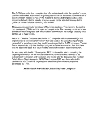
Autonetics D-37D Missile Guidance System Computer
6.
Autonetics D-37D GuidanceComputer
Click on the image for a larger view
The NS-20 was the name of the first Minuteman III Missile Guidance System, MGS.
The purpose of the NS-20 MGS is to perform ground and in-flight functions for the
Minuteman III weapon system. This system consists of the Autonetics D-37D
7.
computer, a unitdesigned for inertial measurement, cabling, coolant hoses and other
hardware.
While in the Launch Facility, the Missile Guidance System continually communicates
to the ground system within the LF, and responds to commands received from the
ground system, and constantly monitors and reports on the health of the missile
system.
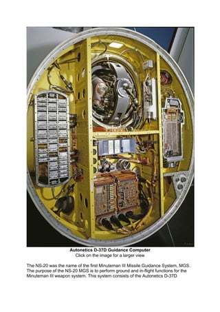
Autonetics D-37D Gyro
Click on the image for a larger view
The Minuteman missiles has three solid fuel rocket boosters, each designed for the
various stages of flight, from launch, mid flight and the third and final stage of flight,
before the payload bus, which contains the Missile Guidance System and Post Boost
Propulsion System, separates from the third booster. At the initiation of launch and
into the first stage of flight, the Missile Guidance System flight computer sends
commands to the nozzle control unit to keep the missile on the exact course required
for the reentry vehicles to reach their specific targets.
With each of the three stages of rocket boosters, the D-37D flight computer has the
ability to sense when the rocket booster is nearly depleted of fuel, at which point it
sends a command to separate that nearly spent booster, and ignite the next stage
booster. The inertial guidance system then sends signals to the flight computer,
which then sends commands to the Thrust Vector Control (TVC) Unit, on each of the
succeeding solid rocket boosters, insuring that the missile remains on course.
For further discussion and more detailed information on the Payload Bus, also
referred to as the Post Boost Propulsion System, follow the link below
8.
Payload Bus- Post Boost Propulsion System
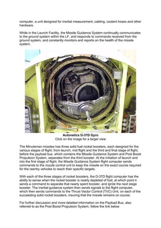
NS-50 Missile Guidance System - Malmstrom AFB
Click on the image for a larger view
The NS-50 Missile Guidance System (sometimes referred to as the Missile Guidance
Set) is the result of the Minuteman III Guidance Replacement Program, GRP, which
came about after a five year engineering and manufacturing development program
(EMD). The Air Force established this program in order to extend the service life of
the Missile Guidance System beyond the year 2020.
Back in 1996 a number of critical design reviews were established, to identify design
weaknesses in the MGS - the NS-20 Missile Guidance Set/System. As a result, a
more robust, less vulnerable system was created, allowing for a consistently more
accurate Missile Guidance System, that also requires less maintenance over time.
Less maintenance means less operational cost.
In September 1998 the Guidance Replacement Program was able to successfully
perform a second flight test of the GRP from Vandenberg, AFB in California. After a
9.
total of sevenflight tests, the Air Force determined that the accuracy results were not
within specifications. They were able to determine that this was being caused by two
primary sources of errors in the guidance system software.
Moving forward, full capacity of production of the NS-50 MGS started in early 2000.
Boeing was awarded the contract for production, which oversaw a total of 652
Missile Guidance Systems being built to support the 500 operational Minuteman III
missiles that were deployed at the time. The final MGS was installed December 4,
2007, on a Minuteman III missile at Malmstrom Air Force Base in Great Falls,
Montana.
The image below provides a comparison between the older NS-20 Missile Guidance
Set in relation to the latest NS-50 MGS. The NS-50 design is functionally similar to
the NS-20.
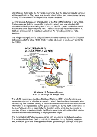
Minuteman III Guidance System
Click on the image for a larger view
The NS-50 incorporates the Gyro Stabilized Platform, GSP, which functions as a
means to measure the missile's acceleration, which then translates the acceleration
into velocity. The missile's velocity is then combined with attitude information and this
information is then processed by the guidance computer during flight. In reference to
the term "attitude", this is essentially the direction and/or angle that the missile is
heading. Without a precise attitude, the Minuteman missile will not be able to deliver
its warhead/warheads accurately to its programmed target.
The Gyro Stabilized Platform was designed with an external gimbal configuration.
The platform is stabilized (both prior to flight, as well as during flight) by two dual-
axis, free rotor gyros that are supported on self generated gas bearings. One gyro
10.
functions as thepitch and roll axis stabilization reference. The second gyro functions
as determining the azimuth stabilization reference.
A dual-axis gas bearing gyro was chosen due to it dynamic stability over extended
periods of operation, as well as its ability to withstand high G loads, without
impacting its ability to function with precision. The Guidance and Control system is
designed as such, that the gyro rotors can self generate the gas necessary to
provide a cushion in the gas insulated bearings. Given the high G forces impacting
the missile as a whole upon launch, having bearings protected by a gas, provides
not only the ability to perform its task with precision, but provides a significant
reduction in the wear and tear on the gyros and their bearings.
The Gyro Stabilized Platform also integrates three Pendulous Integrating Gyroscopic
Accelerometers, PIGAs, to measure the missile's acceleration along each of its three
axes. Each of the three accelerometers have a gyroscopic pendulous mass
contained in the device, which houses a gyroscopic pendulous mass which is
floating in a liquid to minimize friction and bearing load. Sensors within the
accelerometers measure the acceleration of the missile, based on the position of the
pendulous mass, which then provides output information to the guidance and control
computer based on measurements of the acceleration of the Minuteman missile.
The video below is a CGI depiction of a launch of a Minuteman III missile. The video
shows how each stage of the 3 stages of the solid rocket boosters operate,
culminating with the final release of Post Boost Propulsion System (payload bus)
which then maneuvers the reentry vehicle to the desired point of release. The video
is a helpful visual reference of how the Missile Guidance System described above,
performs what it was designed to do, from launch to the release of the reentry
vehicle.
This video was produced by Northrop Grumman, a major company that has been an
integral partner with the Air Force for many years. Northrop Grumman has been
supplying major components for the Minuteman missile weapons system for quite
some time.
The video format is an mp4, which will require that your computer have the ability to
play mp4 files. Windows Media Player version 12 will allow you to view this video.
For those who aren't set up to play an mp4 video, one option suggested is using the
Media Player Classic video player, a free program that works quite well. https://mpc-
hc.org/
CGI Video - Minuteman III Missile Launch
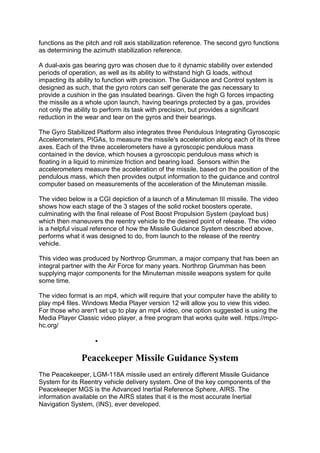
Peacekeeper Missile Guidance System
The Peacekeeper, LGM-118A missile used an entirely different Missile Guidance
System for its Reentry vehicle delivery system. One of the key components of the
Peacekeeper MGS is the Advanced Inertial Reference Sphere, AIRS. The
information available on the AIRS states that it is the most accurate Inertial
Navigation System, (INS), ever developed.
11.
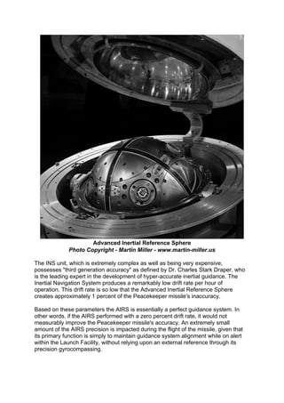
Advanced Inertial ReferenceSphere
Photo Copyright - Martin Miller - www.martin-miller.us
The INS unit, which is extremely complex as well as being very expensive,
possesses "third generation accuracy" as defined by Dr. Charles Stark Draper, who
is the leading expert in the development of hyper-accurate inertial guidance. The
Inertial Navigation System produces a remarkably low drift rate per hour of
operation. This drift rate is so low that the Advanced Inertial Reference Sphere
creates approximately 1 percent of the Peacekeeper missile's inaccuracy.
Based on these parameters the AIRS is essentially a perfect guidance system. In
other words, if the AIRS performed with a zero percent drift rate, it would not
measurably improve the Peacekeeper missile's accuracy. An extremely small
amount of the AIRS precision is impacted during the flight of the missile, given that
its primary function is simply to maintain guidance system alignment while on alert
within the Launch Facility, without relying upon an external reference through its
precision gyrocompassing.