This document discusses various methods of assessing difficulty for removal of impacted mandibular third molars based on panoramic radiographs. It describes several classification systems:
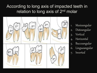
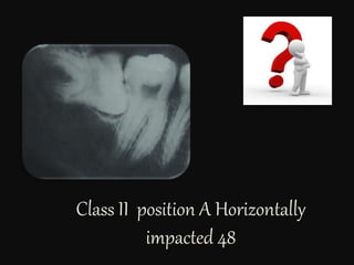
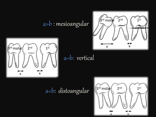
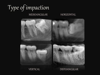
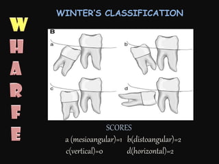
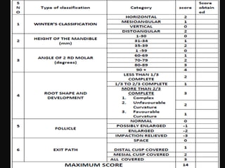
- Winter's classification which evaluates angulation.
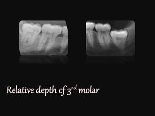
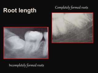
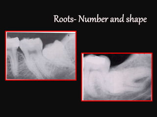
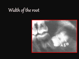
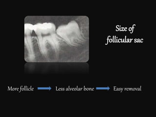
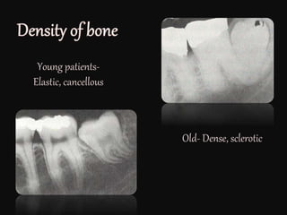
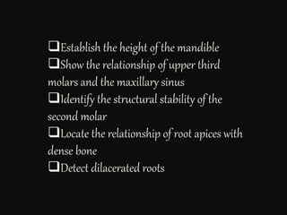
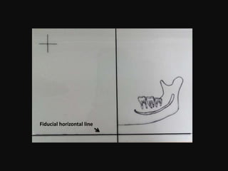
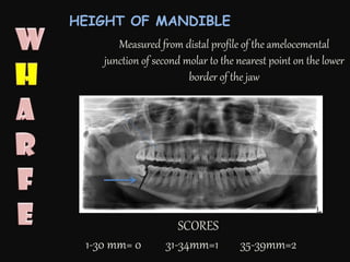
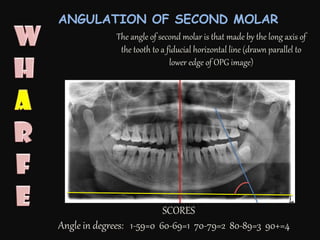
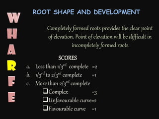
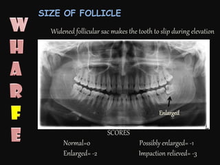
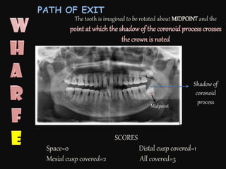
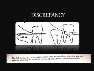
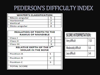
- Assessment of height of the mandible, angulation of the second molar, root shape and development, follicle size, and path of tooth exit. Scores are assigned in each category.
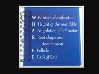
- WHARFE assessment combines the features assessed above into a single score to determine overall difficulty.
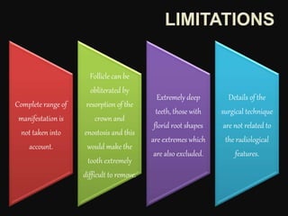
However, the document notes that radiographs only provide limited information and may not capture the full range of variations encountered. The actual difficulty during surgery may differ from radiographic assessments. Surgeons should not


![IMPACTED_TEETH[1] FDFG - Read-Only.pptx](https://cdn.slidesharecdn.com/ss_thumbnails/impactedteeth1-read-only-250217012502-47d43e91-thumbnail.jpg?width=640&height=640&fit=bounds)


