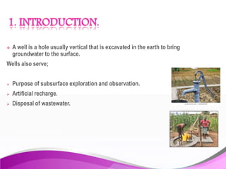
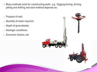
GROUND HYDROLOGY
1. INTRODUCTION
2.WELL COMPLETION
3.CONCLUSION
4.REFERENCE
 A well is a hole usually vertical that is excavated in the earth to bring
groundwater to the surface.
Wells also serve;
 Purpose of subsurface exploration and observation.
 Artificial recharge.
 Disposal of wastewater.
1. Shallow wells.
2. Deep wells.
 Shallow wells are dug,bored,driven or jetted while,
 Deep wells are drilled by cable tool or Rotary methods.
12m deep well dug by women in Kerala.
Shallow well dug in Kenya. East
Africa
 Many methods exist for constructing wells e.g. Digging boring, driving,
jetting and drilling and each method depends on;
 Purpose of well.
 Quantity of water required.
 Depth of groundwater.
 Geologic conditions.
 Economic factors..etc
 After a well has been drilled ,it should be completed ,developed and
maintained for optimum yield .
Well completion involves;
a) Placement of casing.
b) Cementing.
c) Placement of well screen.
d) Gravel packing.
However wells in hard rock formations can be left as open holes
Here a casing pipe is lowered into the dug or drilled well serving as a lining.
Types of casing
 Surface casing
 Pump chamber casing
Purpose of casing
 to maintain an open hole from the ground surface to the aquifer.
 Seals out surface water and any undesirable groundwater .
 Provides structural support against caving materials outside the well.
Surface casing
It's installed from the ground surface through upper strata
Of unstable or fractured materials into a stable and if possible relatively
Impermeable material.
Purpose;
 Supporting unstable materials during drilling.
 Reducing loss of drilling fluids.
 Facilitating installation or removal of other casing.
 Aiding in placing a sanitary seal.
 Serving as a reservoir for a gravel pack.
Surface casing may be temporary during drilling or permanent.
The following materials are commonly employed for well casings;
 Wrought iron.
 Unalloyed steel.
 Ing of iron.
However where corrosion and incrustation is a problem, non metallic pipes are
employed such as ;
 ceramic clay.
 Concrete
 Asbestos-cement
 Plastic.
 Fiberglass-reinforced plastic pipe.
However this materials have less strength in comparison to steel.
10
STEEL PVC
ASBESTOS
CEMENT
CONCRETE
Fiber reinforced plastic
pipes
 In cable tool drilling ,the casing is driven into the place .
 In rotary methods ,the casing is smaller than the drilled hole and hence can
be lowered into place.
NOTE
PVC (poly vinyl chloride) is widely employed as casing for shallow
and small observation wells.
Wells are cemented;
 in the annular space surrounding the casing to Prevent entrance of water
of unsatisfactory quality.
 To prevent the casing against exterior corrosion.
 To allow a maximum amount of water to enter the well with a minimum of
hydraulic resistance.
 Cement grout consisting of a mixture of cement and water ,sometimes
various additives can be placed by a dump bailer , tremie pipe or by
pumping.
 The grout should be introduced at the bottom of the space to be grouted
to ensure that the zone is properly sealed.
 In consolidated formations ( e.g. hard rocks) ,the material surrounding
the well is stable and hence groundwater can enter directly into an
uncased well.
 Unconsolidated formations ( e.g. sand, silt etc) however wells are
equipped with screens.
Screens;
 Stabilize the sides of the hole.
 Prevent sand movement into the well.
 Allow a maximum amount of water to enter the well with a minimum of
hydraulic resistance.
1. Perforated casings
2. Manufactured or commercial screens
Perforated casings
In such casings the perforation is done by
 Special cutting knife
 Sawing
 Machining
 Torch- cutting slots
The slot openings range from 1-6mm and with the larger slot having the
maximum percentage of open area as 12%
Demerits
 Large irregular openings
 Small percentage of open area
 Difficulty in controlling entry of sand with water during dumping
Manufactured screens
Types of manufactured screens include:
 Punched
 Stamped
 Louvered
 Wire-wound perforated pipe
 Continuous-slot wire wound screens .
This is the most efficient type as it possesses the largest open area and
can be closely matched to aquifer conditions.
NOTE:
For practical purposes a minimum open area of 15% is desirable.
This value is however readily obtained with commercial screens but not
with perforated casing.
Placement of a well screen greatly influence the areas contributing recharge
To well and vulnerability of the well to contamination
 Non ferrous metals ,alloy and plastics are often used to prolong well life
and efficient operation.
Examples;
 Plastics
 Concrete
 Asbestos-cement
 Wood
 Coated base metals
 In areas where corrosion may possibly occur, metals and their alloys are
used
There are various methods employed for installation of well screens among
which include;
I. Pull back method
II. Open hole method
III. bail down method
IV. Wash-down method.
 The casing is driven to full depth of the well.
 The screen is lowered inside the casing and allowed to rest at the
bottom.
 The casing pipe is then pulled up enough expose the full length of the
screen in the water bearing formation.
 Using the swedge block, the lead packer provided at the top of the well
screen is expanded to make a sand tight seal between the screen and
the inside of the casing.
APPLICATIONS.
 Cable-tool drilled wells.
 Rotary drilled wells.
In this method,
 Casing is first sunk to a depth a little below the desired positions for the
top of well screen.
 An open hole is then drilled in the water bearing sand thus the casing
being filled with the mud fluid.
 The well screen is then lowered in position and the lead packer is
swedged.
APPLICATION.
 In Rotary drilled wells
Note:
Manufactured screens are preferred to perforated casings due
to;
 The ability to tailor opening sizes to aquifer conditions.
 The larger percentage of open area that can be achieved.
Note:
Selection of screen diameters should be made on basis of the ;
 Desired well yield
 Aquifer thickness
To minimize well loses and screen clogging ,entrance velocities
kept within specified limits.
The screen entrance velocity is defined by the expression;
Where ; is screen velocity
Q is discharge of well
c is clogging coefficient
is screen diameter
is screen length.
P is percentage of open area
A gravel pack is a sand-control method used to prevent production of
formation sand .
Usually a screen is placed in the wellbore and the surrounding annulus
packed with prepared gravel of a specific size designed to prevent the
passage of formation sand.
Functions:
 Stabilizes the aquifer.
 Minimizes sand pumping
 Permits use of large screen slot with a minimum open area
 Provides an annular zone of high permeability which increases the
effective radius and yield of well.
 The maximum grain size of a pack should be near 1cm while the
thickness should be in the range of 8-15cm
 Selected gravel should be washed and screened siliceous material that
is rounded ,abrasive-resistant and dense.
 Gravel should be placed in a manner as to ensure complete filling of the
annular space and to minimize segregation
 A common procedure is to extend two tremie pipes to the bottom of the
well on opposite sides of the screen
 Gravel is poured ,washed or pumped into the tremie pipes
 These are then withdrawn in stages as the pack is placed.
 In cable-tool holes the inner casing and screen are set inside the blank
outer casing the annular space is filled with gravel and there after the
outer casing is pulled out of the well.
 In sandy aquifers where the gravel pack is most essential deep wells
should be constructed by the rotary or reverse circulation rotary
method.
 The drilling fluid should be circulated and diluted with water before the
gravel is introduced.
From experiences , the failure of wells has been mostly due to
depletion of groundwater , incrustation ,corrosion, defects in
well construction such as poor casing ,improper screening
..etc hence a proper well completion will eventually adds
life to a well.
1. Groundwater hydrology
by David K.Todd and Larry W. Mays
2. Groundwater hydrology
H.M Rhagunath
3. Images from Wikipedia
THANK YOU

Well completion.

  • 1.
  • 2.
  • 3.
     A wellis a hole usually vertical that is excavated in the earth to bring groundwater to the surface. Wells also serve;  Purpose of subsurface exploration and observation.  Artificial recharge.  Disposal of wastewater.
  • 4.
    1. Shallow wells. 2.Deep wells.  Shallow wells are dug,bored,driven or jetted while,  Deep wells are drilled by cable tool or Rotary methods. 12m deep well dug by women in Kerala. Shallow well dug in Kenya. East Africa
  • 5.
     Many methodsexist for constructing wells e.g. Digging boring, driving, jetting and drilling and each method depends on;  Purpose of well.  Quantity of water required.  Depth of groundwater.  Geologic conditions.  Economic factors..etc
  • 6.
     After awell has been drilled ,it should be completed ,developed and maintained for optimum yield . Well completion involves; a) Placement of casing. b) Cementing. c) Placement of well screen. d) Gravel packing. However wells in hard rock formations can be left as open holes
  • 7.
    Here a casingpipe is lowered into the dug or drilled well serving as a lining. Types of casing  Surface casing  Pump chamber casing Purpose of casing  to maintain an open hole from the ground surface to the aquifer.  Seals out surface water and any undesirable groundwater .  Provides structural support against caving materials outside the well.
  • 8.
    Surface casing It's installedfrom the ground surface through upper strata Of unstable or fractured materials into a stable and if possible relatively Impermeable material. Purpose;  Supporting unstable materials during drilling.  Reducing loss of drilling fluids.  Facilitating installation or removal of other casing.  Aiding in placing a sanitary seal.  Serving as a reservoir for a gravel pack. Surface casing may be temporary during drilling or permanent.
  • 9.
    The following materialsare commonly employed for well casings;  Wrought iron.  Unalloyed steel.  Ing of iron. However where corrosion and incrustation is a problem, non metallic pipes are employed such as ;  ceramic clay.  Concrete  Asbestos-cement
  • 10.
     Plastic.  Fiberglass-reinforcedplastic pipe. However this materials have less strength in comparison to steel. 10 STEEL PVC ASBESTOS CEMENT CONCRETE Fiber reinforced plastic pipes
  • 11.
     In cabletool drilling ,the casing is driven into the place .  In rotary methods ,the casing is smaller than the drilled hole and hence can be lowered into place. NOTE PVC (poly vinyl chloride) is widely employed as casing for shallow and small observation wells.
  • 13.
    Wells are cemented; in the annular space surrounding the casing to Prevent entrance of water of unsatisfactory quality.  To prevent the casing against exterior corrosion.  To allow a maximum amount of water to enter the well with a minimum of hydraulic resistance.  Cement grout consisting of a mixture of cement and water ,sometimes various additives can be placed by a dump bailer , tremie pipe or by pumping.  The grout should be introduced at the bottom of the space to be grouted to ensure that the zone is properly sealed.
  • 15.
     In consolidatedformations ( e.g. hard rocks) ,the material surrounding the well is stable and hence groundwater can enter directly into an uncased well.  Unconsolidated formations ( e.g. sand, silt etc) however wells are equipped with screens. Screens;  Stabilize the sides of the hole.  Prevent sand movement into the well.  Allow a maximum amount of water to enter the well with a minimum of hydraulic resistance.
  • 16.
    1. Perforated casings 2.Manufactured or commercial screens Perforated casings In such casings the perforation is done by  Special cutting knife  Sawing  Machining  Torch- cutting slots
  • 17.
    The slot openingsrange from 1-6mm and with the larger slot having the maximum percentage of open area as 12% Demerits  Large irregular openings  Small percentage of open area  Difficulty in controlling entry of sand with water during dumping Manufactured screens Types of manufactured screens include:  Punched  Stamped  Louvered  Wire-wound perforated pipe
  • 18.
     Continuous-slot wirewound screens . This is the most efficient type as it possesses the largest open area and can be closely matched to aquifer conditions. NOTE: For practical purposes a minimum open area of 15% is desirable. This value is however readily obtained with commercial screens but not with perforated casing.
  • 19.
    Placement of awell screen greatly influence the areas contributing recharge To well and vulnerability of the well to contamination
  • 20.
     Non ferrousmetals ,alloy and plastics are often used to prolong well life and efficient operation. Examples;  Plastics  Concrete  Asbestos-cement  Wood  Coated base metals  In areas where corrosion may possibly occur, metals and their alloys are used
  • 22.
    There are variousmethods employed for installation of well screens among which include; I. Pull back method II. Open hole method III. bail down method IV. Wash-down method.
  • 23.
     The casingis driven to full depth of the well.  The screen is lowered inside the casing and allowed to rest at the bottom.  The casing pipe is then pulled up enough expose the full length of the screen in the water bearing formation.  Using the swedge block, the lead packer provided at the top of the well screen is expanded to make a sand tight seal between the screen and the inside of the casing. APPLICATIONS.  Cable-tool drilled wells.  Rotary drilled wells.
  • 24.
    In this method, Casing is first sunk to a depth a little below the desired positions for the top of well screen.  An open hole is then drilled in the water bearing sand thus the casing being filled with the mud fluid.  The well screen is then lowered in position and the lead packer is swedged. APPLICATION.  In Rotary drilled wells
  • 25.
    Note: Manufactured screens arepreferred to perforated casings due to;  The ability to tailor opening sizes to aquifer conditions.  The larger percentage of open area that can be achieved. Note: Selection of screen diameters should be made on basis of the ;  Desired well yield  Aquifer thickness To minimize well loses and screen clogging ,entrance velocities kept within specified limits.
  • 26.
    The screen entrancevelocity is defined by the expression; Where ; is screen velocity Q is discharge of well c is clogging coefficient is screen diameter is screen length. P is percentage of open area
  • 28.
    A gravel packis a sand-control method used to prevent production of formation sand . Usually a screen is placed in the wellbore and the surrounding annulus packed with prepared gravel of a specific size designed to prevent the passage of formation sand. Functions:  Stabilizes the aquifer.  Minimizes sand pumping  Permits use of large screen slot with a minimum open area  Provides an annular zone of high permeability which increases the effective radius and yield of well.
  • 29.
     The maximumgrain size of a pack should be near 1cm while the thickness should be in the range of 8-15cm  Selected gravel should be washed and screened siliceous material that is rounded ,abrasive-resistant and dense.  Gravel should be placed in a manner as to ensure complete filling of the annular space and to minimize segregation  A common procedure is to extend two tremie pipes to the bottom of the well on opposite sides of the screen  Gravel is poured ,washed or pumped into the tremie pipes  These are then withdrawn in stages as the pack is placed.
  • 30.
     In cable-toolholes the inner casing and screen are set inside the blank outer casing the annular space is filled with gravel and there after the outer casing is pulled out of the well.  In sandy aquifers where the gravel pack is most essential deep wells should be constructed by the rotary or reverse circulation rotary method.  The drilling fluid should be circulated and diluted with water before the gravel is introduced.
  • 32.
    From experiences ,the failure of wells has been mostly due to depletion of groundwater , incrustation ,corrosion, defects in well construction such as poor casing ,improper screening ..etc hence a proper well completion will eventually adds life to a well.
  • 33.
    1. Groundwater hydrology byDavid K.Todd and Larry W. Mays 2. Groundwater hydrology H.M Rhagunath 3. Images from Wikipedia
  • 34.