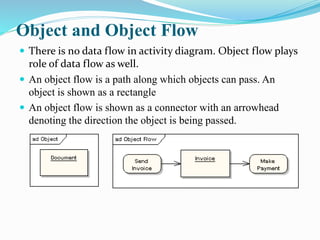
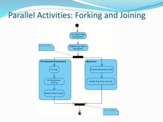
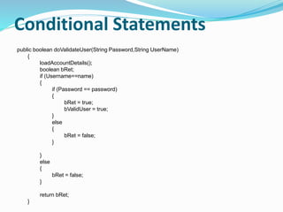
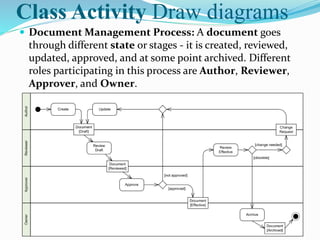
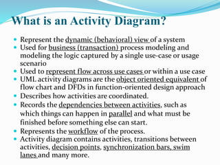
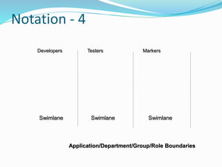
Here is an activity diagram for the document management process:
[DOCUMENT MANAGEMENT PROCESS]
Create Document -> Review Document -> [Approve?] -> Yes -> Archive Document | No -> Update Document -> Review Document
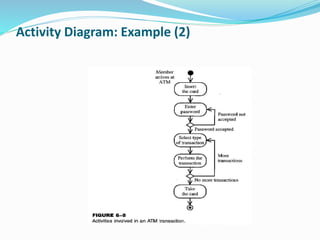
The activity starts with an author creating a document. The document is then sent to a reviewer for review. There is a decision point to determine if the document is approved. If approved, the document is archived. If not approved, the document goes back to the author for updates, and then back to the reviewer again for additional review.
Roles:
Author
Reviewer
Approver
Owner
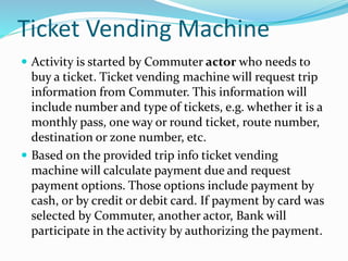
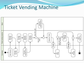
Here is an activity diagram for the ticket vending machine process:
[TICKET

![Notation - 2
Activity1
[x>0]
[x=0]
[x<0]
[x>0]
[x=0]
[x<0]
3. Decision Diamond](https://image.slidesharecdn.com/week07a-221101173341-5dabe063/85/week07a-pdf-4-320.jpg)
![Example: Business Level Activity Diagram of Library
member Librarian
[borrower]
[returner]
Find book on shelf
Wait in queue
Prepare for next
member
Record borrowing
Record return Put book back to shelf
[returning]
[borrowing]](https://image.slidesharecdn.com/week07a-221101173341-5dabe063/85/week07a-pdf-8-320.jpg)
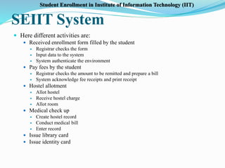
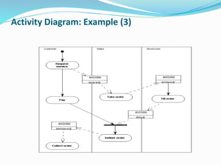
![Detailed Activity Diagram of SEIIT
Fill-in
form
Check
form
[Incorrect]
[Correct]
Display student
screen
Input student
information
Verify the
applications
Search for Student
selection list
[No]
Regret message
[Yes]
Regret
registration
[No Match]
[Match]
Create record 1](https://image.slidesharecdn.com/week07a-221101173341-5dabe063/85/week07a-pdf-28-320.jpg)
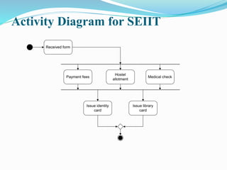
![Activity Diagram of SEIIT with Swim Lane
Fill-in
form
Check
form
[Incorrect]
[Correct]
Display student
screen
Input student
information Search for Student
selection list
Verify the
applications
Regret message
Create record
Regret
registration
[No Match]
[Match]
[No]
[Yes]
1
Student
Registrar
System](https://image.slidesharecdn.com/week07a-221101173341-5dabe063/85/week07a-pdf-30-320.jpg)