
Recommended
More Related Content
Similar to Fundamentals of Software Engineering
Similar to Fundamentals of Software Engineering (20)
More from Madhar Khan Pathan
More from Madhar Khan Pathan (20)
Recently uploaded
Recently uploaded (20)
Fundamentals of Software Engineering
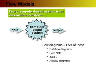
- 1. Every computer-based system is anEvery computer-based system is an information transform ....information transform .... computercomputer basedbased systemsystem inputinput outputoutput Flow Models Flow diagrams – Lots of these! Dataflow diagrams Petri Nets IDEF0 Activity diagrams
- 2. Flow Models: UML Activity Diagrams We have gone through great pains in use case modeling to say the use case diagram is not a flow diagram But we have flow right in front of us in the scenarios! So where do we capture it in our model? UML Activity Diagrams UML equivalent of a flowchart You can represent (multiple) flows directly with the Activity diagram
- 3. What Is an Activity Diagram? An activity diagram in the use-case model can be used to capture the activities and actions performed in a use case. It is essentially a flow chart, showing flow of control from one activity or action to another. Flow of Events This use case starts when the Registrar requests that the system close registration. 1. The system checks to see if registration is in progress. If it is, then a message is displayed to the Registrar and the use case terminates. The Close Registration processing cannot be performed if registration is in progress. 2. For each course offering, the system checks if a professor has signed up to teach the course offering and at least three students have registered. If so, the system commits the course offering for each schedule that contains it. Activity 1 Activity 3 Activity 2
- 4. Example: Activity Diagram Synchronization Bar (Fork) Guard Condition Synchronization Bar (Join) Decision Concurrent Threads Transition Select Course [ add course ] Check Schedule Check Pre-requisites Assign to Course Resolve Conflicts Update Schedule Delete Course [ checks completed ] [ checks failed ] [ delete course ] Activity/Action Final / Termination Merge Initial / Start
- 5. Activity Diagrams Summary of Notation: • Action/Activity state – Action states cannot be decomposed, Activity states may be (UML 1.5 - as of UML 2.0 replaced with Activity frames) • Transition – control flow; a transition is triggered upon completion of some activity • Decision/Merge point – standard if-else style logic; also supports iteration. Guard conditions indicated in brackets in each transition. • Object node – may be (typically not) included to show where an object’s state may change. • Synchronization bar – supports fork/join semantics for concurrent processing • Swimlanes – partition by responsibility, not thread Label [state] label
- 6. Activity Diagram Action A step in the flow of events Decision Flows split based on a guard condition Flow Show the sequence of activities Fork Beginning of concurrent flows Join End of concurrent flow Figure from IBM
- 7. Mapping Who does What to Whom Examples so far show us what actions happen But “WHO” does each action and “WHEN”? Swimlanes Partition activities according to who does them Who can be actors, system components, whatever When is indicated top-to-bottom (like a sequence diagram) or left-to-right To Whom? Activity diagrams can show relationships to objects that are affected by actions
- 8. Example by Bau Yoon Teck
- 9. Activity Diagram Summary Pros: Map use case scenarios directly on to actions Most intuitive for most procedural programmers Includes constructs concurrency and task assignment Includes constructs for top down decomposition (activity frames) Cons: Some confusion of the relationship between activity diagrams and statecharts Some changes in terminology from 1.5 to 2.0 Relatively poor tool support Recommendation: Useful early in analysis, after use cases but before interaction diagrams
- 10. Activity Diagram Summary Pros: Map use case scenarios directly on to actions Most intuitive for most procedural programmers Includes constructs concurrency and task assignment Includes constructs for top down decomposition (activity frames) Cons: Some confusion of the relationship between activity diagrams and statecharts Some changes in terminology from 1.5 to 2.0 Relatively poor tool support Recommendation: Useful early in analysis, after use cases but before interaction diagrams
Editor's Notes
- The workflow of a use case describes that which needs to be done by the system to provide the value the served actor is looking for. It consists of a sequence of activities and actions that together produce something for the actor. The workflow often consists of a basic flow and one or several alternative flows. The structure of the workflow can be described graphically with the help of an activity diagram.
- An activity diagram may include the following elements: Activity/Action represents the performance of a step within the workflow. Transitions show the activity/action that follows. Decisions evaluate conditions defined by guard conditions. These guard conditions determine which of the alternative transitions will be made and, thus, which activities are performed. You may also use the decision icon to show where the threads merge again. Decisions and guard conditions allow you to show alternative threads in the workflow of a use case. Synchronization bars show parallel sub-flows. They allow you to show concurrent threads in the workflow of a use case.
- Activities describe graphically the flow of events of a use case. The flow of events consists of a sequence of activities that together produce something of value for the actor. The flow of events consists of a basic flow and one or several alternative flows. Actions: Represent the performance of an activity or step within the flow of events. Flow/Edge: Show what activity state follows after another. Decision/Merge Control which flow (of a set of alternative flows) follows once the activity has been completed, based on a guard condition. Decisions are used to show alternative threads in the flow of events of a use case. Forks/Joins: Show the beginnings and ends of parallel subflows. Forks and joins are used to show concurrent threads in the flow of events of a use case.