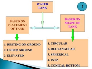
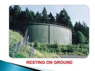
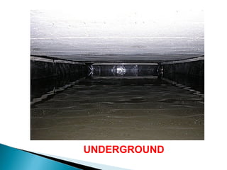
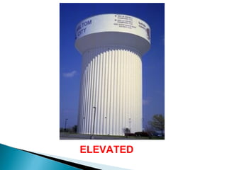
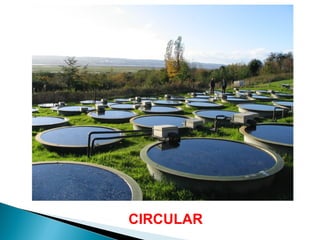
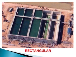
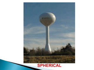
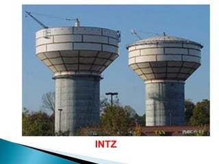
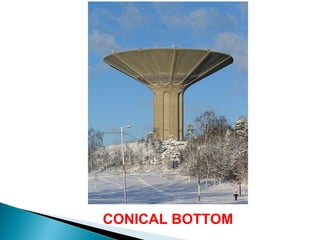
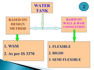
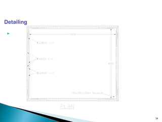
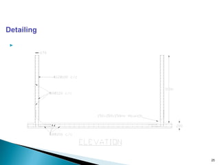
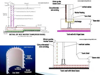
WATER TANKWATER TANK
Department Of Civil Engineering
Shreeyash College Of Engineering And Technology,
Aurangabad, Maharashtra.
Presenting by
Prof. Umesh S. Salunkhe
[Ph. D. (Sch) & M.E. in (Structure ), B.Tech. (Civil), DCE
1. Defn
2. Classification
3. Types
4. Shapes
5. Underground Water Tank
6. Resting on Ground
7. Elevated Store Reserviour
8. IS Code Method
9. WSM
?
?
?
?
?
?
?
?
?
INTRODUCTION
 Storage tanks are built for storing water, liquid
petroleum, petroleum products and similar
liquids
 Designed as crack free structures to eliminate
any leakage
 A crack width of 0.1mm has been accepted as
permissible value in liquid retaining structures
 Cement content ranging from 330 Kg/m3
to 530
Kg/m3
is recommended in order to keep
shrinkage low.
 Code of Practice for the storage of Liquids-
IS3370 (Part I to IV)
 Fractured strength of concrete is computed
using the formula given in clause 6.2.2 of IS 456
-2000 ie., fcr=Sq. Root of 0.7fck MPa.
 Allowable stresses in reinforcing steel as per IS
3370 are
 σst = 115 MPa for Mild steel (Fe250) and
 σst = 150 MPa for HYSD bars(Fe415)
 In order to minimize cracking due to
shrinkage and temperature, minimum
reinforcement is recommended as:
 For thickness (t) 100 mm = 0.3 %
 For thickness (t) 450 mm = 0.2%
 For thickness between 100 mm to 450 mm =
varies linearly from 0.3% to 0.2%
 For concrete thickness (t) 225 mm, two
layers of reinforcement be placed, one near
water face and other away from water face.
 Cover to reinforcement is greater of
i) 25 mm, ii) Diameter of main bar
 For tension on outer face:
σst = 140 MPa for Mild steel and
σst = 230 MPa for HYSD bars
 For concrete thickness ≥ 225 mm, two
layers of reinforcement be placed, one
near water face and other away from
water face.
WATER
TANK
BASED ON
PLACEMENT
OF TANK
BASED ON
SHAPE OF
TANK
1. RESTING ON GROUND
2. UNDER GROUND
3. ELEVATED
1. CIRCULAR
2. RECTANGULAR
3. SPHERICAL
4. INTZ
5. CONICAL BOTTOM
1
RESTING ON GROUND
UNDERGROUND
ELEVATED
CIRCULAR
RECTANGULAR
SPHERICAL
INTZ
CONICAL BOTTOM
WATER
TANK
BASED ON
DESIGN
METHOD
BASED ON
WALL & BASE
CONNCETION
1. WSM
2. As per IS 3370
1. FLEXIBLE
2. RIGID
3. SEMI FLEXIBLE
2
17
 Rectangular tanks are used when the storage
capacity is small
 Rectangular tanks should be preferably square in
plan from point of view of economy.
 It is also desirable that longer side should not be
greater than twice the smaller side.
 Moments are caused in two directions of the wall
i.e., both in horizontal as well as in vertical
direction
 The walls are designed both for direct tension
and bending moment. 18
 When the height is large in comparison to its length,
the moments will be in the horizontal direction and
panel bends as a thin slab supported on edges.
 For intermediate condition bending takes place both
in horizontal and vertical direction.
 In addition to the moments, the walls are also
subjected to direct pull exerted by water pressure
on some portion of walls.
 When the length of the wall is more in comparison
to its height, the moments will be mainly in the
vertical direction, i.e., the panel bends as vertical
cantilever . 19
 IS3370 (Part-IV) gives tables for moments and
shear forces in walls for certain edge condition.
 IS3370 provides coefficient for max Bending
moments in horizontal and vertical direction.
21

22

23
• The slab is resting on firm ground. Hence
nominal thickness and reinforcement is
provided. The thickness of slab is
assumed to be 200 mm and 0.24%
reinforcement is provided in the form of #8
@ 200 c/c. at top and bottom
• A haunch of 150 x 150 x 150 mm size is
provided at all corners

24

25
27
Prof. U. S. salunkhe
Civil Engineering Department
SYCET
Aurangabad- 431010
Mob: 9595576676 / 8484033324
Email:
umeshcivil@gmail.com
umesh.salunkhe@sycet.org

Water tank

  • 1.
    WATER TANKWATER TANK DepartmentOf Civil Engineering Shreeyash College Of Engineering And Technology, Aurangabad, Maharashtra. Presenting by Prof. Umesh S. Salunkhe [Ph. D. (Sch) & M.E. in (Structure ), B.Tech. (Civil), DCE
  • 2.
    1. Defn 2. Classification 3.Types 4. Shapes 5. Underground Water Tank 6. Resting on Ground 7. Elevated Store Reserviour 8. IS Code Method 9. WSM ? ? ? ? ? ? ? ? ?
  • 3.
    INTRODUCTION  Storage tanksare built for storing water, liquid petroleum, petroleum products and similar liquids  Designed as crack free structures to eliminate any leakage  A crack width of 0.1mm has been accepted as permissible value in liquid retaining structures  Cement content ranging from 330 Kg/m3 to 530 Kg/m3 is recommended in order to keep shrinkage low.
  • 4.
     Code ofPractice for the storage of Liquids- IS3370 (Part I to IV)  Fractured strength of concrete is computed using the formula given in clause 6.2.2 of IS 456 -2000 ie., fcr=Sq. Root of 0.7fck MPa.  Allowable stresses in reinforcing steel as per IS 3370 are  σst = 115 MPa for Mild steel (Fe250) and  σst = 150 MPa for HYSD bars(Fe415)
  • 5.
     In orderto minimize cracking due to shrinkage and temperature, minimum reinforcement is recommended as:  For thickness (t) 100 mm = 0.3 %  For thickness (t) 450 mm = 0.2%  For thickness between 100 mm to 450 mm = varies linearly from 0.3% to 0.2%  For concrete thickness (t) 225 mm, two layers of reinforcement be placed, one near water face and other away from water face.
  • 6.
     Cover toreinforcement is greater of i) 25 mm, ii) Diameter of main bar  For tension on outer face: σst = 140 MPa for Mild steel and σst = 230 MPa for HYSD bars  For concrete thickness ≥ 225 mm, two layers of reinforcement be placed, one near water face and other away from water face.
  • 7.
    WATER TANK BASED ON PLACEMENT OF TANK BASEDON SHAPE OF TANK 1. RESTING ON GROUND 2. UNDER GROUND 3. ELEVATED 1. CIRCULAR 2. RECTANGULAR 3. SPHERICAL 4. INTZ 5. CONICAL BOTTOM 1
  • 8.
  • 9.
  • 10.
  • 11.
  • 12.
  • 13.
  • 14.
  • 15.
  • 16.
    WATER TANK BASED ON DESIGN METHOD BASED ON WALL& BASE CONNCETION 1. WSM 2. As per IS 3370 1. FLEXIBLE 2. RIGID 3. SEMI FLEXIBLE 2
  • 17.
  • 18.
     Rectangular tanksare used when the storage capacity is small  Rectangular tanks should be preferably square in plan from point of view of economy.  It is also desirable that longer side should not be greater than twice the smaller side.  Moments are caused in two directions of the wall i.e., both in horizontal as well as in vertical direction  The walls are designed both for direct tension and bending moment. 18
  • 19.
     When theheight is large in comparison to its length, the moments will be in the horizontal direction and panel bends as a thin slab supported on edges.  For intermediate condition bending takes place both in horizontal and vertical direction.  In addition to the moments, the walls are also subjected to direct pull exerted by water pressure on some portion of walls.  When the length of the wall is more in comparison to its height, the moments will be mainly in the vertical direction, i.e., the panel bends as vertical cantilever . 19
  • 21.
     IS3370 (Part-IV)gives tables for moments and shear forces in walls for certain edge condition.  IS3370 provides coefficient for max Bending moments in horizontal and vertical direction. 21
  • 22.
  • 23.
     23 • The slabis resting on firm ground. Hence nominal thickness and reinforcement is provided. The thickness of slab is assumed to be 200 mm and 0.24% reinforcement is provided in the form of #8 @ 200 c/c. at top and bottom • A haunch of 150 x 150 x 150 mm size is provided at all corners
  • 24.
  • 25.
  • 27.
    27 Prof. U. S.salunkhe Civil Engineering Department SYCET Aurangabad- 431010 Mob: 9595576676 / 8484033324 Email: umeshcivil@gmail.com umesh.salunkhe@sycet.org