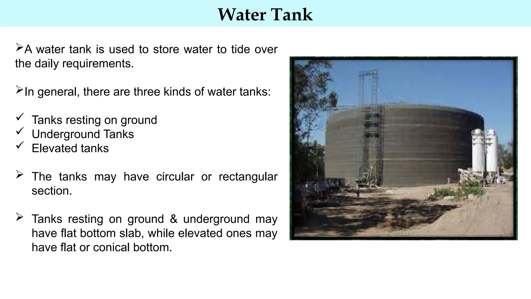
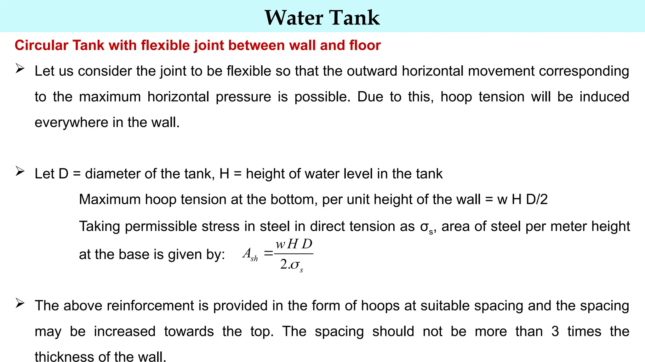
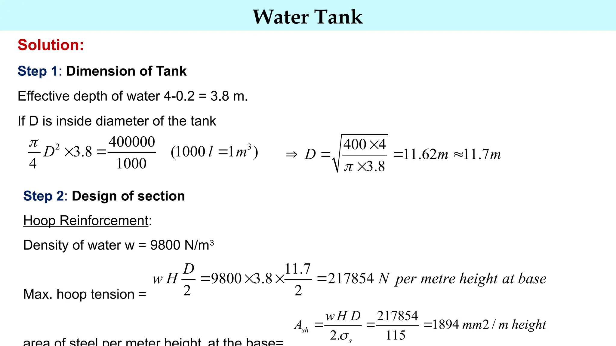
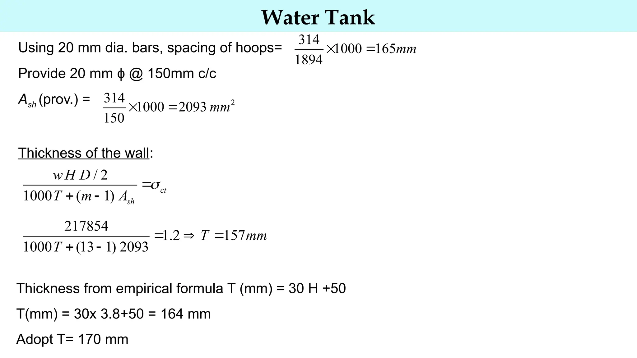
Water Tank
Water Tank
A water tank is used to store water to tide over
the daily requirements.
In general, there are three kinds of water tanks:
 Tanks resting on ground
 Underground Tanks
 Elevated tanks
 The tanks may have circular or rectangular
section.
 Tanks resting on ground & underground may
have flat bottom slab, while elevated ones may
have flat or conical bottom.
Water Tank
General Requirements (IS 3370- Part II, 1965)
1. Concrete should be impervious- Concrete should be rich in cement content i.e. water-
cement ratio should be low. The quantity of cement in mix should not be less than 3 KN/m³,
again to keep shrinkage low the quantity of cement should not exceed 5.3 KN/m³.For water
tanks concrete grade M20 or greater is used.
2. Permissible Stresses
(a) For crack resistance
(b) For strength calculation
Water Tank
Grade of
Concrete
Permissible Stress
in Direct Tension
(N/mm²)
Permissible Stress
in tension due to
bending
(N/mm²)
Permissible stress
in shear
(N/mm²)
M 15 1.1 1.5 1.5
M 20 1.2 1.7 1.7
M 25 1.3 1.8 1.9
M 30 1.5 2.0 2.2
M 35 1.6 2.2 2.5
Permissible Stresses in concrete for crack Resistance: IS 456-2000 does not specify the permissible
stresses in concrete for its resistance to cracking. However, IS 456-1964 included the permissible
stresses in direct tension, bending tension and shear.
Water Tank
Type of stress in steel
reinforcement
Permissible Stress in
(N/mm²)
Plain round mild steel
bars
High yield strength deformed
bars (HYSD)
1)Tensile stresses in the
members under direct
tension(σs)
115 150
2) Tensile stress in members
in bending(σst)
On liquid retaining face of
members
115 150
On face of away from liquid
for members
less than 225mm
115 150
On face away from liquid for
members 225mm or more in
thickness
125 190
Permissible stresses in steel for strength calculation
Water Tank
Circular Tank
 Circular tank with flexible joint between wall and slab
 Circular tank with rigid joint between wall and slab
Circular Tank with flexible joint between wall and floor
 When water is filled in circular tank, hydrostatic water pressure will try to increase its diameter
at any section. However, this increase in diameter all along the height of the tank will depend
upon the nature of the joint at the junction B of the wall and bottom slab. If the joint at B is
flexible (i.e. sliding joint). It will be free to move outward to a position B1. the hydrostatic
pressure at A is zero, and hence there will be no change in the diameter at A.
Water Tank
Circular Tank with flexible joint between wall and floor
 Let us consider the joint to be flexible so that the outward horizontal movement corresponding
to the maximum horizontal pressure is possible. Due to this, hoop tension will be induced
everywhere in the wall.
 Let D = diameter of the tank, H = height of water level in the tank
Maximum hoop tension at the bottom, per unit height of the wall = w H D/2
Taking permissible stress in steel in direct tension as σs, area of steel per meter height
at the base is given by:
 The above reinforcement is provided in the form of hoops at suitable spacing and the spacing
may be increased towards the top. The spacing should not be more than 3 times the
thickness of the wall.
2.
sh
s
wH D
A 

Water Tank
 Thickness of wall: Though the reinforcement has been provided to take the entire hoop
tension, the concrete has not been prevented to take part of this tension. The thickness of the
wall should, therefore, be such that the tensile stress developed in the composite section is
within safe limit. If σct is the permissible tensile stress in the equivalent concrete section, T is
the thickness of the wall, we have
( 1)
ct ct
c st st
F F
A m A A m A
  
  
 
/ 2
1000 ( 1)
ct
sh
wH D
value of T can be obtained from this equation
T m A
 
 

Thickness should also be checked by the following empirical formula:
T (mm) = 30 H +50, where H is the height of water in metres
Water Tank
 Minimum reinforcement: For thickness up to 100mm, minimum % of reinforcement should be
0.3%. For thickness from 100mm to 450mm, it may be reduced linearly to 0.2%
Minimum reinforcement should be ensured in both directions.
 For thickness 225mm or greater, two layers of reinforcing bars shall be placed, one near each
of the section.
 For floor slab minimum reinforcement should be 0.15% of concrete section.
 Minimum cover should be 25mm or diameter of the bar, whichever is greater.
Water Tank
Problem 1: Design a circular water tank with flexible base for capacity of 400000
litres. The depth of water is to be 4 m, including a free board of 200 mm. Use M20
concrete and mild steel bars.
Water Tank
Solution:
Step 1: Dimension of the tank
Step 2: Design of section
Step 3: Vertical Reinforcement
Step 4: Design of tank floor
Step 5: Details of reinforcement
Water Tank
Solution:
Step 1: Dimension of Tank
Effective depth of water 4-0.2 = 3.8 m.
If D is inside diameter of the tank
2 3
400000
3.8 (1000 1 )
4 1000
D l m
  
 400 4
11.62 11.7
3.8
D m m

   


Step 2: Design of section
Hoop Reinforcement:
Density of water w = 9800 N/m3
Max. hoop tension =
11.7
9800 3.8 217854
2 2
D
w H N per metre height at base
   
217854
1894 2 /
2. 115
sh
s
wH D
A mm m height
  

Water Tank
Using 20 mm dia. bars, spacing of hoops=
Provide 20 mm ϕ @ 150mm c/c
Ash (prov.) =
Thickness of the wall:
314
1000 165
1894
mm
 
2
314
1000 2093
150
mm
 
/ 2
1000 ( 1)
ct
sh
wH D
T m A

 

217854
1.2 157
1000 (13 1) 2093
T mm
T
  
 
Thickness from empirical formula T (mm) = 30 H +50
T(mm) = 30x 3.8+50 = 164 mm
Adopt T= 170 mm
Water Tank
Reinforcement:
 Hoop reinforcement at bottom 20 mm ϕ @ 150mm c/c
 For spacing 200mm, Area of hoop reinforcement
Height from top
 For spacing 300mm, Area of hoop reinforcement
Height from top
/ 2 115 1570
3.14
115 9800 11.7 / 2
sh
w H D
A H m

   

2
1000 314
1570
200
mm


2
1000 314
1046
300
mm


/ 2 115 1046
2.09
115 9800 11.7 / 2
sh
w H D
A H m

   

Water Tank
Spacing of hoops can be increased near the top. Providing a minimum reinforcement of 0.3%
at the top.
Spacing of hoops =
However, spacing of hoops should not be more than 3 times of thickness of the wall, which
gives: Spacing = 170 x 3 =510mm
Hence provide spacing 500 mm c/c at the top.
2
0.3
(1000 170) 510
100
sh
A mm
  
1000 314
600
510
mm


Since the thickness of the wall is less than 225 mm, reinforcement will be provided at the centre
of the thickness.
Water Tank
Step 3: Vertical Reinforcement
Distribution and temperature reinforcement is provided in the vertical direction and its area is
(by interpolation) =
170 100
0.3 0.1 0.28%
350

   
2
0.28
(1000 170) 476
100
sv
A mm
  
Using 10 mm dia. Bars, spacing =
Provide 10 mm ϕ @ 160mm c/c
78.5
1000 165
476
mm
 
Water Tank
Step 4: Design of tank floor
Since the tank floor is resting on the ground throughout, provide a nominal thickness of
150mm
Minimum reinforcement
Providing half the reinforcement near each face =225 mm2
2
0.3
(1000 150) 450
100
st
A mm in each direction
  
Using 8 mm dia. Bars, spacing =
Provide 8 mm ϕ @ 200mm c/c in both direction, at top and bottom of the floor slab
50
1000 220
225
mm
 
Water Tank
Step 4: Detailing

Water Tank Design civil engineering.pptx

  • 1.
  • 2.
    Water Tank A watertank is used to store water to tide over the daily requirements. In general, there are three kinds of water tanks:  Tanks resting on ground  Underground Tanks  Elevated tanks  The tanks may have circular or rectangular section.  Tanks resting on ground & underground may have flat bottom slab, while elevated ones may have flat or conical bottom.
  • 3.
    Water Tank General Requirements(IS 3370- Part II, 1965) 1. Concrete should be impervious- Concrete should be rich in cement content i.e. water- cement ratio should be low. The quantity of cement in mix should not be less than 3 KN/m³, again to keep shrinkage low the quantity of cement should not exceed 5.3 KN/m³.For water tanks concrete grade M20 or greater is used. 2. Permissible Stresses (a) For crack resistance (b) For strength calculation
  • 4.
    Water Tank Grade of Concrete PermissibleStress in Direct Tension (N/mm²) Permissible Stress in tension due to bending (N/mm²) Permissible stress in shear (N/mm²) M 15 1.1 1.5 1.5 M 20 1.2 1.7 1.7 M 25 1.3 1.8 1.9 M 30 1.5 2.0 2.2 M 35 1.6 2.2 2.5 Permissible Stresses in concrete for crack Resistance: IS 456-2000 does not specify the permissible stresses in concrete for its resistance to cracking. However, IS 456-1964 included the permissible stresses in direct tension, bending tension and shear.
  • 5.
    Water Tank Type ofstress in steel reinforcement Permissible Stress in (N/mm²) Plain round mild steel bars High yield strength deformed bars (HYSD) 1)Tensile stresses in the members under direct tension(σs) 115 150 2) Tensile stress in members in bending(σst) On liquid retaining face of members 115 150 On face of away from liquid for members less than 225mm 115 150 On face away from liquid for members 225mm or more in thickness 125 190 Permissible stresses in steel for strength calculation
  • 6.
    Water Tank Circular Tank Circular tank with flexible joint between wall and slab  Circular tank with rigid joint between wall and slab Circular Tank with flexible joint between wall and floor  When water is filled in circular tank, hydrostatic water pressure will try to increase its diameter at any section. However, this increase in diameter all along the height of the tank will depend upon the nature of the joint at the junction B of the wall and bottom slab. If the joint at B is flexible (i.e. sliding joint). It will be free to move outward to a position B1. the hydrostatic pressure at A is zero, and hence there will be no change in the diameter at A.
  • 7.
    Water Tank Circular Tankwith flexible joint between wall and floor  Let us consider the joint to be flexible so that the outward horizontal movement corresponding to the maximum horizontal pressure is possible. Due to this, hoop tension will be induced everywhere in the wall.  Let D = diameter of the tank, H = height of water level in the tank Maximum hoop tension at the bottom, per unit height of the wall = w H D/2 Taking permissible stress in steel in direct tension as σs, area of steel per meter height at the base is given by:  The above reinforcement is provided in the form of hoops at suitable spacing and the spacing may be increased towards the top. The spacing should not be more than 3 times the thickness of the wall. 2. sh s wH D A  
  • 8.
    Water Tank  Thicknessof wall: Though the reinforcement has been provided to take the entire hoop tension, the concrete has not been prevented to take part of this tension. The thickness of the wall should, therefore, be such that the tensile stress developed in the composite section is within safe limit. If σct is the permissible tensile stress in the equivalent concrete section, T is the thickness of the wall, we have ( 1) ct ct c st st F F A m A A m A         / 2 1000 ( 1) ct sh wH D value of T can be obtained from this equation T m A      Thickness should also be checked by the following empirical formula: T (mm) = 30 H +50, where H is the height of water in metres
  • 9.
    Water Tank  Minimumreinforcement: For thickness up to 100mm, minimum % of reinforcement should be 0.3%. For thickness from 100mm to 450mm, it may be reduced linearly to 0.2% Minimum reinforcement should be ensured in both directions.  For thickness 225mm or greater, two layers of reinforcing bars shall be placed, one near each of the section.  For floor slab minimum reinforcement should be 0.15% of concrete section.  Minimum cover should be 25mm or diameter of the bar, whichever is greater.
  • 10.
    Water Tank Problem 1:Design a circular water tank with flexible base for capacity of 400000 litres. The depth of water is to be 4 m, including a free board of 200 mm. Use M20 concrete and mild steel bars.
  • 11.
    Water Tank Solution: Step 1:Dimension of the tank Step 2: Design of section Step 3: Vertical Reinforcement Step 4: Design of tank floor Step 5: Details of reinforcement
  • 12.
    Water Tank Solution: Step 1:Dimension of Tank Effective depth of water 4-0.2 = 3.8 m. If D is inside diameter of the tank 2 3 400000 3.8 (1000 1 ) 4 1000 D l m     400 4 11.62 11.7 3.8 D m m        Step 2: Design of section Hoop Reinforcement: Density of water w = 9800 N/m3 Max. hoop tension = 11.7 9800 3.8 217854 2 2 D w H N per metre height at base     217854 1894 2 / 2. 115 sh s wH D A mm m height    
  • 13.
    Water Tank Using 20mm dia. bars, spacing of hoops= Provide 20 mm ϕ @ 150mm c/c Ash (prov.) = Thickness of the wall: 314 1000 165 1894 mm   2 314 1000 2093 150 mm   / 2 1000 ( 1) ct sh wH D T m A     217854 1.2 157 1000 (13 1) 2093 T mm T      Thickness from empirical formula T (mm) = 30 H +50 T(mm) = 30x 3.8+50 = 164 mm Adopt T= 170 mm
  • 14.
    Water Tank Reinforcement:  Hoopreinforcement at bottom 20 mm ϕ @ 150mm c/c  For spacing 200mm, Area of hoop reinforcement Height from top  For spacing 300mm, Area of hoop reinforcement Height from top / 2 115 1570 3.14 115 9800 11.7 / 2 sh w H D A H m       2 1000 314 1570 200 mm   2 1000 314 1046 300 mm   / 2 115 1046 2.09 115 9800 11.7 / 2 sh w H D A H m      
  • 15.
    Water Tank Spacing ofhoops can be increased near the top. Providing a minimum reinforcement of 0.3% at the top. Spacing of hoops = However, spacing of hoops should not be more than 3 times of thickness of the wall, which gives: Spacing = 170 x 3 =510mm Hence provide spacing 500 mm c/c at the top. 2 0.3 (1000 170) 510 100 sh A mm    1000 314 600 510 mm   Since the thickness of the wall is less than 225 mm, reinforcement will be provided at the centre of the thickness.
  • 16.
    Water Tank Step 3:Vertical Reinforcement Distribution and temperature reinforcement is provided in the vertical direction and its area is (by interpolation) = 170 100 0.3 0.1 0.28% 350      2 0.28 (1000 170) 476 100 sv A mm    Using 10 mm dia. Bars, spacing = Provide 10 mm ϕ @ 160mm c/c 78.5 1000 165 476 mm  
  • 17.
    Water Tank Step 4:Design of tank floor Since the tank floor is resting on the ground throughout, provide a nominal thickness of 150mm Minimum reinforcement Providing half the reinforcement near each face =225 mm2 2 0.3 (1000 150) 450 100 st A mm in each direction    Using 8 mm dia. Bars, spacing = Provide 8 mm ϕ @ 200mm c/c in both direction, at top and bottom of the floor slab 50 1000 220 225 mm  
  • 18.