This document provides guidance on designing rectangular concrete tanks. It discusses:
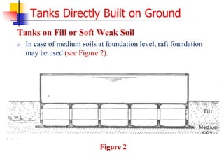
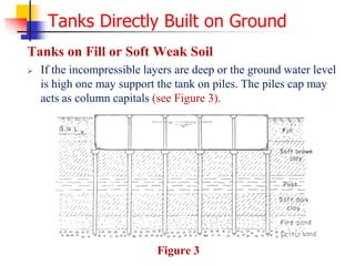
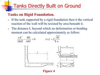
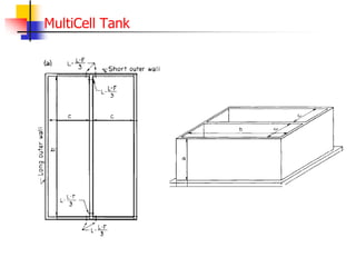
- Rectangular tanks are commonly used where partitions or multiple cells are needed, though cylinders are structurally superior.
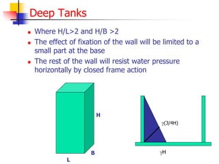
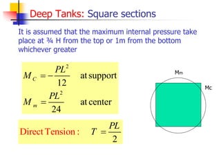
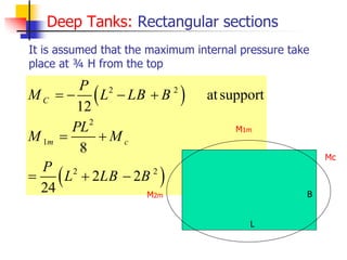
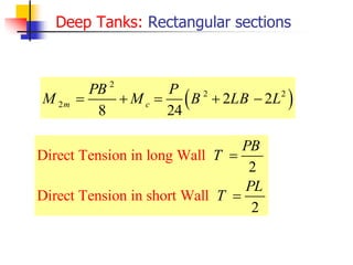
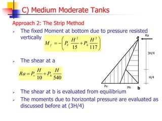
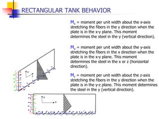
- The behavior of rectangular tanks differs from circular tanks due to non-uniform stresses. Moments, shears, and tensions must be specifically calculated.
- The design process for rectangular tanks is similar to circular tanks, considering the same loading combinations and structural requirements.
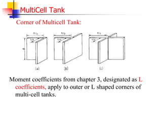
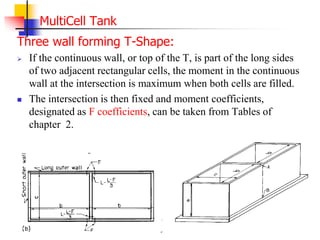
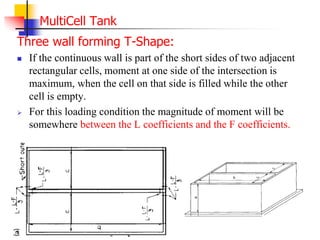
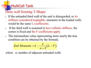
- Examples are provided to demonstrate calculating shear, moment, and reinforcement requirements for rectangular tank walls and slabs. Guidance is given for multi-cell tank junctions.


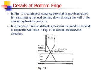
![42
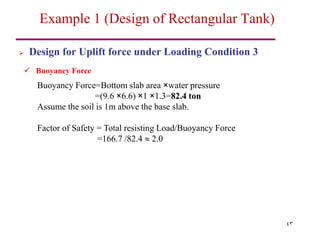
Design for Uplift force under Loading Condition 3
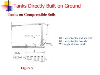
Weight of the Tank
The weight of the slab and walls as well as the soil resting on the footing
projection must be capable of resisting the upward force of water.
Walls = height × length × thickness × 2.5 t/m3
=3 ×(9+9+6+6) ×0.3 ×2.5=67.5 ton
Bottom slab = length × width × thickness × 2.5 t/m3
=(9+0.6)×(6+0.6) ×0.3 ×2.5=47.5 ton
Top slab = length × width × thickness × 2.5 t/m3
=(9)×(6) ×0.3 ×2.5=40.5 ton
Soil on footing overhang =soil area ×soil height × 1.2 t/m3
=[(9.6 ×6.6)-(9 ×6)] ×1 ×1.2=11.2 ton
Total Resisting Load =67.5+47.5+40.5+11.2 =166.7 ton
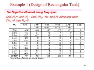
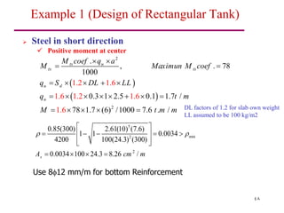
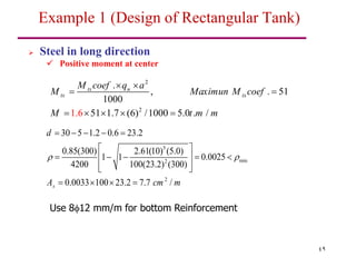
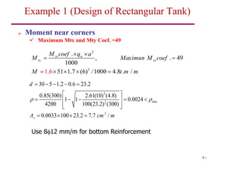
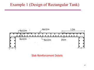
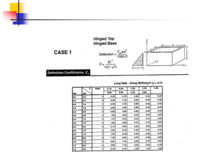
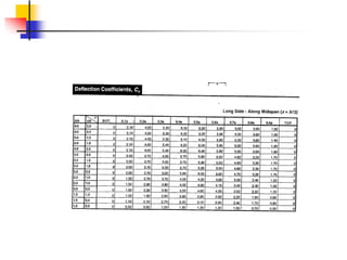
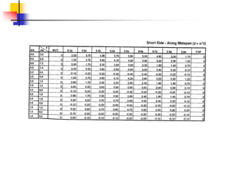
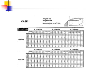
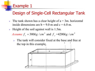
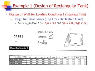
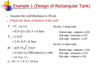
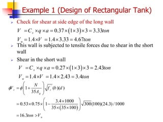
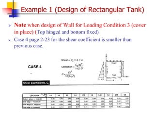
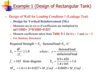
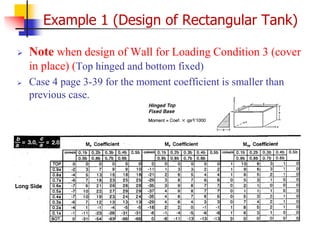
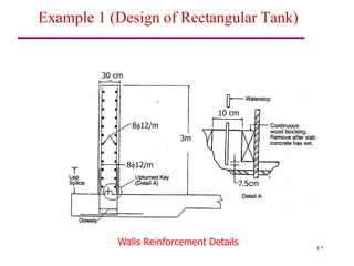
Example 1 (Design of Rectangular Tank)](https://image.slidesharecdn.com/exrectangulartanks-25-3-2015-220926041613-a454665c/85/ExRectangularTanks-25-3-2015-pdf-42-320.jpg)