Download to read offline

![Location: Kalyani
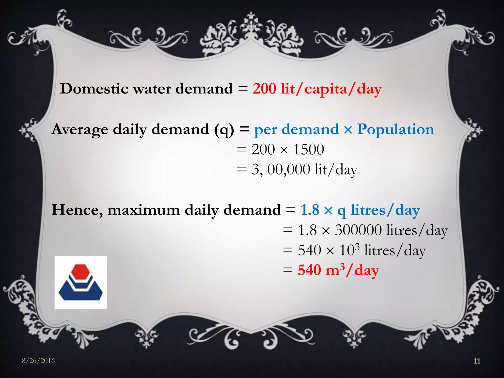
Target Population: 1500
Maximum daily consumption (demand)
=180% of average daily demand = 1.8q
[Ref: Water Supply Engineering by S.K.Garg, Page-19]
8/26/2016 10](https://image.slidesharecdn.com/abhijitkumar-160826192300/75/Abhijit-kumar-10-2048.jpg)
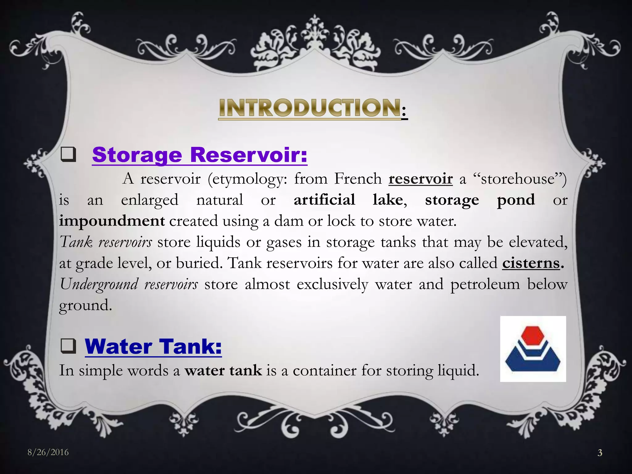
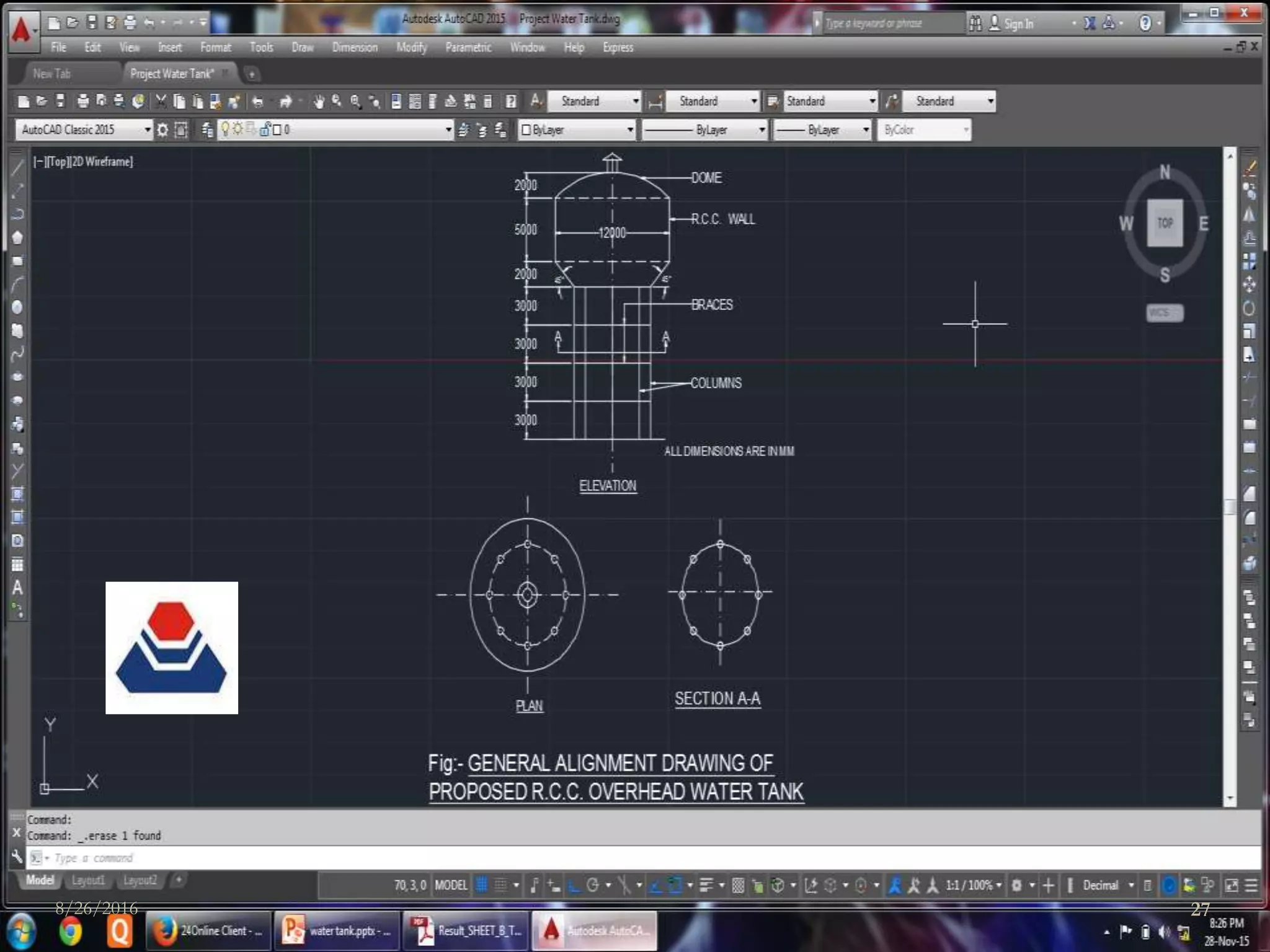
![Let us assume, diameter of tank (D) = 12m (< 30m)
[as per Clause 7.2.1.1 of IS:2210-1988, page 8]
Hence, radius of tank (R) = 12/2 = 6m.
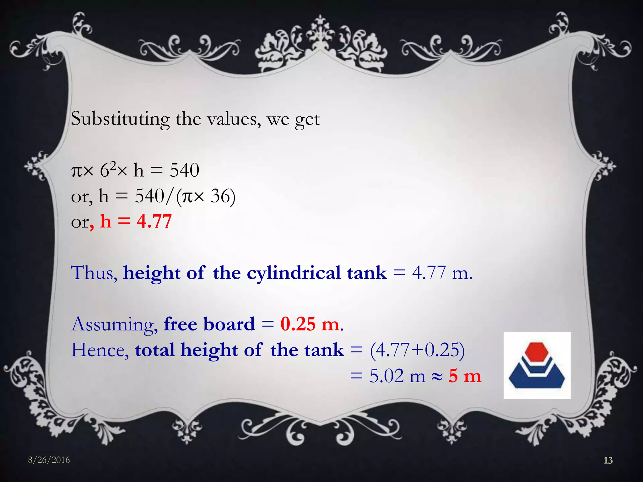
Now, volume of tank = 540 m3.
Let h be the height of the cylindrical tank.
Capacity of tank = R2 h
8/26/2016 12](https://image.slidesharecdn.com/abhijitkumar-160826192300/75/Abhijit-kumar-12-2048.jpg)
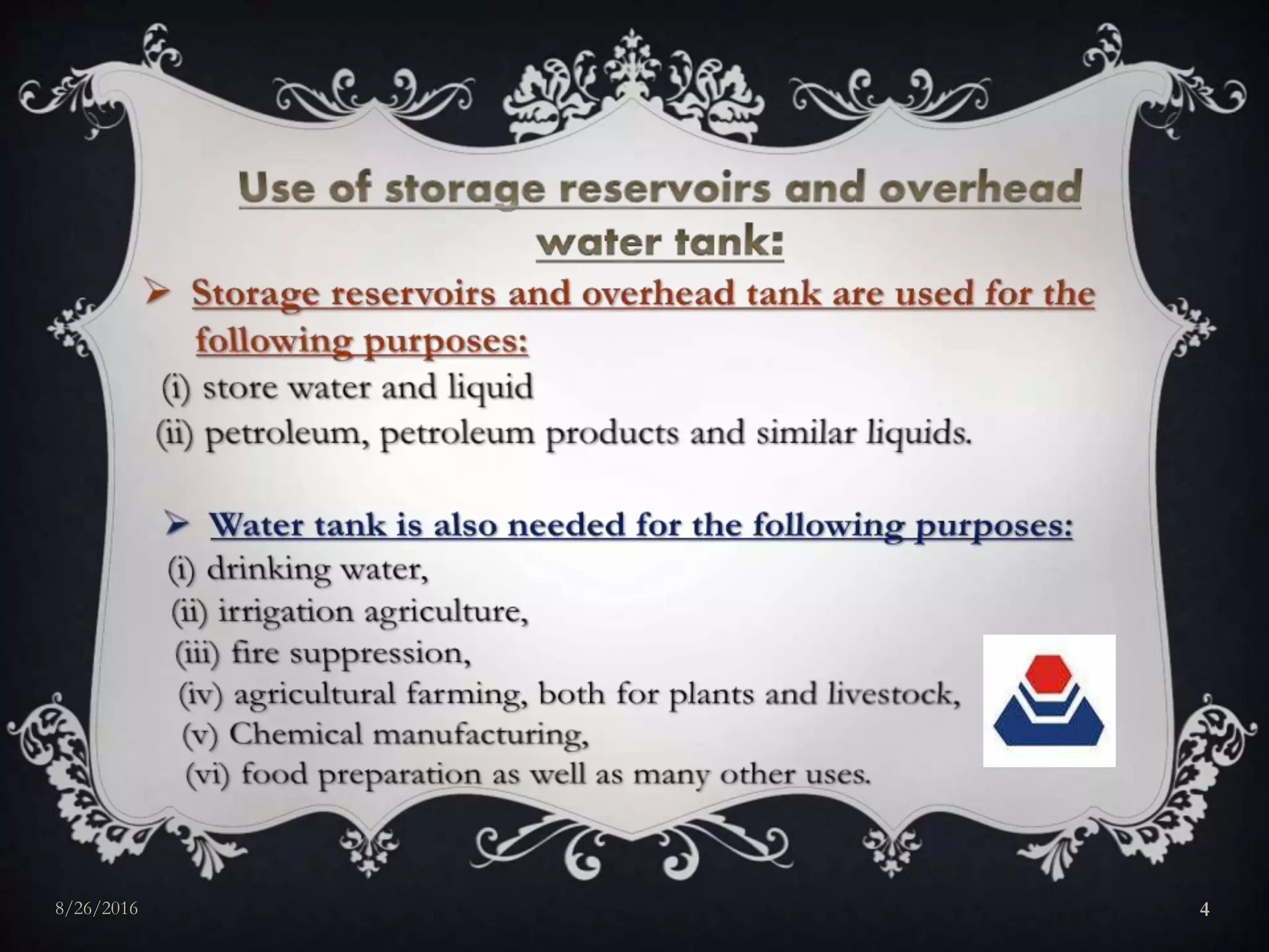
![D
r
A C B
R1 R1
O
Notations:
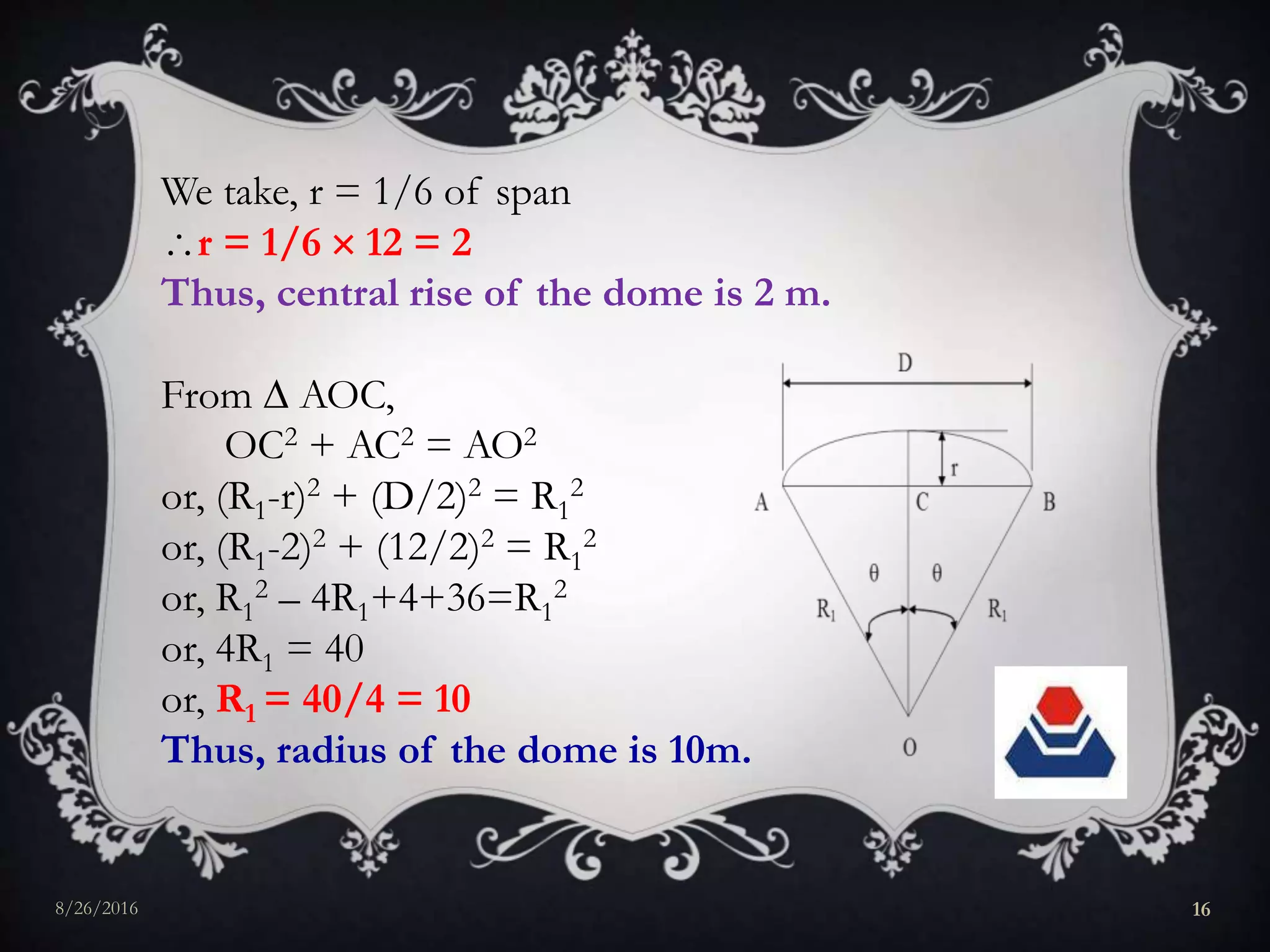
D = Diameter of the tank = 12m
r = Central rise of the dome
R1= Radius of the dome
= Semi-central angle of the dome
From the geometry of the figure,
AOC & BOC are right-angled triangles.
Central rise, r = 1/8 to 1/6 of span
[Ref: Advanced Reinforced Concrete by H.J.Shah, page-406]
8/26/2016 15](https://image.slidesharecdn.com/abhijitkumar-160826192300/75/Abhijit-kumar-15-2048.jpg)
![Again, cos = = = = 0.8
or, = cos-1(0.8)
or, = 36.87
Thus, semi-central angle of the dome is 36.87
30<< 40. Hence, OK.
[as per IS:2210-1988, page-8]
8/26/2016 17](https://image.slidesharecdn.com/abhijitkumar-160826192300/75/Abhijit-kumar-17-2048.jpg)
![Again, = 36.87< 51.8
Hence, tensile stress is not developed.
[Ref: Advanced Reinforced Concrete by H.J Shah,
page 64]
Now, r/D = 2/12 = 1/6 (< 1/5)
[as per IS: 2210-1988, page-10]
So, it is a deep doubly curved shell and membrane
analysis is required.
8/26/2016 18](https://image.slidesharecdn.com/abhijitkumar-160826192300/75/Abhijit-kumar-18-2048.jpg)
![Load calculation:
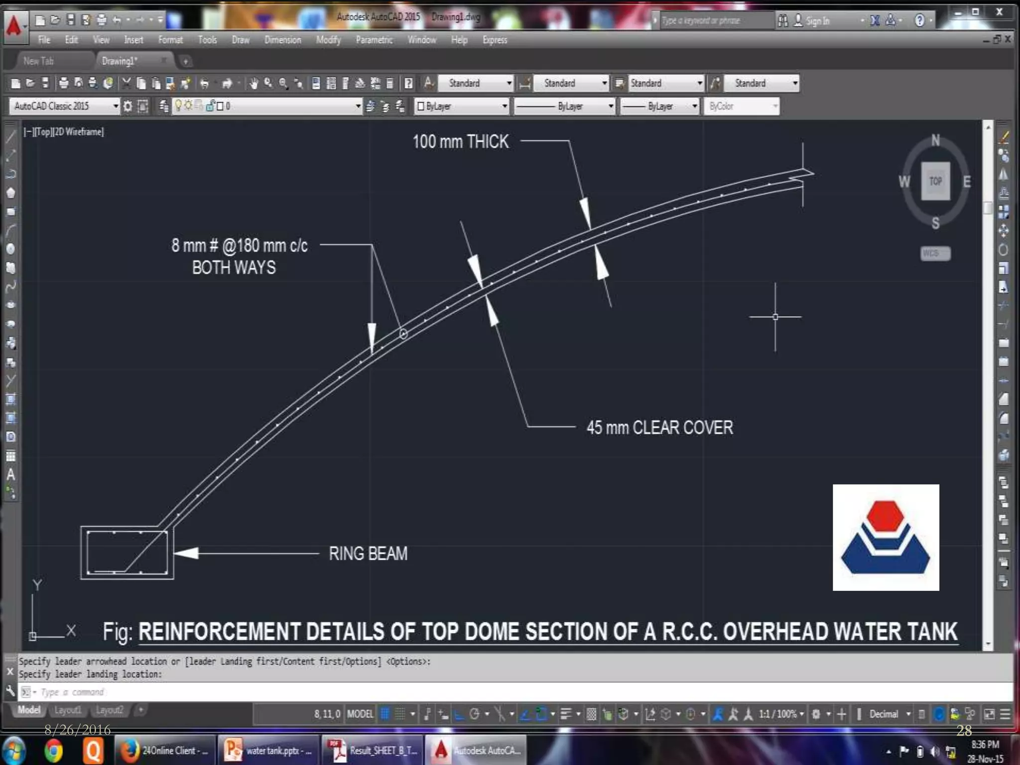
We assume, thickness of top dome = 100 mm ( 40 mm)
[as per Clause 7.1.1 of IS:2210-1988, page-8]
Minimum imposed load for accessible roof = 1.5KN/m2
[as per IS-875 Part-2]
Self-weight of the dome = 0.1 25 = 2.5 KN/m2
Finishing = 0.05 24 = 1.2 KN/m2
___________________________________________________
Total load = (1.5+2.5+1.2) = 5.2 KN/m2
8/26/2016 19](https://image.slidesharecdn.com/abhijitkumar-160826192300/75/Abhijit-kumar-19-2048.jpg)
![Calculation of Meridional stress and Hoop stress:
Meridional force:
Due to UDL =
[Ref: Advanced Reinforced Concrete by H.J Shah, page-64]
Meridional force = 5.2 10
= 28.89 KN.
Meridional stress for per meter span =
= 0.2889 N/mm2
0.29 N/mm2 (compressive)
8/26/2016 20](https://image.slidesharecdn.com/abhijitkumar-160826192300/75/Abhijit-kumar-20-2048.jpg)
![As the minimum grade of concrete is M30, thus for M30
[as per IS-456:2000, Table-21, page-81]
σcc = 8N/mm2
Thus, 0.29 < 8 N/mm2. Hence, OK.
8/26/2016 21](https://image.slidesharecdn.com/abhijitkumar-160826192300/75/Abhijit-kumar-21-2048.jpg)
![Hoop force:
Due to UDL =
[Ref: Advanced Reinforced Concrete by H.J Shah,
page-64]
Hoop force = 5.2 10
= 12.71KN.
Hoop stress for per meter span =
= 0.1271 N/mm2
0.13 N/mm2 (compressive)
Thus, 0.13 < 8 N/mm2. Hence OK.
Hence, the stresses are within the safe limit.
8/26/2016 22](https://image.slidesharecdn.com/abhijitkumar-160826192300/75/Abhijit-kumar-22-2048.jpg)
![Since the stresses are very small, we provide nominal
tensile reinforcement of 0.3%
[as per IS: 3370 (Part-2:2009) page-3, Table-3 the
nominal percentage of nominal tensile reinforcement
shall not be less than 0.15% in any case]
= 0.3
or, Ast = 1000 100
or, Ast = 300 mm2
Thus, area of steel reinforcement is 300 mm2.
8/26/2016 23](https://image.slidesharecdn.com/abhijitkumar-160826192300/75/Abhijit-kumar-23-2048.jpg)
![We provide 6 - 8mm # bars,
[as per clause 12.3.1 of IS: 2210-1988]
Spacing of 8mm # bars = = 167.53 mm
180 mm c/c
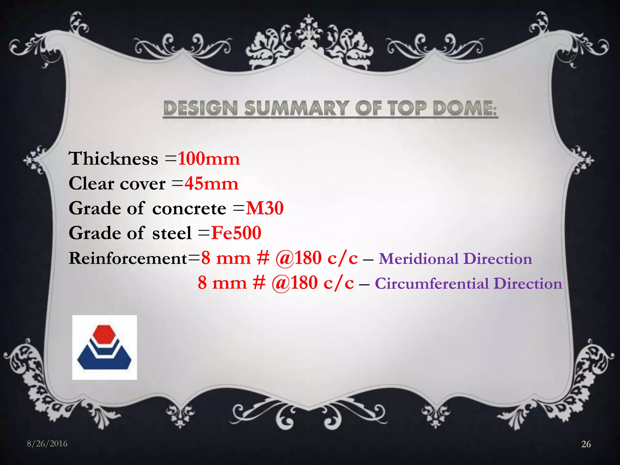
Thus, we provide 6 – 8mm @180mm c/c both ways.
Actual Percentage of steel required (Pt)
= = = 0.30%
8/26/2016 24](https://image.slidesharecdn.com/abhijitkumar-160826192300/75/Abhijit-kumar-24-2048.jpg)
![Clear cover [as per clause 7.1.1.1 of IS: 2210-1988]:-
(i) 15mm.
(ii) Nominal size
whichever is greater.
Now, for severe exposure, nominal cover = 45 mm
[as per Table 16 of IS: 456-2000]
As, 45 > 15mm, so we provide clear cover = 45mm.
8/26/2016 25](https://image.slidesharecdn.com/abhijitkumar-160826192300/75/Abhijit-kumar-25-2048.jpg)
![(i) Water Supply Engineering by S.K.Garg
(ii) IS 2210-1988
(iii) Advanced Reinforced Concrete by H.J.Shah
(iv) IS 875 (Part 1 & 2)
(iv) IS-456:2000
(v) IS: 3370:2009 [Part-2]
(vi) Wikipedia
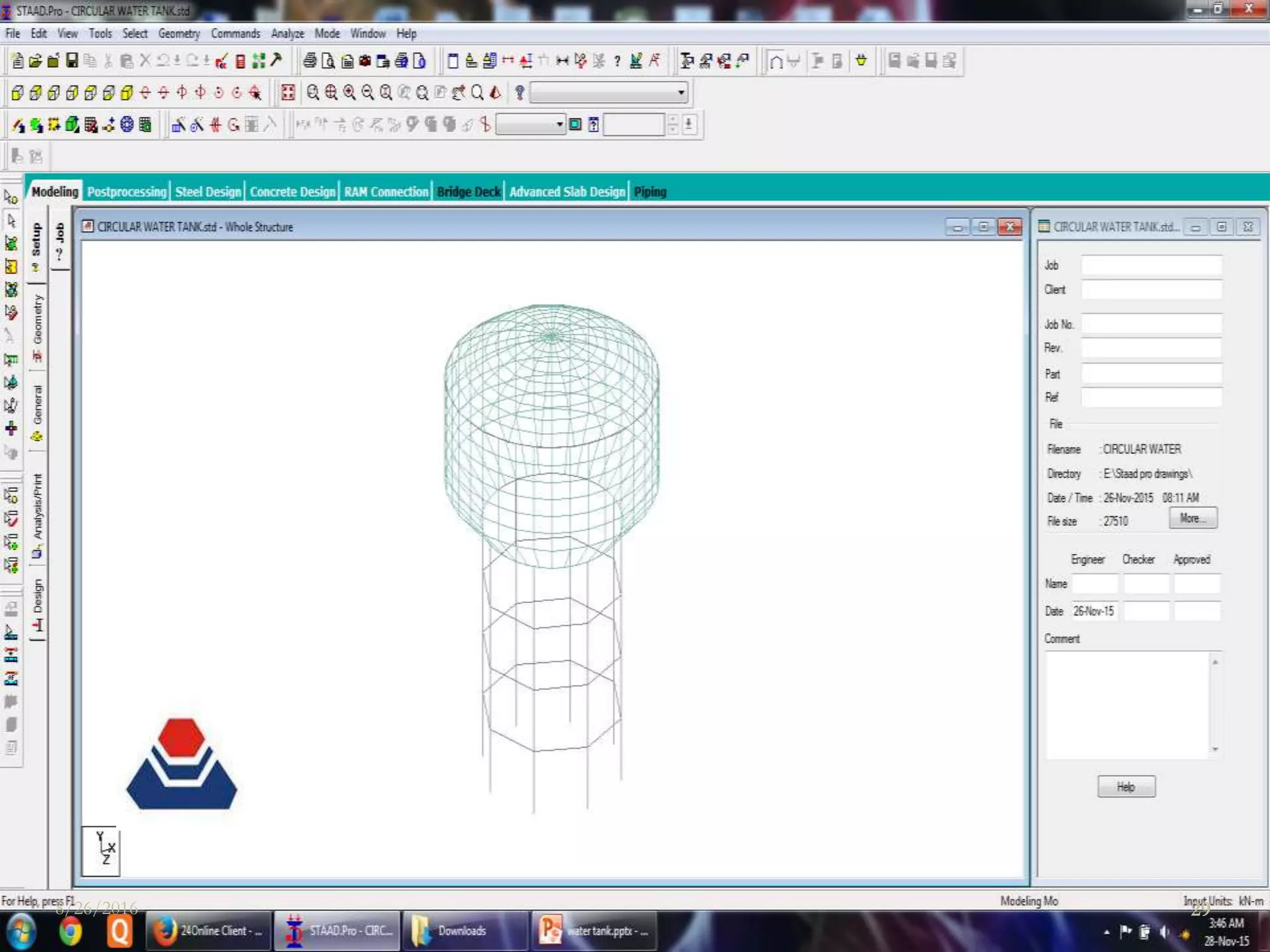
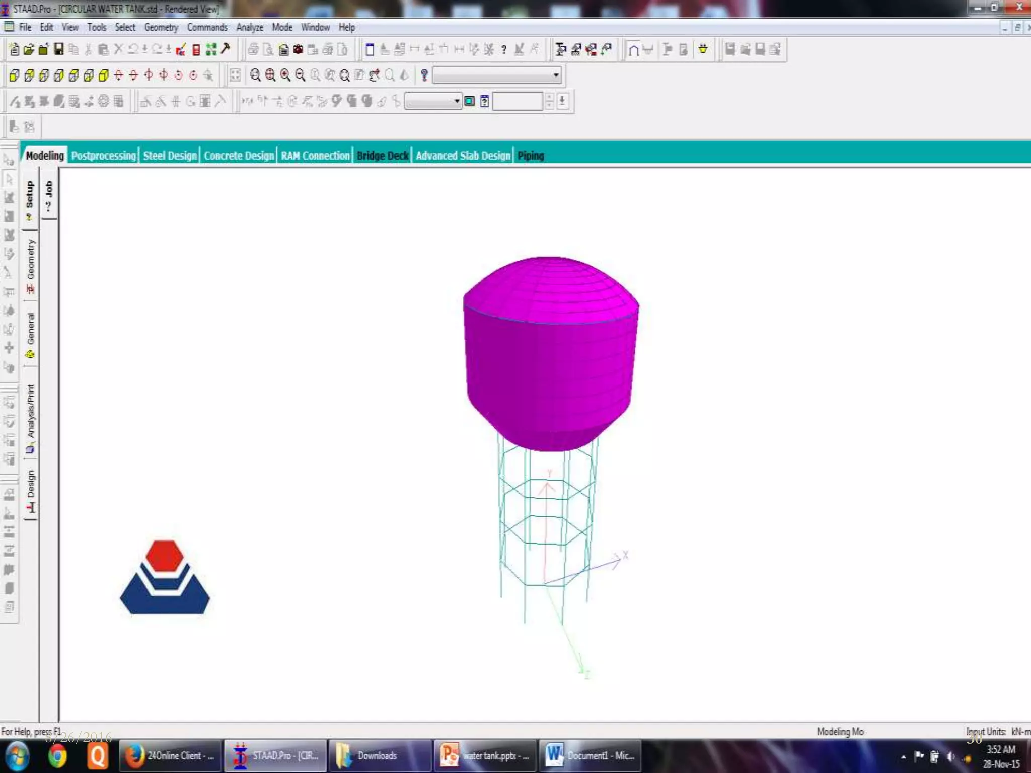
(vii) Softwares – AutoCAD & STAAD.Pro
8/26/2016 31](https://image.slidesharecdn.com/abhijitkumar-160826192300/75/Abhijit-kumar-31-2048.jpg)


The document is a presentation on the design of an overhead water tank located at a railway colony in Allahabad, India. It includes the following key points: - The target population is 1500 people and the maximum daily water demand calculated is 540 cubic meters. - The proposed water tank design has a diameter of 12 meters, height of 5 meters, and volume capacity of 540 cubic meters. - The tank will have a dome roof supported by 8 columns and be constructed of reinforced concrete designed to withstand specified loadings. - Detailed calculations are shown for determining the dome geometry, stresses, and steel reinforcement requirements based on code specifications. - Construction details like raft foundation, concrete grade of M


