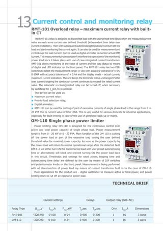
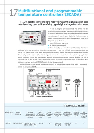
Download to read offline

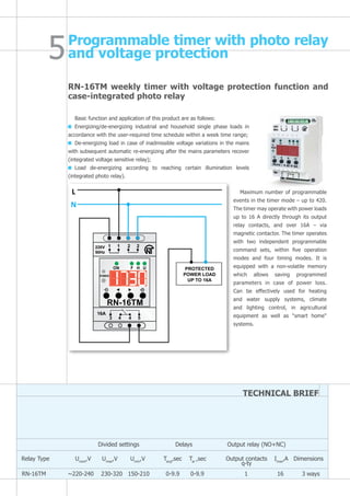

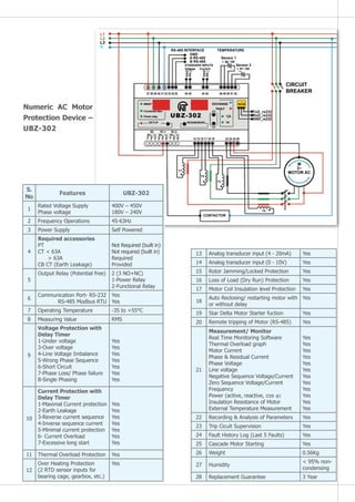
![UBZ-304 Numerical motor protection relay with communication
for SCADA integration
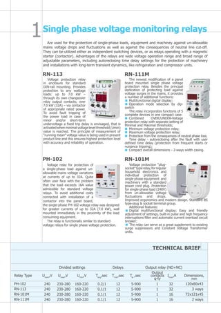
Induction motor protection device
UBZ-304 universal induction electric motor protection unit (“UBZ”) is used for
protection of asynchronous electric motors (2.5 to 315 kW) that use external
standard current transformers with output current 1 A or 5 A (selectable).
UBZ can work in circuits both with neutral or isolated neutral.
Configuration type – 96 x 96 Flush mounting with backlit LCD display and LED.
UBZ provides for constant control of the circuit voltage parameters, effective
values of phase/linear currents of 415V 50 Hz three-phrase electric equipment,
and checks the insulation resistance of electric motors.
UBZ provides for electric motor protection in case of:
Low quality circuit voltage & frequency [extreme voltage surges, phase failures (single phasing), incorrect
phase sequence and imbalance (asymmetry) of phase/line voltage, frequency outside of the given range];
Mechanical overload (symmetric overload of phase/line currents);
Exceeded threshold of negative sequence current (phase current asymmetry/imbalance);
Asymmetry of phase currents without overload, related to disrupted insulation inside the motor and/or the
lead cable (comparing the negative sequence current asymmetry coefficient to the negative sequence voltage
asymmetry coefficient);
Lost torque on the electric motor drive shaft (“dry run” for pumps) – minimum start and/or working current
protection;
Delayed motor start or rotor blocking;
Low insulation level between the motor stator and housing (checking is done before switching on);
Earth fault of the stator winding during operation – earth leakage current protection;
Thermal overload of the motor;
Winding overheating (measuring the temperature of windings using internal sensors/thermisters or the
housing temperature using external RTD type sensors).
For each type of protection, automatic re-closing can be allowed or forbidden.
The unit protects electric equipment by controlling the magnetic starter (contactor) coil.
The unit determines the presence of the motor currents when the load relay is switched off (switched off load
relay and functional relay in star-delta mode). In this case, the unit induces emergency on the external motor-
activating contactor/breaker until the unit is switched off.
The unit provides for:
Control and transfer of parameters via RS-485 interface by the MODBUS protocol;
Control and transfer of parameters via RS-232 interface.
Note – simultaneous use of the RS-485 and RS-232 interfaces is not possible.
Real time monitoring, logging and controlling of UBZ parameters is possible with the UBZ-304 Control Panel
software, available free of cost in the website of Novatek-Electro Ltd.
UBZ-304 Control Panel software is used to control the status and collect data from UBZ-304 units, using
RS-232 or RS-485 interfaces. The software allows
saving (programming) various UBZ settings,
collecting data and saving them for further
study/analysis. The saved data can be viewed in
graphical format for parameter comparison.
The GUI of the control panel allows observing
the current status of various UBZ parameters in
real time. The flexible settings allow customizing
the interface for the requirements of any user.](https://image.slidesharecdn.com/clnovatek-140315054959-phpapp02/85/Cl-novatek-14-320.jpg)
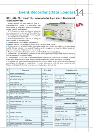
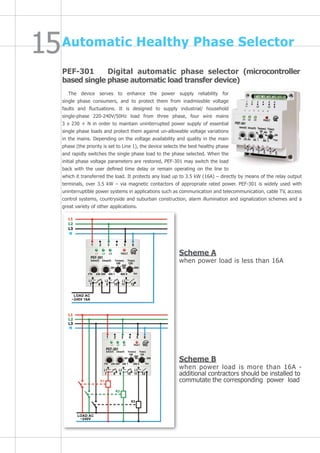
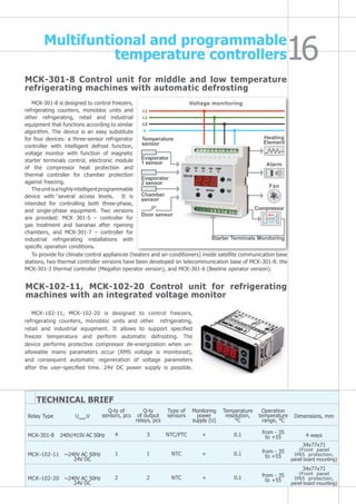


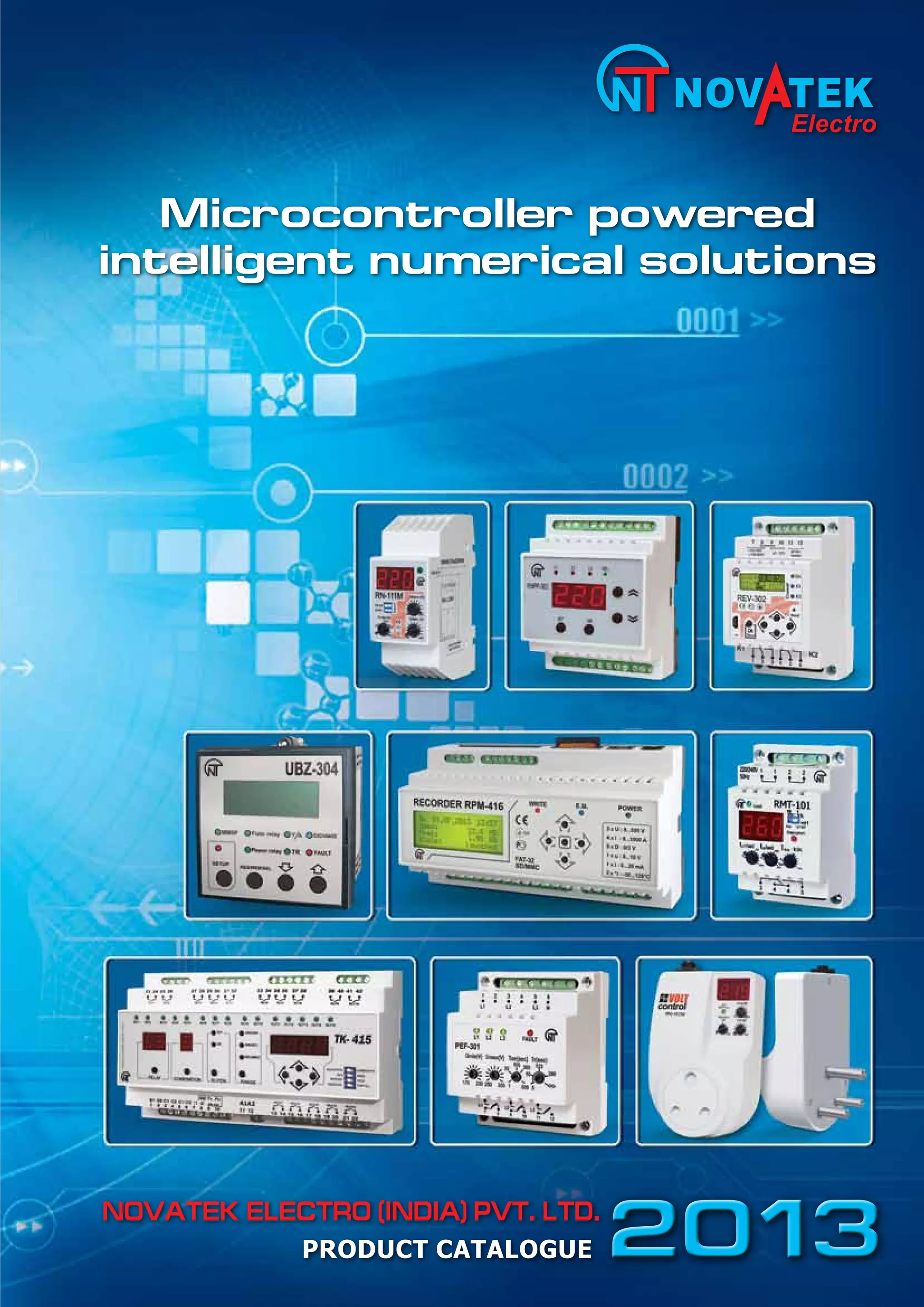
The document is a product catalogue from Novatek Electro that describes several microcontroller-based protection and automation devices. It includes: 1) Introductions of Novatek Electro and its research, design, and manufacturing capabilities for innovative microcontroller devices. 2) Descriptions of several single phase and three phase voltage monitoring relays that protect loads from voltage fluctuations and provide additional functions. 3) Details of timing relays and a multifunctional programmable timer that can automate processes based on time, light, and voltage conditions.