Download to read offline
![Suresh Sagadevan Int. Journal of Engineering Research and Applications www.ijera.com
ISSN : 2248-9622, Vol. 4, Issue 4( Version 9), April 2014, pp.126-130
www.ijera.com 126 | P a g e
AC and DC Electrical Conductivity Measurements on Glycine
Family of Nonlinear Optical (NLO) Single Crystals
Suresh Sagadevan*
*Department of Physics, Sree Sastha Institute of Engineering and Technology, Chembarambakkam, Chennai,
600123
Abstract
In the present work, the AC/DC conductivity studies were carried out on Glycine family of NLO single crystals such
as Trisglycine Zinc Chloride (TGZC), Triglycine Acetate (TGAc) and Glycine Lithium Sulphate (GLS). The AC
conductivity measurements were carried out using HIOKI 3532-50 LCR HITESTER in the frequency range of
50 Hz to 5 MHz for the grown NLO single crystals. The DC electrical conductivity measurements were also carried
out for the crystals using the conventional two – probe technique in the temperature range of 313 – 423 K. The
present study indicates that both the AC and DC conductivity of the samples increase with the increase in
temperature. The activation energies were also calculated from AC/DC conductivity studies.
Keywords AC conductivity, DC conductivity, Glycine family of NLO Single Crystal
I. Introduction
Extensive studies have been made on the
synthesis and crystal growth of nonlinear optical (NLO)
materials over the past decade because of their potential
applications in the field of telecommunications, optical
signal processing and optical switching [1]. Organic
nonlinear optical materials are attracting a great deal of
attention due to their potentially high nonlinearities and
rapid response in the electro-optic effect compared to
inorganic NLO materials. The development of optical
devices such as photonic integrated circuitry depends
strongly on the design of highly efficient NLO
materials. Among such NLO materials, organic
materials are known to be superior to their inorganic
counterparts in terms of synthesis, crystal fabrication,
potential to create large devices and much faster optical
nonlinearities [2, 3]. Operation of electro-optic devices
is based on the Pockel’s effect, in which the change in
the dielectric constant is a linear function of the applied
field [4]. Microelectronics industry needs replacement
of dielectric materials in multilevel interconnect
structures with new low dielectric constant(εr)
materials, as an interlayer dielectric (ILD) which
surrounds and insulates interconnect wiring. Lowering
the dielectric constant values of the ILD decreases the
RC delay, lowers power consumptions, and reduces
‘cross-talk’ between nearby interconnects [5]. The
electrical conduction in dielectrics is mainly a defect
controlled process in the low temperature region. The
presence of impurities and vacancies mainly determine
the behaviour in this region. The energy needs to form
the defect is much larger than the energy needed for its
drift. The conductivity of the crystal in the higher
temperature region is determined by the intrinsic
defects caused due to the thermal fluctuations in the
crystal [6]. The low temperature conduction region
seems to be connected to the mobility of vacancies. If
the probability of occupation of an interstitial is f, then
the probability of finding a vacant neighbour site is
(1–f). Even for very high concentrations, of the order of
1020
cm–3
, f does not exceed 10–2
so that in real cases
with concentration of interstitials of the order of
1015
–1020
cm–3
, (1–f ) » 1[7]. Electrical conductivity
may be influenced by the proton transport within the
framework of hydrogen bonds. The conductivity is
associated with the incorporation of impurity into the
crystal lattice (of impurities) and the formation of
corresponding defects in ionic crystals [8-10]. The
proton conduction may be accounted for the motion of
protons accompanied by a D defect (excess of positive
charge). Migration of these defects may only modify
electric polarization and may not change the charge at
an electrode. In the present investigation, the AC/DC
conductivity studies were carried out on Glycine family
of NLO single crystals such as Trisglycine Zinc
Chloride (TGZC), Triglycine Acetate (TGAc), and
Glycine Lithium Sulphate (GLS). The activation
energies were also calculated from AC/DC conductivity
studies.
II. Materials and Methods
The NLO single crystals were grown by slow
evaporation technique. Growth, Single crystal X-ray
diffraction, UV analysis, FTIR, SHG, Thermal and
Mechanical analysis, and Photoconductivity studies
have been reported earlier by Suresh et al [11-13]. The
RESEARCH ARTICLE OPEN ACCESS](https://image.slidesharecdn.com/w4409126130-140529023204-phpapp01/85/W4409126130-1-320.jpg)
![Suresh Sagadevan Int. Journal of Engineering Research and Applications www.ijera.com
ISSN : 2248-9622, Vol. 4, Issue 4( Version 9), April 2014, pp.126-130
www.ijera.com 127 | P a g e
conductivity of the material depends on its overall
characteristics such as chemical composition, purity
and crystal structure. Measurements taken with
continuous currents provide only total conductivity.
However, simultaneous information on conductivity
and on the material’s electrode interface effects can be
partially offset by impedance measurements.
Impedance measurement is a flexible tool for electrical
characterization of materials. The compacted pellet
(diameter 8 mm) of the sample is dried at 100ºC for few
hours. In the present study, electric ohmic contacts were
made using air drying silver paint on the opposite faces.
Electrical measurements were taken in the frequency
range from 50 Hz to 5 MHz using HIOKI 3532 LCR
HITESTER. The AC impedance measurements were
taken in the thermal range of 313 to 423 K. A chromel-
Alumel thermocouple was employed to record the
sample temperature. A time interval 30 minutes was
taken prior to thermal stabilization after each measuring
temperature. All the measurements were carried out in
atmospheric air.
2.1. AC CONDUCTIVITY STUDY
A capacitor when charged under AC voltage
will have some loss current due to ohmic resistance or
impedance by heat absorption. If Q be the charge in
Coulomb due to a potential difference of V volts
between two plates of a condenser of area, A, and inter-
plate distance d, then AC conductivity (ζac) due to AC
voltage is given by the relation
EJac / (1)
J is the current density and is the electric field strength
vector. But the electric field vector, E
= D
/ε,
where is the displacement field vector of the dipole
charges and ε is the complex permittivity of the
material. For a parallel plate capacitor, the electric field
intensity ( E
) is the ratio of potential difference
between the plates of the capacitor and the inter-plate
distance. i.e.
dVE /
(2)
The current density, where Q is given by
dAVQ /
Therefore,
dtdVddVdtddtdQAJ /./)/(//)/1(
(3)
dtdVdJ /)/( (4)
Substituting for and J in (1)
jEJac
/ (5)
where ε is a complex quantity
''')'''( jjjac (6)
In order that the AC conductivity may be a real
quantity, the term containing j has to be neglected.
Hence,
'' ac (7)
In any dielectric material, there will be power
loss because of the work done to overcome the
frictional damping forces encountered by the dipoles
during their rotation. If AC field is considered, then in
an ideal case the charging current IC will be 90º out of
phase with the voltage. But in most of the capacitors
due to the absorption of electrical energy some loss
current, IL will also be produced, which will be in phase
with the voltage. Charging current, IC, and loss current,
IL, will make angles δ and θ, respectively with the total
current (I), passing through the capacitor. The loss
current is represented by sin δ with respect to the total
current (I). Generally, sin δ is called the loss factor, but
when δ is small then, sin δ = δ = tan δ. But the two
components ε’ and ε’’ of the complex dielectric constant
(ε,) will be frequency dependent and is given by
00 /cos)(' ED
00 /sin)('' ED
(8)
Since the displacement vector in a time varying field
will not be in phase with E
there will be a phase
difference δ between them. From (7) and (8), we have
)('/)(''tan (9)
Substituting the value of (ω) from (6) and (9) we have
)('tan ac (10)
where ω = 2πf and r 0' , where εr is the relative
permittivity of the material and ε0 the permittivity of the
free space. So
rac f 0tan2 (11)
This equation is used to calculate the AC
conductivity using dielectric constant and tan δ at a
given frequency. It is to be noted that both tan δ and εr
were available from dielectric measurement. The plots
between ln(ζac) and 1000/ T were found to be very
linear. Hence, the conductivity values can be fitted to
the relation
]/exp[0 kTEac
(12)
Where is the activation energy, k, the
Boltzmann constant, T, the absolute temperature and ζ0
the parameter depending on the material. Activation
energy was estimated using the slopes of the above line
plots [ E
= -(slope)k x1000].
2.2. DC CONDUCTIVITY STUDY
The DC conductivity of the grown crystals
was measured using the two-probe technique. The
samples (rectangular shaped crystals) were cut parallel](https://image.slidesharecdn.com/w4409126130-140529023204-phpapp01/85/W4409126130-2-320.jpg)
![Suresh Sagadevan Int. Journal of Engineering Research and Applications www.ijera.com
ISSN : 2248-9622, Vol. 4, Issue 4( Version 9), April 2014, pp.126-130
www.ijera.com 130 | P a g e
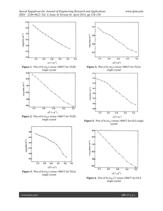
IV. Conclusion
Single crystals of Semi-organic nonlinear
optical materials, such as Trisglycine Zinc Chloride
(TGZC), Triglycine Acetate (TGAc), and Glycine
Lithium Sulphate (GLS) have been grown by slow
evaporation method. The AC/DC electrical conductivity
studies were carried out on the grown single crystals.
The AC electrical conductivity studies were carried out
on the grown single crystals. The activation energy of
TGZC, TGAc and GLS for the conduction process
calculated from plots is found to be 0.035 eV, 0.075 eV
and 0.10 eV. The activation energy for temperatures
range of 313 to 423 K has been calculated from DC
conductivity studies. It is found to be 0.050 eV, 0.060
eV and 0.055 eV for the crystals TGZC, TGAc and
GLS respectively. The lower activation energies
estimated from electrical conductivity studies suggests
that the material contains less number of charge carriers
for conduction process and the dielectric behaviour is
very well understood.
REFERENCES
[1] Prasad PN and Williams DJ, Introduction to
nonlinear optical effects in organic molecules
and polymers. Wiley, NY, (1991)
[2] Jordon G, Kobayashi T, Blau WJ, Pfeiffer S,
Horhold H-H, Advanced Functional Material.
13, (2003), 751–4.
[3] Yang Z, Aravazhi S, Schneider A, Seiler P,
Jazbisnek M, Gunter P. Advanced Functional
Materials. 15, (2005), 1072–6
[4] Boyd GT, J. Opt. Soc. Am. B 6, (1989), 685
[5] Hatton BT, Landskron K, Hunks WJ, Benett
MR, Shukaris D, Perovic DD, and Ozinn GA,
Mater. Today. 9, (2006), 22
[6] Freeda T H and Mahadevan C, Bull. Mater.
Sci., 23, (2000), 335
[7] Bunget I and Popescu M, Physics of dielectrics
(New York: Elsevier) (1984)
[8] Deepa G, Freeda T H and Mahadevan C,
Indian J. Phys., A76, (2002 ), 369
[9] Priya M, Padma C M, Freeda T H, Mahadevan
C and Balasingh C, Bull. Mater. Sci., 24,
(2001), 511
[10] Sancta J A, Sutha A G, Freeda T H, Mahadevan
C and Balasingh C, Indian J. Phys. A75,
(2001), 245
[11] Suresh S and Arivuoli D, Journal of Minerals
& Materials Characterization &
Engineering,6,(2011), 517-526
[12] Suresh S, Ramanand A, Jayaraman D, Mani P
Journal of Optoelectronics and Advanced
materials – rapid communications, 11, (2010)
176
[13] Suresh S, Ramanand A, Jayaraman D, Navis
Priya SM, Journal of Minerals & Materials
Characterization & Engineering, 12, (2010),
1071](https://image.slidesharecdn.com/w4409126130-140529023204-phpapp01/85/W4409126130-5-320.jpg)

The document reports on a study of the AC and DC conductivity of three glycine family nonlinear optical (NLO) single crystals: Trisglycine Zinc Chloride (TGZC), Triglycine Acetate (TGAc), and Glycine Lithium Sulphate (GLS). The AC conductivity was measured from 50 Hz to 5 MHz and increased with temperature for all crystals. The activation energies calculated from the AC conductivity were 0.035 eV for TGZC, 0.075 eV for TGAc, and 0.10 eV for GLS. The DC conductivity also increased with temperature from 313 K to 423 K, and the activation energies calculated were 0.050 eV for TGZC, 0.060 eV