Downloaded 258 times

![Pain associated with
Compression vertebral fractures
• Primary osteoporosis
• steroid-induced osteoporosis
• Neoplastic-induced fracture
• Sub-acute traumatic collapse
• Vertebral angiomas
• Symptomatic microfracture [MRI]
• Lytic lesion [CT] without loss of vertebral height](https://image.slidesharecdn.com/techniques-191123161646/85/Vertebroplasty-and-Kyphoplasty-Techniques-6-320.jpg)
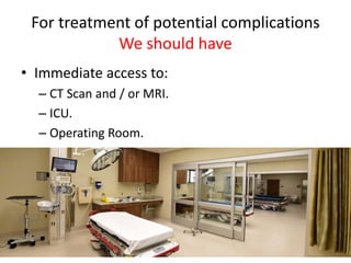

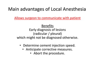
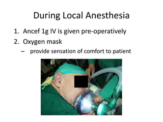
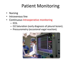
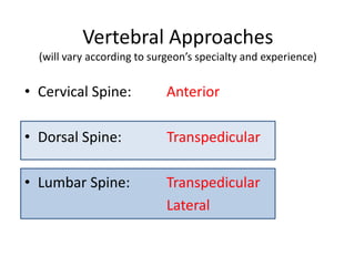
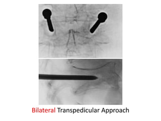
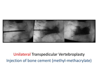
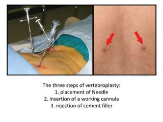

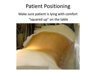
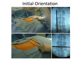
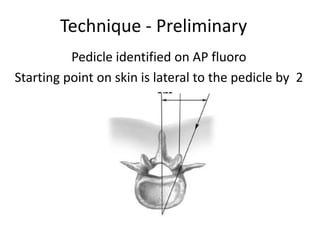
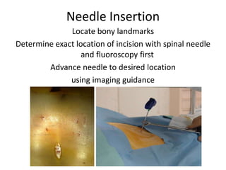
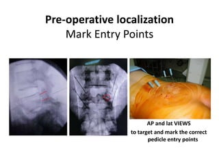
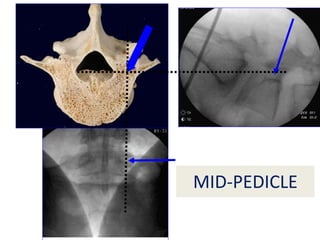
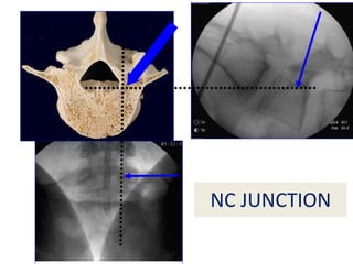
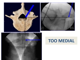
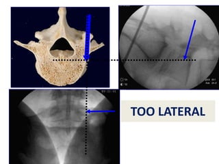

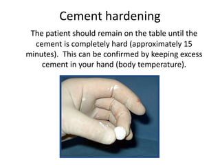

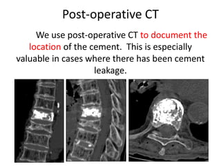

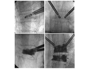
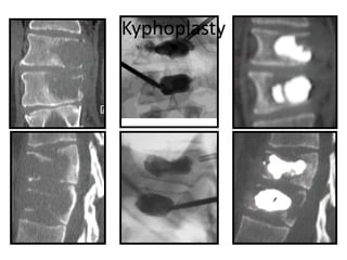
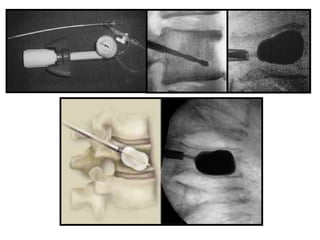

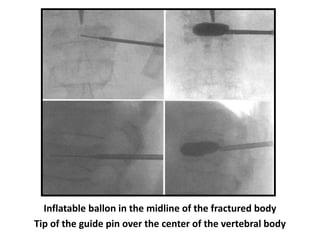
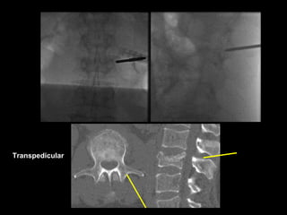
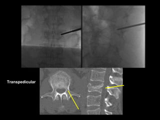
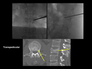
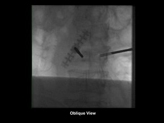
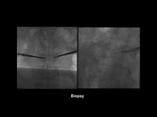
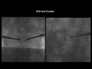
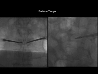
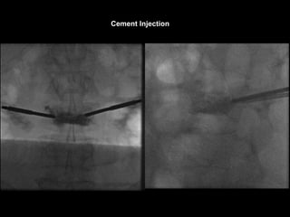
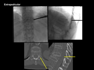
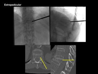
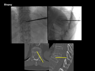


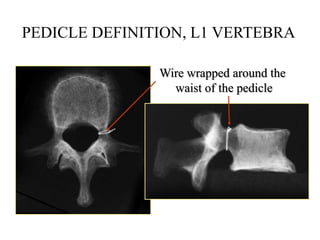
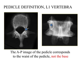
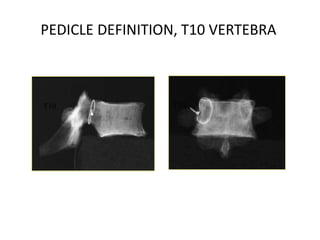
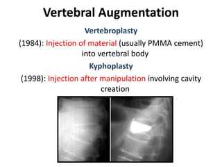
This document discusses vertebroplasty and kyphoplasty techniques. It describes: 1. Vertebroplasty involves injecting bone cement like PMMA into a vertebral body to treat osteoporotic fractures, while kyphoplasty also involves cavity creation before injection. 2. The document outlines the procedure for vertebroplasty, including patient selection, anesthesia, needle placement using fluoroscopy guidance, cement mixing and injection, and monitoring for complications like leakage. 3. Key aspects of the procedure discussed are pedicle definition, approaches like transpedicular, cement properties, and ensuring the needle and cement stay within the vertebral body to avoid issues. Safety and complications are emphasized throughout.


