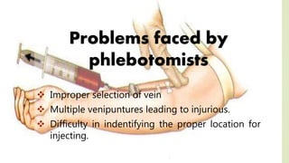
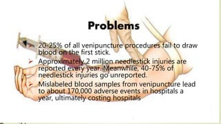
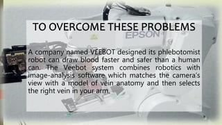
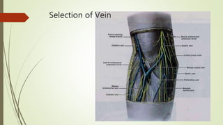
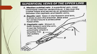
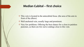
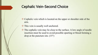
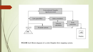
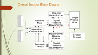
NAME: SYED TEHZEEB ALAM
REG NO:1171110191
BRANCH: EIE
Phlebotomists are people trained to draw blood
from a patient for clinical or medical testing,
transfusions, donations, or research. Phlebotomists
are trained through a certification program; this
program can be online, but it is recommended to be
in a classroom. Phlebotomists collect blood primarily
by performing venipunctures.
Problems faced by
phlebotomists
 Improper selection of vein
 Multiple venipuntures leading to injurious.
 Difficulty in indentifying the proper location for
injecting.
Problems
 20-25% of all venipuncture procedures fail to draw
blood on the first stick.
 Approximately 2 million needlestick injuries are
reported every year. Meanwhile, 40-75% of
needlestick injuries go unreported.
 Mislabeled blood samples from venipuncture lead
to about 170,000 adverse events in hospitals a
year, ultimately costing hospitals
A company named VEEBOT designed its phlebotomist
robot can draw blood faster and safer than a human
can. The Veebot system combines robotics with
image-analysis software which matches the camera’s
view with a model of vein anatomy and then selects
the right vein in your arm.
VEEBOT PHLEBOTOMIST
Their mission is to make the whole procedure of venipuncture automated to
reduce error and decrease venipuncture times. This saves hospitals and
clinics money, reduces the risk of injury to practitioners, and improves
comfort and care for patients.
Veebot LLC was started in 2010 by a team of Stanford engineers and the
president of a contract research organization. Veebot started in Miami, FL
and is now located in Mountain View, CA.
WORKING PRINCIPLE
To use the Veebot system, a patient puts his or her arm through an
archway over a padded table. Inside the archway, an inflatable cuff
tightens around the arm, holding it in place and restricting blood flow to
make the veins easier to see. An infrared light illuminates the inner elbow
for a camera; software matches the camera’s view against a model of
vein anatomy and selects a likely vein. The vein is examined with
ultrasound to confirm that it’s large enough and has sufficient blood
flowing through it. The robot then aligns the needle and sticks it in. The
whole process takes about a minute, and the only thing the technician
has to do is attach the appropriate test tube or IV bag
VEEBOT PHLEBOTOMIST
Flowchart
Place the arm
Infrared detectors
detect the correct
vein
Ultrasonic
Doppler blood
flow
measurement
Veni puncture
Vein Selection
 Choose the veins that are large and accessible.
 Large veins that are not well anchored in tissue
frequently roll, so if you choose one, be sure to secure it
with the thumb of your nondominant hand when you
penetrate it with the needle.
 Avoid bruised and scarred areas.
Selection of Vein
Median Cubital – first choice
 This vein is located in the antecubital fossa. (the area of the arm in
front of the elbow)
 Well anchored vein, usually large and prominent.
 Very few problems. Offering the best chance for a close to painless
puncture, as there are few nerve endings close to this vein.
Cephalic Vein-Second Choice
 Cephalic vein which is located on the upper or shoulder side of the
arm.
 This vein is usually well anchored.
 The cephalic vein may lie close to the surface. A low angle of needle
insertion must be used to avoid possible spurting or blood forming a
drop at the puncture site. (15°)
Basilic Vein-Third Choice
 Located on the under side of the arm.
 In many patients this vein may not be well anchored and will roll,
making it difficult to access with the needle.
 Syringe draw should be considered as it gives the phlebotomist
more control over a rolling vein. Pooling of blood and hematoma
formation possible.
 The basilic vein is close to the brachial artery so there is more risk
of hitting an artery. Exercise caution when drawing from this area.
Additionally, this area is often more sensitive, thus a stick is slightly
more painful for the patient
16
Physical properties of ultrasound
Before we will deal with diagnostic devices, we need to
understand what is ultrasound and what are the main
acoustical properties of medium.
Ultrasound (US) is mechanical oscillations with
frequency above 20 kHz which propagate through an
elastic medium.
In liquids and gases, US propagates as longitudinal
waves.
In solids, US propagates also as transversal waves.
17
Interactions of US with Tissue
 Reflection (smooth homogeneous interfaces of size greater than beam
width, e.g. organ outlines)
 Rayleigh Scatter (small reflector sizes, e.g. blood cells, dominates in
non-homogeneous media)
 Refraction (away from normal from less dense to denser medium, note
opposite to light, sometimes produces distortion)
 Absorption (sound to heat)
 absorption increases with f, note opposite to X-rays
 absorption high in lungs, less in bone, least in soft tissue, again note
opposite to x-rays
 Interference: ‘speckles’ in US image result of interference between
Rayleigh scattered waves
 Diffraction
18 Acoustic parameters of medium:
Interaction of US
with medium –
reflection and
back-scattering,
refraction,
attenuation
(scattering and
absorption)
19
Ultrasonography
A-mode – one-dimensional
Distances between reflecting interfaces and the
probe are shown.
Reflections from individual interfaces (boundaries of
media with different acoustic impedances) are
represented by vertical deflections of base line, i.e. the
echoes.
Echo amplitude is proportional to the intensity of
reflected waves (amplitude modulation)
Distance between echoes shown on the screen is
proportional to real distance between tissue interfaces.
Today used mainly in ophthalmology.
20
Ultrasonography
A-mode – one-dimensional
21
A tomogram is depicted.
Brightness of points on the screen represents intensity of
reflected US waves (brightness modulation).
Static B-scan: a cross-section image of examined area in
the plane given by the beam axis and direction of manual
movement of the probe on body surface. The method
was used in 50‘ and 60‘ of 20th century
Ultrasonography
B-mode – two-dimensional
22
Ultrasonography
B-mode – two-
dimensional - static
23
Ultrasonography M-mode
One-dimensional static B-scan shows movement of reflecting
tissues. The second dimension is time in this method.
Static probe detects reflections from moving structures. The bright
points move vertically on the screen, horizontal shifting of the record
is given by slow time-base.
Displayed curves represent movement of tissue structures
chest wall
lungs
24
Ultrasonography
Comparison of A-, B- and M-mode principle
25
Doppler flow measurement
The Doppler effect (frequency shift of waves
formed or reflected at a moving object) can be
used for detection and measurement of blood
flow, as well as, for detection and measurement
of movements of some acoustical interfaces
inside the body (foetal heart, blood vessel walls)
Christian. A. Doppler (1803-1853), Austrian physicist
and mathematician, formulated his theory in 1842
during his stay in Prague.
26
perceived frequency
corresponds with source
frequency in rest
perceived frequency is higher
when approaching
perceived frequency is lower
when moving away
Doppler flow measurement
Principle of Doppler effect
27
US Doppler blood flow-meters
are based on the difference between the frequency of
ultrasound (US) waves emitted by the probe and those reflected
(back-scattered) by moving erythrocytes.
The frequency of reflected waves is (in comparison with the
emitted waves)
higher in forward blood flow (towards the probe)
lower in back blood flow (away from the probe)
The difference between the frequencies of emitted and reflected
US waves is proportional to blood flow velocity.
Doppler flow measurement
Principle of blood flow measurement
28
Doppler flow measurement
General principle of blood flow measurement
29
1) Systems with continuous wave – CW. They are used for measurement
on superficial blood vessels. High velocities of flow can be measured,
but without depth resolution. Used only occasionally.
2) Systems with pulsed wave. It is possible to measure blood flow with
accurate depth localisation. Measurement of high velocities in depths is
limited.
Doppler flow measurement
The Doppler effect
The Doppler effect describes a phenomenon in which a change in the
frequency of sound emitted from a source is perceived by an observer
when the source or the observer is moving or both are moving.
The difference between the actual frequency of the source, f, and the
perceived frequency, f ′, is called the Doppler frequency.
The Doppler effect is used in ultrasonic Doppler devices for the
measurement and imaging of blood flow transcutaneously, i.e., without
penetrating the skin in any manner. In these devices, ultrasonic waves
are launched into a blood vessel by an ultrasonic transducer and the
scattered radiation from the moving red cells is detected by the same
transducer or a separate transducer.
Transmission principle
• IR laser tomography
Emission principle
IR photography
thermography
liquid crystals
thermovision - b&w
- colour thermovision camera
- digital
IR imaging technique
Planck’s law Wien law
E = k.T4
Physical principles of thermovision
IR detector – semiconductor InSb - cooling by liquid N2 (-196o C)
Technical scheme of thermovision
Clinical aplication
Inflamatory proceses – joints, soft tissues
Phlebology – vein trombosis
Vascular cancer
1
Overall Imager Block Diagram
2
3 4 5
6
Veebot’s Phlebotomist

Veebot’s Phlebotomist

  • 1.
    NAME: SYED TEHZEEBALAM REG NO:1171110191 BRANCH: EIE
  • 2.
    Phlebotomists are peopletrained to draw blood from a patient for clinical or medical testing, transfusions, donations, or research. Phlebotomists are trained through a certification program; this program can be online, but it is recommended to be in a classroom. Phlebotomists collect blood primarily by performing venipunctures.
  • 3.
    Problems faced by phlebotomists Improper selection of vein  Multiple venipuntures leading to injurious.  Difficulty in indentifying the proper location for injecting.
  • 4.
    Problems  20-25% ofall venipuncture procedures fail to draw blood on the first stick.  Approximately 2 million needlestick injuries are reported every year. Meanwhile, 40-75% of needlestick injuries go unreported.  Mislabeled blood samples from venipuncture lead to about 170,000 adverse events in hospitals a year, ultimately costing hospitals
  • 5.
    A company namedVEEBOT designed its phlebotomist robot can draw blood faster and safer than a human can. The Veebot system combines robotics with image-analysis software which matches the camera’s view with a model of vein anatomy and then selects the right vein in your arm.
  • 6.
    VEEBOT PHLEBOTOMIST Their missionis to make the whole procedure of venipuncture automated to reduce error and decrease venipuncture times. This saves hospitals and clinics money, reduces the risk of injury to practitioners, and improves comfort and care for patients. Veebot LLC was started in 2010 by a team of Stanford engineers and the president of a contract research organization. Veebot started in Miami, FL and is now located in Mountain View, CA.
  • 7.
    WORKING PRINCIPLE To usethe Veebot system, a patient puts his or her arm through an archway over a padded table. Inside the archway, an inflatable cuff tightens around the arm, holding it in place and restricting blood flow to make the veins easier to see. An infrared light illuminates the inner elbow for a camera; software matches the camera’s view against a model of vein anatomy and selects a likely vein. The vein is examined with ultrasound to confirm that it’s large enough and has sufficient blood flowing through it. The robot then aligns the needle and sticks it in. The whole process takes about a minute, and the only thing the technician has to do is attach the appropriate test tube or IV bag
  • 8.
    VEEBOT PHLEBOTOMIST Flowchart Place thearm Infrared detectors detect the correct vein Ultrasonic Doppler blood flow measurement Veni puncture
  • 10.
    Vein Selection  Choosethe veins that are large and accessible.  Large veins that are not well anchored in tissue frequently roll, so if you choose one, be sure to secure it with the thumb of your nondominant hand when you penetrate it with the needle.  Avoid bruised and scarred areas.
  • 11.
  • 13.
    Median Cubital –first choice  This vein is located in the antecubital fossa. (the area of the arm in front of the elbow)  Well anchored vein, usually large and prominent.  Very few problems. Offering the best chance for a close to painless puncture, as there are few nerve endings close to this vein.
  • 14.
    Cephalic Vein-Second Choice Cephalic vein which is located on the upper or shoulder side of the arm.  This vein is usually well anchored.  The cephalic vein may lie close to the surface. A low angle of needle insertion must be used to avoid possible spurting or blood forming a drop at the puncture site. (15°)
  • 15.
    Basilic Vein-Third Choice Located on the under side of the arm.  In many patients this vein may not be well anchored and will roll, making it difficult to access with the needle.  Syringe draw should be considered as it gives the phlebotomist more control over a rolling vein. Pooling of blood and hematoma formation possible.  The basilic vein is close to the brachial artery so there is more risk of hitting an artery. Exercise caution when drawing from this area. Additionally, this area is often more sensitive, thus a stick is slightly more painful for the patient
  • 16.
    16 Physical properties ofultrasound Before we will deal with diagnostic devices, we need to understand what is ultrasound and what are the main acoustical properties of medium. Ultrasound (US) is mechanical oscillations with frequency above 20 kHz which propagate through an elastic medium. In liquids and gases, US propagates as longitudinal waves. In solids, US propagates also as transversal waves.
  • 17.
    17 Interactions of USwith Tissue  Reflection (smooth homogeneous interfaces of size greater than beam width, e.g. organ outlines)  Rayleigh Scatter (small reflector sizes, e.g. blood cells, dominates in non-homogeneous media)  Refraction (away from normal from less dense to denser medium, note opposite to light, sometimes produces distortion)  Absorption (sound to heat)  absorption increases with f, note opposite to X-rays  absorption high in lungs, less in bone, least in soft tissue, again note opposite to x-rays  Interference: ‘speckles’ in US image result of interference between Rayleigh scattered waves  Diffraction
  • 18.
    18 Acoustic parametersof medium: Interaction of US with medium – reflection and back-scattering, refraction, attenuation (scattering and absorption)
  • 19.
    19 Ultrasonography A-mode – one-dimensional Distancesbetween reflecting interfaces and the probe are shown. Reflections from individual interfaces (boundaries of media with different acoustic impedances) are represented by vertical deflections of base line, i.e. the echoes. Echo amplitude is proportional to the intensity of reflected waves (amplitude modulation) Distance between echoes shown on the screen is proportional to real distance between tissue interfaces. Today used mainly in ophthalmology.
  • 20.
  • 21.
    21 A tomogram isdepicted. Brightness of points on the screen represents intensity of reflected US waves (brightness modulation). Static B-scan: a cross-section image of examined area in the plane given by the beam axis and direction of manual movement of the probe on body surface. The method was used in 50‘ and 60‘ of 20th century Ultrasonography B-mode – two-dimensional
  • 22.
  • 23.
    23 Ultrasonography M-mode One-dimensional staticB-scan shows movement of reflecting tissues. The second dimension is time in this method. Static probe detects reflections from moving structures. The bright points move vertically on the screen, horizontal shifting of the record is given by slow time-base. Displayed curves represent movement of tissue structures chest wall lungs
  • 24.
    24 Ultrasonography Comparison of A-,B- and M-mode principle
  • 25.
    25 Doppler flow measurement TheDoppler effect (frequency shift of waves formed or reflected at a moving object) can be used for detection and measurement of blood flow, as well as, for detection and measurement of movements of some acoustical interfaces inside the body (foetal heart, blood vessel walls) Christian. A. Doppler (1803-1853), Austrian physicist and mathematician, formulated his theory in 1842 during his stay in Prague.
  • 26.
    26 perceived frequency corresponds withsource frequency in rest perceived frequency is higher when approaching perceived frequency is lower when moving away Doppler flow measurement Principle of Doppler effect
  • 27.
    27 US Doppler bloodflow-meters are based on the difference between the frequency of ultrasound (US) waves emitted by the probe and those reflected (back-scattered) by moving erythrocytes. The frequency of reflected waves is (in comparison with the emitted waves) higher in forward blood flow (towards the probe) lower in back blood flow (away from the probe) The difference between the frequencies of emitted and reflected US waves is proportional to blood flow velocity. Doppler flow measurement Principle of blood flow measurement
  • 28.
    28 Doppler flow measurement Generalprinciple of blood flow measurement
  • 29.
    29 1) Systems withcontinuous wave – CW. They are used for measurement on superficial blood vessels. High velocities of flow can be measured, but without depth resolution. Used only occasionally. 2) Systems with pulsed wave. It is possible to measure blood flow with accurate depth localisation. Measurement of high velocities in depths is limited. Doppler flow measurement
  • 30.
    The Doppler effect TheDoppler effect describes a phenomenon in which a change in the frequency of sound emitted from a source is perceived by an observer when the source or the observer is moving or both are moving. The difference between the actual frequency of the source, f, and the perceived frequency, f ′, is called the Doppler frequency. The Doppler effect is used in ultrasonic Doppler devices for the measurement and imaging of blood flow transcutaneously, i.e., without penetrating the skin in any manner. In these devices, ultrasonic waves are launched into a blood vessel by an ultrasonic transducer and the scattered radiation from the moving red cells is detected by the same transducer or a separate transducer.
  • 31.
    Transmission principle • IRlaser tomography Emission principle IR photography thermography liquid crystals thermovision - b&w - colour thermovision camera - digital IR imaging technique
  • 32.
    Planck’s law Wienlaw E = k.T4 Physical principles of thermovision
  • 33.
    IR detector –semiconductor InSb - cooling by liquid N2 (-196o C) Technical scheme of thermovision
  • 34.
    Clinical aplication Inflamatory proceses– joints, soft tissues Phlebology – vein trombosis Vascular cancer
  • 40.
    1 Overall Imager BlockDiagram 2 3 4 5 6