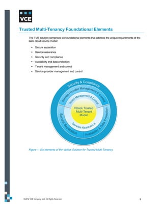
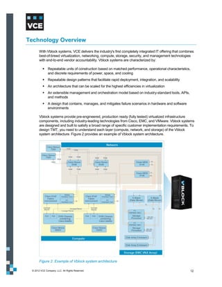
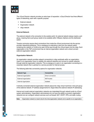
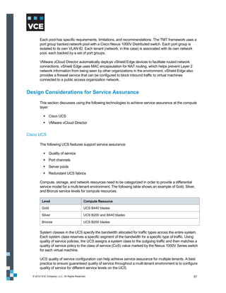
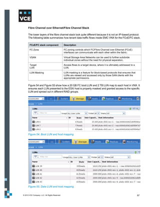
This document provides an overview of the Vblock Solution for Trusted Multi-Tenancy (TMT). It describes the six foundational elements of TMT: secure separation, service assurance, security and compliance, availability and data protection, tenant management and control, and service provider management and control. It then provides technology overviews of the management, compute, storage, network, and security components used in Vblock systems to address each foundational element. The remainder of the document discusses design considerations for each technology area.

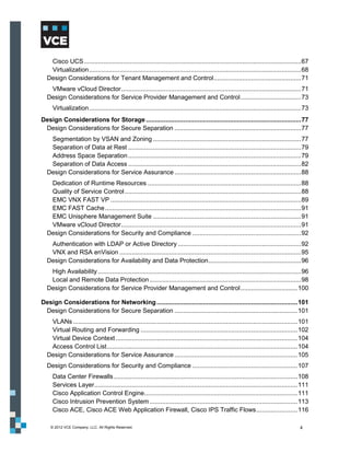
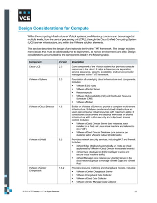
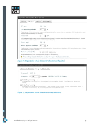


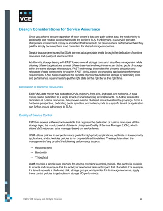
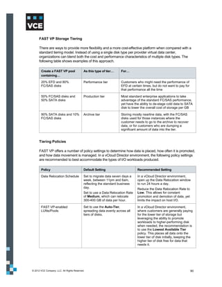
![Figure 56 shows how you can create policies with a specific set of I/O class to ensure that SLAs are
maintained.
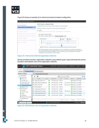
Figure 56. EMC VNX – QoS configuration
EMC VNX FAST VP
With standard storage tiering in a non-FAST VP enabled array, multiple storage tiers are typically
presented to the vCloud environment, and each offering is abstracted out into separate provider virtual
data centers (vDC). A provider may choose to provision an EFD [SSD/Flash] tier, an FC/SAS tier, and
a SATA/NL-SAS tier, and then abstract these into Gold, Silver, and Bronze provider virtual data
centers. The customer then chooses resources from these for use in their organizational virtual data
center.
This provisioning model is limited for a number of reasons, including the following:
VMware vCloud Director does not allow for a non-disruptive way to move virtual machines from
one provider virtual data center to another. This means the customer must provide for downtime
if the vApp needs to be moved to a more appropriate tier.
For workloads with a variable I/O personality, there is no mechanism to automatically migrate
those workloads to a more appropriate disk tier.
With the cost of enterprise flash drives (EFD) still significant, creating an entire tier of them can
be prohibitively expensive, especially with few workloads having an I/O pattern that takes full
advantage of this particular storage medium.
One way in which the standard storage tiering model can be beneficial is when multiple arrays are
used to provide different kinds of storage to support different I/O workloads.
© 2012 VCE Company, LLC. All Rights Reserved. 89](https://image.slidesharecdn.com/tmt-design-guide-121202102031-phpapp01/85/VBLOCK-SOLUTION-FOR-TRUSTED-MULTI-TENANCY-DESIGN-GUIDE-89-320.jpg)