The document summarizes a group project analyzing V-bending of sheet metal using finite element analysis. It includes:
1. Names of the 7 group members and description of their online collaboration methods.
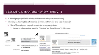
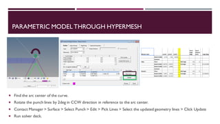
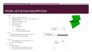
2. An overview of the project which involves modeling V-bending in NX and HyperMesh, running iterations in Abaqus to optimize the design, and comparing solid, shell and continuum shell meshes.
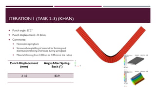
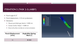
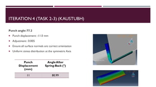
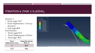
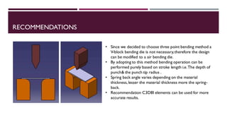
3. Details of the 8 iterations run by group members, with the punch angle and displacement varying to achieve a 90° bend after springback. The best results were obtained with a punch angle of 73.2° and displacement of 9.75mm.