Download to read offline
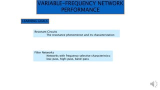
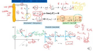
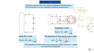
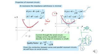
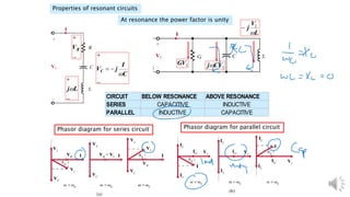
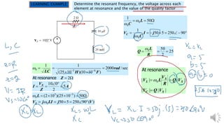
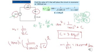
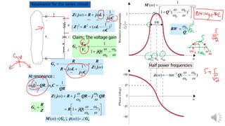
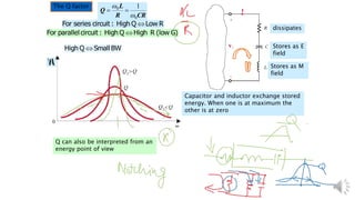
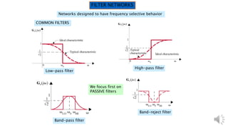
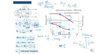
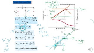
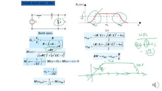
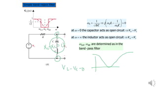
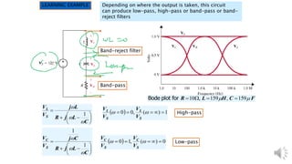

This document discusses resonant circuits and filter networks. It begins by defining resonant circuits and their properties like resonant frequency and quality factor. It then discusses different types of passive filter networks, including low-pass, high-pass, band-pass and band-reject filters. Simple circuit examples are given for each type of filter to demonstrate their frequency response characteristics. The document also provides learning examples to illustrate how to analyze resonant circuits and determine the behavior of filter networks based on where the output is taken.


