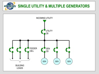
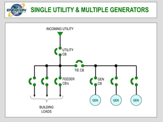
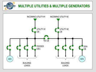
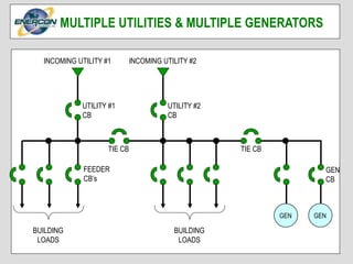
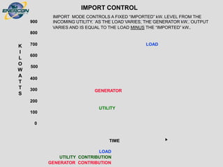
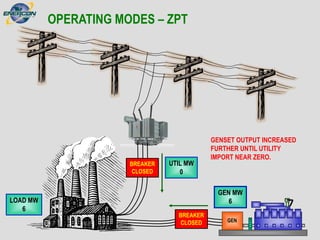
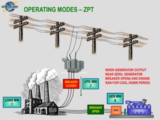
UTILITY & GENERATOR
PARALLELING SYSTEMS
BY
Rev3 3/10
System Configurations
 Single & Multiple Generators
 Single & Multiple Utilities
Generator & Utility Protection and Utility Approval
Momentary Paralleling vs. Soft Load/Unload
Operating Modes
 Base Load Control
 Import / Export Control
 Zero Power Transfer (ZPT) or Storm Anticipation
Utility and Generator (Plant) Islanding
Power Factor Control
GEN
INCOMING UTILITY
FEEDER
CB’s
GEN
CB
BUILDING
LOADS
UTILITY
CB
SINGLE UTILITY & SINGLE GENERATOR
INCOMING UTILITY
GEN
UTILITY
CB
BUILDING
LOADS
GEN
CB
GEN GEN
FEEDER
CB’s
SINGLE UTILITY & MULTIPLE GENERATORS
INCOMING UTILITY
GEN GENGEN
GEN
CB
BUILDING
LOADS
TIE CB
UTILITY
CB
FEEDER
CB’s
SINGLE UTILITY & MULTIPLE GENERATORS
INCOMING UTILITY #2
GEN
BUILDING
LOADS
INCOMING UTILITY #1
BUILDING
LOADS
FEEDER
CB’s
TIE CB
UTILITY #2
CB
UTILITY #1
CB
GEN
CB
MULTIPLE UTILITIES & SINGLE GENERATOR
INCOMING UTILITY #2
GEN
BUILDING
LOADS
INCOMING UTILITY #1
BUILDING
LOADS
FEEDER
CB’s
TIE CB
UTILITY #2
CB
UTILITY #1
CB
GEN
GEN
CB
MULTIPLE UTILITIES & MULTIPLE GENERATORS
INCOMING UTILITY #2
GEN
BUILDING
LOADS
INCOMING UTILITY #1
BUILDING
LOADS
GEN
FEEDER
CB’s
UTILITY #2
CB
TIE CB
UTILITY #1
CB
GEN
CB
MULTIPLE UTILITIES & MULTIPLE GENERATORS
INCOMING UTILITY #2
GEN
BUILDING
LOADS
INCOMING UTILITY #1
BUILDING
LOADS
GEN
FEEDER
CB’s
UTILITY #2
CB
TIE CB TIE CB
UTILITY #1
CB
GEN
CB
MULTIPLE UTILITIES & MULTIPLE GENERATORS
INCOMING UTILITY #2
BUILDING
LOADS
BUILDING
LOADS
GENGEN
FEEDER
CB’s
UTILITY #1
CB
TIE CB TIE CBTIE CB
FEEDER
CB’s
UTILITY #2
CB
GEN
CB
INCOMING UTILITY #1
MULTIPLE UTILITIES & MULTIPLE GENERATORS
 27 – Under voltage
 32 – Reverse power
 32RV – Reverse VARS (loss of excitation)
 46 – Negative phase sequence overcurrent (phase
unbalance or single phasing)
 50/51 – Instantaneous / time overcurrent
 51V – Time overcurrent with voltage restraint
 51G – Ground overcurrent
 59 – Over voltage
 81O/U – Over / under frequency
 86 – Lock out
 87G – Generator differential overcurrent
GENERATOR PROTECTION
GEN
52
CT
CTs
(3)
CTs
(3)
CTs
(3)
27
87G
46
51G
81
O/U
59
86
32
RV
32
50/
51
GENERATOR PROTECTION
PTs
TO 86
FROM 87G
52 TRIP SIGNAL
27 – Under voltage
32 – Reverse power
47 – Phase sequence / under voltage
50/51 – Instantaneous / time overcurrent
51G – Ground overcurrent
51N – Zero sequence overcurrent
59 – Over voltage
59G – Ground overvoltage
81O/U – Over / under frequency
86 – Lock out
87T – Transformer differential overcurrent
UTILITY PROTECTION
52
CT
CTs
(3)
27/
59
51G
81
O/U
47
86
32
50/
51
INCOMING UTILITY
FROM HIGHLINE
PTs
FROM 87T
52 TRIP SIGNAL
51N
UTILITY PROTECTION
CTs
(3)
CTs
(3)
87T
TO 86
TO SITE LOAD NETOWRK
UTILITY APPROVAL FOR PARALLELING
Utility Requirements
 Interconnect agreement forms/documents.
 One-line of proposed system.
 Utility protective relaying chosen, utility usually gives their
requirements or choice of mfg.
 Preliminary relay settings.
 DC schematics showing tripping schemes.
 Utility may require transfer trip.
 Some utilities may require full protection even for
momentary paralleling.
Generator Protection
 Not normally approved by utility.
 Typically specified by consulting eng.
Extended parallel time
More components required
Generally more relaying
protection required
Extends breaker contact life
with normal operation
Little or no power surges
between utility and
generator
Generally less than 100 milli-sec.
Fewer components
Sometimes less relaying
requirements
More wear on breaker contacts
More power surges to utility and
generator
SOFT LOAD/UNLOADMOMENTARY PARALLELING
Extended parallel time
More components required
Generally more relaying
protection required
Extends breaker contact life
with normal operation
Little or no power surges
between utility and
generator
Generally less than 100 milli-sec.
Fewer components
Sometimes less relaying
requirements
More wear on breaker contacts
More power surges to utility and
generator
MOMENTARY vs SOFT LOAD/UNLOAD
Generator Kw output controlled by biasing Governor
 Analog
 Digital
 Communications
Generator PF controlled by biasing voltage regulator.
 Analog
 Digital
 Communications
GENERATOR LOAD CONTROL
UTILITY PARALLELING MODES OF OPERATION
Base Load
 Constant generator kW output
Import Control
 Constant kW input from utility
Export Control (rarely used mode)
 Constant kW utility sell back to utility
Zero Power Transfer
 Control rate of power flow (transfer) to/from utility/generator
Genset produces constant kW output regardless of
utility or load levels.
Used for generation at landfills.
If not contracted by utility, load should always be
greater than generator output or excess kW will be
“back fed” into utility grid.
Gas turbines operate well with base loading since some
or most are used with heat recovery.
BASE LOADING
LOAD
UTILITY CONTRIBUTION
GENERATOR CONTRIBUTION
-100
0
100
200
300
400
500
600
700
800
900
K
I
L
O
W
A
T
T
S
TIME
BASE LOAD
BASE LOAD CONTROLS A FIXED GENERATOR kW.. OUTPUT LEVEL. IF
THE LOAD IS GREATER THAN THE GENERATOR OUTPUT, POWER IS
“IMPORTED” FROM THE UTILITY. IF THE LOAD IS LESS THAN THE
GENERATOR OUTPUT, POWER IS “EXPORTED” TO THE UTILITY.
LOAD
GENERATOR
UTILITY
OPERATING MODES – BASE LOAD
UTIL MW
8
LOAD MW
8
GEN MW
0
GEN
BREAKER
OPEN
BREAKER
CLOSED
BASE LOAD MODE INITIATED –
GENSET STARTED
OPERATING MODES – BASE LOAD
UTIL MW
8
LOAD MW
8
GEN MW
0
GEN
BREAKER
CLOSED
BREAKER
CLOSED
GENSET PARALLELED TO
UTILIITY – BASE LOAD SET
POINT = 6 MW.
OPERATING MODES – BASE LOAD
UTIL MW
7
LOAD MW
8
GEN MW
1
GEN
BREAKER
CLOSED
BREAKER
CLOSED
GENSET LOADING STARTED –
BASE LOAD SET POINT = 6 MW.
OPERATING MODES – BASE LOAD
UTIL MW
2
LOAD MW
8
GEN MW
6
GEN
BREAKER
CLOSED
BREAKER
CLOSED
GENSET OUTPUT AT BASE
LOAD SET POINT OF 6 MW.
OPERATING MODES – BASE LOAD
UTIL MW
-1
LOAD MW
5
GEN MW
6
GEN
BREAKER
CLOSED
BREAKER
CLOSED
LOAD DECREASES, GENSET
OUTPUT GREATER THAN LOAD,
EXCESS EXPORTED TO UTILITY
GRID.
OPERATING MODES – BASE LOAD
UTIL MW
3
LOAD MW
5
GEN MW
2
GEN
BREAKER
CLOSED
BREAKER
CLOSED
BASE LOAD TERMINATED,
GENSET UNLOADS
OPERATING MODES – BASE LOAD
UTIL MW
5
LOAD MW
5
GEN MW
0
GEN
BREAKER
OPEN
BREAKER
CLOSED
GENSET OUTPUT NEAR ZERO,
BREAKER OPENS, ENGINE RAN
FOR COOL DOWN PERIOD.
Also referred to as peak shaving or load following.
Used for utility load curtailment contracts.
Load dependant start/stop can be used with multiple
genset installations.
Export control not very commonly used.
IMPORT / EXPORT CONTROL
0
100
200
300
400
500
600
700
800
900
K
I
L
O
W
A
T
T
S
TIME
LOAD
UTILITY CONTRIBUTION
GENERATOR CONTRIBUTION
IMPORT CONTROL
IMPORT MODE CONTROLS A FIXED “IMPORTED” kW. LEVEL FROM THE
INCOMING UTILITY. AS THE LOAD VARIES, THE GENERATOR kW.. OUTPUT
VARIES AND IS EQUAL TO THE LOAD MINUS THE “IMPORTED” kW..
LOAD
GENERATOR
UTILITY
0
-100
200
300
400
500
600
700
800
900
K
I
L
O
W
A
T
T
S
TIME
LOAD
UTILITY CONTRIBUTION
GENERATOR CONTRIBUTION
EXPORT CONTROL
EXPORT MODE CONTROLS A FIXED “EXPORTED” kW. LEVEL TO THE
INCOMING UTILITY. AS THE LOAD VARIES, THE GENERATOR kW.. OUTPUT
VARIES AND IS EQUAL TO THE LOAD PLUS THE “EXPORTED” kW..
LOAD
GENERATOR
UTILITY
100
OPERATING MODES – IMPORT
UTIL MW
8
LOAD MW
8
GEN MW
0
GEN
BREAKER
OPEN
BREAKER
CLOSED
IMPORT MODE INITIATED –
GENSET STARTED
OPERATING MODES – IMPORT
UTIL MW
8
LOAD MW
8
GEN MW
0
GEN
BREAKER
CLOSED
BREAKER
CLOSED
GENSET PARALLELED TO
UTILIITY – IMPORT SET POINT =
1 MW.
OPERATING MODES – IMPORT
UTIL MW
7
LOAD MW
8
GEN MW
1
GEN
BREAKER
CLOSED
BREAKER
CLOSED
GENSET OUTPUT INCREASED,
UTILITY IMPORT DECREASES.
OPERATING MODES – IMPORT
UTIL MW
1
LOAD MW
8
GEN MW
7
GEN
BREAKER
CLOSED
BREAKER
CLOSED
GENSET OUTPUT INCREASED
UNTIL UTILITY IMPORT SET
POINT IS MET (I MW).
OPERATING MODES – IMPORT
UTIL MW
2
LOAD MW
9
GEN MW
7
GEN
BREAKER
CLOSED
BREAKER
CLOSED
LOAD INCREASES, UTILITY
IMPORT SET POINT NOT MET.
OPERATING MODES – IMPORT
UTIL MW
1
LOAD MW
9
GEN MW
8
GEN
BREAKER
CLOSED
BREAKER
CLOSED
GENSET OUTPUT FURTHER
INCRESED UNTIL UTILITY
IMPORT SET POINT MET.
OPERATING MODES – IMPORT
UTIL MW
-2
LOAD MW
6
GEN MW
8
GEN
BREAKER
CLOSED
BREAKER
CLOSED
LOAD DECREASES, GENSET
OUTPUT “BACK-FED” TO
UTILITY.
OPERATING MODES – IMPORT
UTIL MW
1
LOAD MW
6
GEN MW
5
GEN
BREAKER
CLOSED
BREAKER
CLOSED
GENSET OUTPUT DECRESED
UNTIL UTILITY IMPORT SET
POINT MET.
OPERATING MODES – IMPORT
UTIL MW
2
LOAD MW
6
GEN MW
4
GEN
BREAKER
CLOSED
BREAKER
CLOSED
IMPORT MODE TERMINATED,
GENSET OUTPUT DECRESED.
OPERATING MODES – IMPORT
UTIL MW
6
LOAD MW
6
GEN MW
0
GEN
BREAKER
OPEN
BREAKER
CLOSED
GENSET OUTPUT NEAR ZERO,
BREAKER OPENS AND ENGINE
RAN FOR COOL DOWN PERIOD.
Soft transfer of load to and from generator and utility.
Common mode of operation used at Data Centers or
other critical load networks.
Sometimes referred to as “storm anticipation” or
“storm avoidance”.
ZERO POWER TRANSFER
GENERATOR CONTRIBUTION
LOAD
UTILITY
TIME
0
A B C D
100
200
300
400
500
600
700
800
900
1000
K
I
L
O
W
A
T
T
S
ZERO POWER TRANSFER
A. THE GENERATOR BREAKER CLOSES AND THE GENERATOR STARTS TO LOAD
WHICH REDUCES THE UTILITY kW..
B. THE UTILITY kW.. IS REDUCED TO ZERO AND UTILITY BREAKER OPENS. SITE
POWERED BY GENERATOR.
C. AFTER THE GENERATOR IS RE-SYNCHRONIZED TO THE UTILITY, UTILITY
BREAKER IS CLOSED AND THE GENERATOR UNLOADING IS STARTED.
D. THE GENERATOR kW.. IS REDUCED TO ZERO AND GENERATOR BREAKER
OPENS. SITE NOW POWERED BY UTILITY.
LOAD
GENERATOR
UTILITY
UTILITY
GENERATOR
OPERATING MODES – ZPT
UTIL MW
6
LOAD MW
6
GEN MW
0
GEN
BREAKER
OPEN
BREAKER
CLOSED
ZPT MODE INITIATED – GENSET
STARTED
OPERATING MODES – ZPT
UTIL MW
6
LOAD MW
6
GEN MW
0
GEN
BREAKER
CLOSED
BREAKER
CLOSED
GENSET PARALLELED TO
UTILITY
OPERATING MODES – ZPT
UTIL MW
5
LOAD MW
6
GEN MW
1
GEN
BREAKER
CLOSED
BREAKER
CLOSED
GENSET OUTPUT INCREASED
OPERATING MODES – ZPT
UTIL MW
0
LOAD MW
6
GEN MW
6
GEN
BREAKER
CLOSED
BREAKER
CLOSED
GENSET OUTPUT INCREASED
FURTHER UNTIL UTILITY
IMPORT NEAR ZERO.
OPERATING MODES – ZPT
UTIL MW
0
LOAD MW
6
GEN MW
6
GEN
BREAKER
CLOSED
BREAKER
OPEN
WHEN UTILITY IMPORT NEAR
ZERO, UTILITY BREAKER
OPENS.
OPERATING MODES – ZPT
UTIL MW
0
LOAD MW
7
GEN MW
7
GEN
BREAKER
CLOSED
BREAKER
OPEN
GENSET SUPPLIES POWER TO
FACILITY DURING ZPT DURATION
OPERATING MODES – ZPT
UTIL MW
0
LOAD MW
7
GEN MW
7
GEN
BREAKER
CLOSED
BREAKER
OPEN
ZPT TERMINATED, GENSET
PARALLELED TO UTILITY.
OPERATING MODES – ZPT
UTIL MW
0
LOAD MW
7
GEN MW
7
GEN
BREAKER
CLOSED
BREAKER
CLOSED
UTILITY BREAKER CLOSES.
OPERATING MODES – ZPT
UTIL MW
6
LOAD MW
7
GEN MW
1
GEN
BREAKER
CLOSED
BREAKER
CLOSED
GENSET OUTPUT DECREASED
OPERATING MODES – ZPT
UTIL MW
7
LOAD MW
7
GEN MW
0
GEN
BREAKER
CLOSED
BREAKER
CLOSED
GENSET OUTPUT DECREASED
TO NEAR ZERO.
OPERATING MODES – ZPT
UTIL MW
7
LOAD MW
7
GEN MW
0
GEN
BREAKER
OPEN
BREAKER
CLOSED
WHEN GENERATOR OUTPUT
NEAR ZERO, GENERATOR
BREAKER OPENS AND ENGINE
RAN FOR COOL DOWN PERIOD.
Utility “islanding” is a condition that occurs when the utility
source becomes un-available and the site generation is still
connected to the utilities “high line” or network.
Usually caused by a re-closure opening due to a fault, lightning,
downed lines, etc.
Protective relaying is used to detect this condition and opens or
trips the main incoming utility circuit breaker to the facility.
With proper logic and control, the design is such that the
generator system will go into emergency or standby mode
automatically after the utility breaker is tripped by the protective
relays.
UTILITY ISLANDING
ISLANDING PROTECTION
FACTORY #3FACTORY #2
FAULT CAUSES
RECLOSER TO OPEN
BREAKER
CLOSED
ISLANDING PROTECTION
FACTORY #3FACTORY #2
RECLOSER WILL
THEN RE-CLOSE AFTER
TIME DELAY. GEN MUST
BE ISOLATED BY OPENING
PLANT UTILITY BREAKER
BEFORE RECLOSER
CLOSES.
BREAKER
OPEN
ISLANDING PROTECTION
FACTORY #3FACTORY #2
BREAKER
CLOSED
IF UTILITY LINE IS ISLANDED, GENERATOR
OVERLOAD COULD OCCUR WHICH CAUSES
GENERATOR UNDER FREQUENCY AND OR
OVER/UNDER VOLTAGE.
RECLOSER POSITION
NOT MONITORED AT
PLANT.
ISLANDING PROTECTION
FACTORY #3FACTORY #2
PROTECTIVE RELAYING DETECT
ABNORMAL FREQUENCY AND OR VOLTAGE
CONDITION AND OPENS PLANT UTILITY
BREAKER BEFORE RECLOSER CLOSES
BREAKER
OPEN
RECLOSER POSITION
NOT MONITORED AT
PLANT
ISLANDING PROTECTION
BREAKER
CLOSED
IF UTILITY LINE IS ISLANDED, GENERATOR
UNDER LOAD COULD OCCUR WHICH CAUSES
GENERATOR OVER FREQUENCY AND OR
UNDER/OVER VOLTAGE.
RECLOSER POSITION
NOT MONITORED AT
PLANT
ISLANDING PROTECTION
BREAKER
OPEN
RECLOSER POSITION
NOT MONITORED AT
PLANT
PROTECTIVE RELAYING DETECT
ABNORMAL FREQUENCY AND OR VOLTAGE
CONDITION AND OPENS PLANT UTILITY
BREAKER BEFORE RECLOSER CLOSES
If generator voltage is higher than utility voltage, the generator is
referred to as being overexcited. Excessive vars are generated
which can result in generator power factor being lower than the
0.8 PF. lagging rating thus overloading the generator.
If generator voltage is lower than utility voltage, the generator is
referred to as being underexcited. Vars are consumed which can
result in generator power factor being leading thus causing
excessive heating in the windings of the generator. Can cause
shutdown from reverse vars relay.
POWER FACTOR CONTROL
Monitors phase angle between current and voltage and changes
excitation to maintain preset PF. (phase angle).
Utility voltage usually not regulated at sites.
Generator set voltage regulators typically regulate output 0.25
to 0.5% accuracy.
Power factor control required anytime generator is paralleled to
utility.
POWER FACTOR CONTROL cont…
WITHOUT GENERATION
Kw kVARS kVA pF.
LOAD CONSUMTION: 1000 750 1250 0.8
UTILITY CONTRIBUTION: 1000 750 1250 0.8
GENERATION WITHOUT PROPER PF CONTROLLER ADJUSTMENT
Kw kVARS kVA pF.
LOAD CONSUMTION: 1000 750 1250 0.8
UTILITY CONTRIBUTION: 500 525 725 0.69
GEN. CONTRIBUTION: 500 225 548 0.91 -- PF. SET
GENERATION WITH PROPER PF CONTROLLER ADJUSTMENT
Kw kVARS kVA pF.
LOAD CONSUMTION: 1000 750 1250 0.8
UTILITY CONTRIBUTION: 500 375 625 0.8
GEN. CONTRIBUTION: 500 375 625 0.8 -- PF. SET
POWER FACTOR CONTROL cont…
UTILITY & GENERATOR
PARALLELING SYSTEMS

Utility & Generator Paralleling System

  • 1.
    UTILITY & GENERATOR PARALLELINGSYSTEMS BY Rev3 3/10
  • 2.
    System Configurations  Single& Multiple Generators  Single & Multiple Utilities Generator & Utility Protection and Utility Approval Momentary Paralleling vs. Soft Load/Unload Operating Modes  Base Load Control  Import / Export Control  Zero Power Transfer (ZPT) or Storm Anticipation Utility and Generator (Plant) Islanding Power Factor Control
  • 3.
  • 4.
  • 5.
    INCOMING UTILITY GEN GENGEN GEN CB BUILDING LOADS TIECB UTILITY CB FEEDER CB’s SINGLE UTILITY & MULTIPLE GENERATORS
  • 6.
    INCOMING UTILITY #2 GEN BUILDING LOADS INCOMINGUTILITY #1 BUILDING LOADS FEEDER CB’s TIE CB UTILITY #2 CB UTILITY #1 CB GEN CB MULTIPLE UTILITIES & SINGLE GENERATOR
  • 7.
    INCOMING UTILITY #2 GEN BUILDING LOADS INCOMINGUTILITY #1 BUILDING LOADS FEEDER CB’s TIE CB UTILITY #2 CB UTILITY #1 CB GEN GEN CB MULTIPLE UTILITIES & MULTIPLE GENERATORS
  • 8.
    INCOMING UTILITY #2 GEN BUILDING LOADS INCOMINGUTILITY #1 BUILDING LOADS GEN FEEDER CB’s UTILITY #2 CB TIE CB UTILITY #1 CB GEN CB MULTIPLE UTILITIES & MULTIPLE GENERATORS
  • 9.
    INCOMING UTILITY #2 GEN BUILDING LOADS INCOMINGUTILITY #1 BUILDING LOADS GEN FEEDER CB’s UTILITY #2 CB TIE CB TIE CB UTILITY #1 CB GEN CB MULTIPLE UTILITIES & MULTIPLE GENERATORS
  • 10.
    INCOMING UTILITY #2 BUILDING LOADS BUILDING LOADS GENGEN FEEDER CB’s UTILITY#1 CB TIE CB TIE CBTIE CB FEEDER CB’s UTILITY #2 CB GEN CB INCOMING UTILITY #1 MULTIPLE UTILITIES & MULTIPLE GENERATORS
  • 11.
     27 –Under voltage  32 – Reverse power  32RV – Reverse VARS (loss of excitation)  46 – Negative phase sequence overcurrent (phase unbalance or single phasing)  50/51 – Instantaneous / time overcurrent  51V – Time overcurrent with voltage restraint  51G – Ground overcurrent  59 – Over voltage  81O/U – Over / under frequency  86 – Lock out  87G – Generator differential overcurrent GENERATOR PROTECTION
  • 12.
  • 13.
    27 – Undervoltage 32 – Reverse power 47 – Phase sequence / under voltage 50/51 – Instantaneous / time overcurrent 51G – Ground overcurrent 51N – Zero sequence overcurrent 59 – Over voltage 59G – Ground overvoltage 81O/U – Over / under frequency 86 – Lock out 87T – Transformer differential overcurrent UTILITY PROTECTION
  • 14.
    52 CT CTs (3) 27/ 59 51G 81 O/U 47 86 32 50/ 51 INCOMING UTILITY FROM HIGHLINE PTs FROM87T 52 TRIP SIGNAL 51N UTILITY PROTECTION CTs (3) CTs (3) 87T TO 86 TO SITE LOAD NETOWRK
  • 15.
    UTILITY APPROVAL FORPARALLELING Utility Requirements  Interconnect agreement forms/documents.  One-line of proposed system.  Utility protective relaying chosen, utility usually gives their requirements or choice of mfg.  Preliminary relay settings.  DC schematics showing tripping schemes.  Utility may require transfer trip.  Some utilities may require full protection even for momentary paralleling. Generator Protection  Not normally approved by utility.  Typically specified by consulting eng.
  • 16.
    Extended parallel time Morecomponents required Generally more relaying protection required Extends breaker contact life with normal operation Little or no power surges between utility and generator Generally less than 100 milli-sec. Fewer components Sometimes less relaying requirements More wear on breaker contacts More power surges to utility and generator SOFT LOAD/UNLOADMOMENTARY PARALLELING Extended parallel time More components required Generally more relaying protection required Extends breaker contact life with normal operation Little or no power surges between utility and generator Generally less than 100 milli-sec. Fewer components Sometimes less relaying requirements More wear on breaker contacts More power surges to utility and generator MOMENTARY vs SOFT LOAD/UNLOAD
  • 17.
    Generator Kw outputcontrolled by biasing Governor  Analog  Digital  Communications Generator PF controlled by biasing voltage regulator.  Analog  Digital  Communications GENERATOR LOAD CONTROL
  • 18.
    UTILITY PARALLELING MODESOF OPERATION Base Load  Constant generator kW output Import Control  Constant kW input from utility Export Control (rarely used mode)  Constant kW utility sell back to utility Zero Power Transfer  Control rate of power flow (transfer) to/from utility/generator
  • 19.
    Genset produces constantkW output regardless of utility or load levels. Used for generation at landfills. If not contracted by utility, load should always be greater than generator output or excess kW will be “back fed” into utility grid. Gas turbines operate well with base loading since some or most are used with heat recovery. BASE LOADING
  • 20.
    LOAD UTILITY CONTRIBUTION GENERATOR CONTRIBUTION -100 0 100 200 300 400 500 600 700 800 900 K I L O W A T T S TIME BASELOAD BASE LOAD CONTROLS A FIXED GENERATOR kW.. OUTPUT LEVEL. IF THE LOAD IS GREATER THAN THE GENERATOR OUTPUT, POWER IS “IMPORTED” FROM THE UTILITY. IF THE LOAD IS LESS THAN THE GENERATOR OUTPUT, POWER IS “EXPORTED” TO THE UTILITY. LOAD GENERATOR UTILITY
  • 21.
    OPERATING MODES –BASE LOAD UTIL MW 8 LOAD MW 8 GEN MW 0 GEN BREAKER OPEN BREAKER CLOSED BASE LOAD MODE INITIATED – GENSET STARTED
  • 22.
    OPERATING MODES –BASE LOAD UTIL MW 8 LOAD MW 8 GEN MW 0 GEN BREAKER CLOSED BREAKER CLOSED GENSET PARALLELED TO UTILIITY – BASE LOAD SET POINT = 6 MW.
  • 23.
    OPERATING MODES –BASE LOAD UTIL MW 7 LOAD MW 8 GEN MW 1 GEN BREAKER CLOSED BREAKER CLOSED GENSET LOADING STARTED – BASE LOAD SET POINT = 6 MW.
  • 24.
    OPERATING MODES –BASE LOAD UTIL MW 2 LOAD MW 8 GEN MW 6 GEN BREAKER CLOSED BREAKER CLOSED GENSET OUTPUT AT BASE LOAD SET POINT OF 6 MW.
  • 25.
    OPERATING MODES –BASE LOAD UTIL MW -1 LOAD MW 5 GEN MW 6 GEN BREAKER CLOSED BREAKER CLOSED LOAD DECREASES, GENSET OUTPUT GREATER THAN LOAD, EXCESS EXPORTED TO UTILITY GRID.
  • 26.
    OPERATING MODES –BASE LOAD UTIL MW 3 LOAD MW 5 GEN MW 2 GEN BREAKER CLOSED BREAKER CLOSED BASE LOAD TERMINATED, GENSET UNLOADS
  • 27.
    OPERATING MODES –BASE LOAD UTIL MW 5 LOAD MW 5 GEN MW 0 GEN BREAKER OPEN BREAKER CLOSED GENSET OUTPUT NEAR ZERO, BREAKER OPENS, ENGINE RAN FOR COOL DOWN PERIOD.
  • 28.
    Also referred toas peak shaving or load following. Used for utility load curtailment contracts. Load dependant start/stop can be used with multiple genset installations. Export control not very commonly used. IMPORT / EXPORT CONTROL
  • 29.
    0 100 200 300 400 500 600 700 800 900 K I L O W A T T S TIME LOAD UTILITY CONTRIBUTION GENERATOR CONTRIBUTION IMPORTCONTROL IMPORT MODE CONTROLS A FIXED “IMPORTED” kW. LEVEL FROM THE INCOMING UTILITY. AS THE LOAD VARIES, THE GENERATOR kW.. OUTPUT VARIES AND IS EQUAL TO THE LOAD MINUS THE “IMPORTED” kW.. LOAD GENERATOR UTILITY
  • 30.
    0 -100 200 300 400 500 600 700 800 900 K I L O W A T T S TIME LOAD UTILITY CONTRIBUTION GENERATOR CONTRIBUTION EXPORTCONTROL EXPORT MODE CONTROLS A FIXED “EXPORTED” kW. LEVEL TO THE INCOMING UTILITY. AS THE LOAD VARIES, THE GENERATOR kW.. OUTPUT VARIES AND IS EQUAL TO THE LOAD PLUS THE “EXPORTED” kW.. LOAD GENERATOR UTILITY 100
  • 31.
    OPERATING MODES –IMPORT UTIL MW 8 LOAD MW 8 GEN MW 0 GEN BREAKER OPEN BREAKER CLOSED IMPORT MODE INITIATED – GENSET STARTED
  • 32.
    OPERATING MODES –IMPORT UTIL MW 8 LOAD MW 8 GEN MW 0 GEN BREAKER CLOSED BREAKER CLOSED GENSET PARALLELED TO UTILIITY – IMPORT SET POINT = 1 MW.
  • 33.
    OPERATING MODES –IMPORT UTIL MW 7 LOAD MW 8 GEN MW 1 GEN BREAKER CLOSED BREAKER CLOSED GENSET OUTPUT INCREASED, UTILITY IMPORT DECREASES.
  • 34.
    OPERATING MODES –IMPORT UTIL MW 1 LOAD MW 8 GEN MW 7 GEN BREAKER CLOSED BREAKER CLOSED GENSET OUTPUT INCREASED UNTIL UTILITY IMPORT SET POINT IS MET (I MW).
  • 35.
    OPERATING MODES –IMPORT UTIL MW 2 LOAD MW 9 GEN MW 7 GEN BREAKER CLOSED BREAKER CLOSED LOAD INCREASES, UTILITY IMPORT SET POINT NOT MET.
  • 36.
    OPERATING MODES –IMPORT UTIL MW 1 LOAD MW 9 GEN MW 8 GEN BREAKER CLOSED BREAKER CLOSED GENSET OUTPUT FURTHER INCRESED UNTIL UTILITY IMPORT SET POINT MET.
  • 37.
    OPERATING MODES –IMPORT UTIL MW -2 LOAD MW 6 GEN MW 8 GEN BREAKER CLOSED BREAKER CLOSED LOAD DECREASES, GENSET OUTPUT “BACK-FED” TO UTILITY.
  • 38.
    OPERATING MODES –IMPORT UTIL MW 1 LOAD MW 6 GEN MW 5 GEN BREAKER CLOSED BREAKER CLOSED GENSET OUTPUT DECRESED UNTIL UTILITY IMPORT SET POINT MET.
  • 39.
    OPERATING MODES –IMPORT UTIL MW 2 LOAD MW 6 GEN MW 4 GEN BREAKER CLOSED BREAKER CLOSED IMPORT MODE TERMINATED, GENSET OUTPUT DECRESED.
  • 40.
    OPERATING MODES –IMPORT UTIL MW 6 LOAD MW 6 GEN MW 0 GEN BREAKER OPEN BREAKER CLOSED GENSET OUTPUT NEAR ZERO, BREAKER OPENS AND ENGINE RAN FOR COOL DOWN PERIOD.
  • 41.
    Soft transfer ofload to and from generator and utility. Common mode of operation used at Data Centers or other critical load networks. Sometimes referred to as “storm anticipation” or “storm avoidance”. ZERO POWER TRANSFER
  • 42.
    GENERATOR CONTRIBUTION LOAD UTILITY TIME 0 A BC D 100 200 300 400 500 600 700 800 900 1000 K I L O W A T T S ZERO POWER TRANSFER A. THE GENERATOR BREAKER CLOSES AND THE GENERATOR STARTS TO LOAD WHICH REDUCES THE UTILITY kW.. B. THE UTILITY kW.. IS REDUCED TO ZERO AND UTILITY BREAKER OPENS. SITE POWERED BY GENERATOR. C. AFTER THE GENERATOR IS RE-SYNCHRONIZED TO THE UTILITY, UTILITY BREAKER IS CLOSED AND THE GENERATOR UNLOADING IS STARTED. D. THE GENERATOR kW.. IS REDUCED TO ZERO AND GENERATOR BREAKER OPENS. SITE NOW POWERED BY UTILITY. LOAD GENERATOR UTILITY UTILITY GENERATOR
  • 43.
    OPERATING MODES –ZPT UTIL MW 6 LOAD MW 6 GEN MW 0 GEN BREAKER OPEN BREAKER CLOSED ZPT MODE INITIATED – GENSET STARTED
  • 44.
    OPERATING MODES –ZPT UTIL MW 6 LOAD MW 6 GEN MW 0 GEN BREAKER CLOSED BREAKER CLOSED GENSET PARALLELED TO UTILITY
  • 45.
    OPERATING MODES –ZPT UTIL MW 5 LOAD MW 6 GEN MW 1 GEN BREAKER CLOSED BREAKER CLOSED GENSET OUTPUT INCREASED
  • 46.
    OPERATING MODES –ZPT UTIL MW 0 LOAD MW 6 GEN MW 6 GEN BREAKER CLOSED BREAKER CLOSED GENSET OUTPUT INCREASED FURTHER UNTIL UTILITY IMPORT NEAR ZERO.
  • 47.
    OPERATING MODES –ZPT UTIL MW 0 LOAD MW 6 GEN MW 6 GEN BREAKER CLOSED BREAKER OPEN WHEN UTILITY IMPORT NEAR ZERO, UTILITY BREAKER OPENS.
  • 48.
    OPERATING MODES –ZPT UTIL MW 0 LOAD MW 7 GEN MW 7 GEN BREAKER CLOSED BREAKER OPEN GENSET SUPPLIES POWER TO FACILITY DURING ZPT DURATION
  • 49.
    OPERATING MODES –ZPT UTIL MW 0 LOAD MW 7 GEN MW 7 GEN BREAKER CLOSED BREAKER OPEN ZPT TERMINATED, GENSET PARALLELED TO UTILITY.
  • 50.
    OPERATING MODES –ZPT UTIL MW 0 LOAD MW 7 GEN MW 7 GEN BREAKER CLOSED BREAKER CLOSED UTILITY BREAKER CLOSES.
  • 51.
    OPERATING MODES –ZPT UTIL MW 6 LOAD MW 7 GEN MW 1 GEN BREAKER CLOSED BREAKER CLOSED GENSET OUTPUT DECREASED
  • 52.
    OPERATING MODES –ZPT UTIL MW 7 LOAD MW 7 GEN MW 0 GEN BREAKER CLOSED BREAKER CLOSED GENSET OUTPUT DECREASED TO NEAR ZERO.
  • 53.
    OPERATING MODES –ZPT UTIL MW 7 LOAD MW 7 GEN MW 0 GEN BREAKER OPEN BREAKER CLOSED WHEN GENERATOR OUTPUT NEAR ZERO, GENERATOR BREAKER OPENS AND ENGINE RAN FOR COOL DOWN PERIOD.
  • 54.
    Utility “islanding” isa condition that occurs when the utility source becomes un-available and the site generation is still connected to the utilities “high line” or network. Usually caused by a re-closure opening due to a fault, lightning, downed lines, etc. Protective relaying is used to detect this condition and opens or trips the main incoming utility circuit breaker to the facility. With proper logic and control, the design is such that the generator system will go into emergency or standby mode automatically after the utility breaker is tripped by the protective relays. UTILITY ISLANDING
  • 55.
    ISLANDING PROTECTION FACTORY #3FACTORY#2 FAULT CAUSES RECLOSER TO OPEN BREAKER CLOSED
  • 56.
    ISLANDING PROTECTION FACTORY #3FACTORY#2 RECLOSER WILL THEN RE-CLOSE AFTER TIME DELAY. GEN MUST BE ISOLATED BY OPENING PLANT UTILITY BREAKER BEFORE RECLOSER CLOSES. BREAKER OPEN
  • 57.
    ISLANDING PROTECTION FACTORY #3FACTORY#2 BREAKER CLOSED IF UTILITY LINE IS ISLANDED, GENERATOR OVERLOAD COULD OCCUR WHICH CAUSES GENERATOR UNDER FREQUENCY AND OR OVER/UNDER VOLTAGE. RECLOSER POSITION NOT MONITORED AT PLANT.
  • 58.
    ISLANDING PROTECTION FACTORY #3FACTORY#2 PROTECTIVE RELAYING DETECT ABNORMAL FREQUENCY AND OR VOLTAGE CONDITION AND OPENS PLANT UTILITY BREAKER BEFORE RECLOSER CLOSES BREAKER OPEN RECLOSER POSITION NOT MONITORED AT PLANT
  • 59.
    ISLANDING PROTECTION BREAKER CLOSED IF UTILITYLINE IS ISLANDED, GENERATOR UNDER LOAD COULD OCCUR WHICH CAUSES GENERATOR OVER FREQUENCY AND OR UNDER/OVER VOLTAGE. RECLOSER POSITION NOT MONITORED AT PLANT
  • 60.
    ISLANDING PROTECTION BREAKER OPEN RECLOSER POSITION NOTMONITORED AT PLANT PROTECTIVE RELAYING DETECT ABNORMAL FREQUENCY AND OR VOLTAGE CONDITION AND OPENS PLANT UTILITY BREAKER BEFORE RECLOSER CLOSES
  • 61.
    If generator voltageis higher than utility voltage, the generator is referred to as being overexcited. Excessive vars are generated which can result in generator power factor being lower than the 0.8 PF. lagging rating thus overloading the generator. If generator voltage is lower than utility voltage, the generator is referred to as being underexcited. Vars are consumed which can result in generator power factor being leading thus causing excessive heating in the windings of the generator. Can cause shutdown from reverse vars relay. POWER FACTOR CONTROL
  • 62.
    Monitors phase anglebetween current and voltage and changes excitation to maintain preset PF. (phase angle). Utility voltage usually not regulated at sites. Generator set voltage regulators typically regulate output 0.25 to 0.5% accuracy. Power factor control required anytime generator is paralleled to utility. POWER FACTOR CONTROL cont…
  • 63.
    WITHOUT GENERATION Kw kVARSkVA pF. LOAD CONSUMTION: 1000 750 1250 0.8 UTILITY CONTRIBUTION: 1000 750 1250 0.8 GENERATION WITHOUT PROPER PF CONTROLLER ADJUSTMENT Kw kVARS kVA pF. LOAD CONSUMTION: 1000 750 1250 0.8 UTILITY CONTRIBUTION: 500 525 725 0.69 GEN. CONTRIBUTION: 500 225 548 0.91 -- PF. SET GENERATION WITH PROPER PF CONTROLLER ADJUSTMENT Kw kVARS kVA pF. LOAD CONSUMTION: 1000 750 1250 0.8 UTILITY CONTRIBUTION: 500 375 625 0.8 GEN. CONTRIBUTION: 500 375 625 0.8 -- PF. SET POWER FACTOR CONTROL cont…
  • 64.