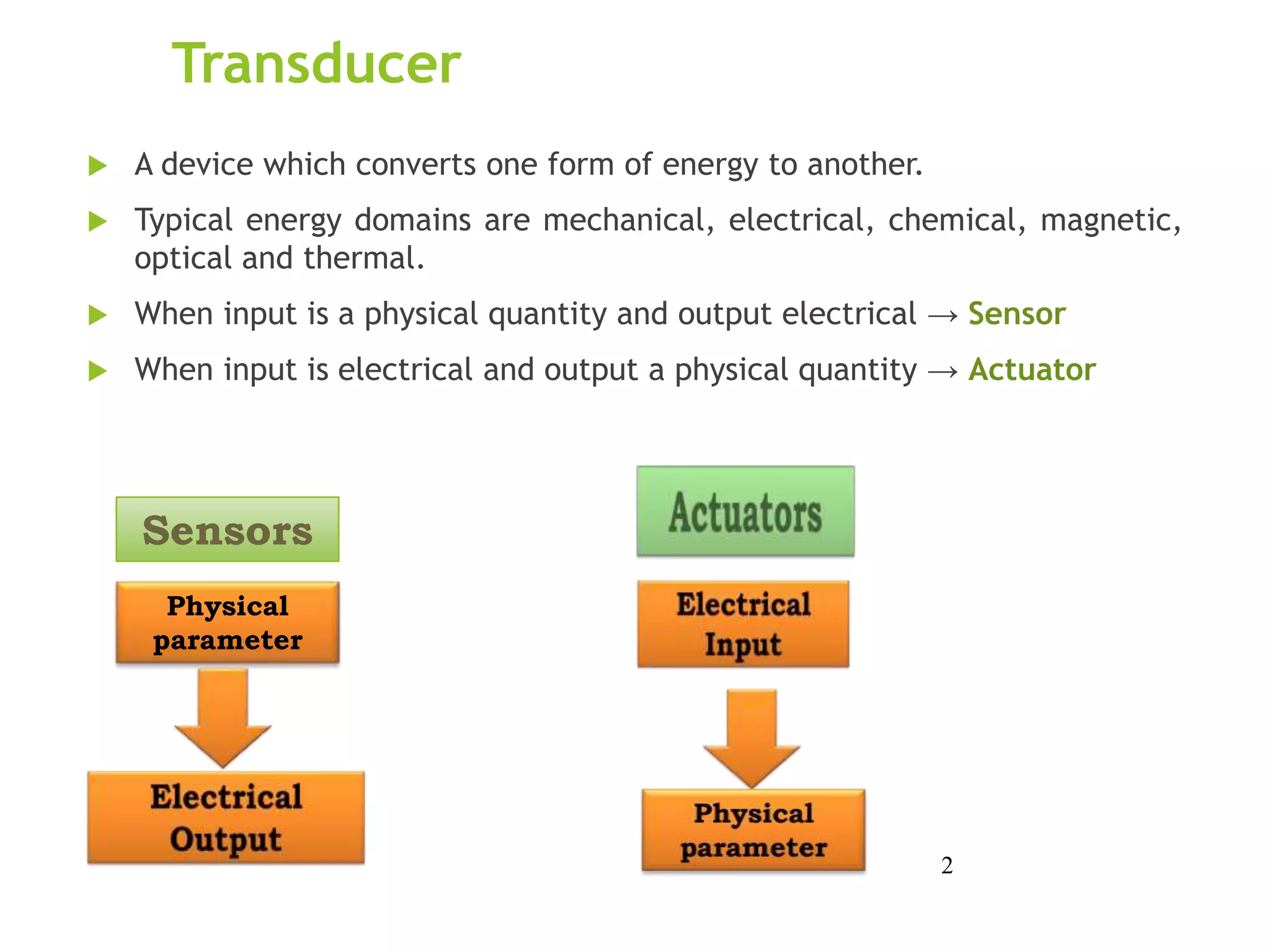
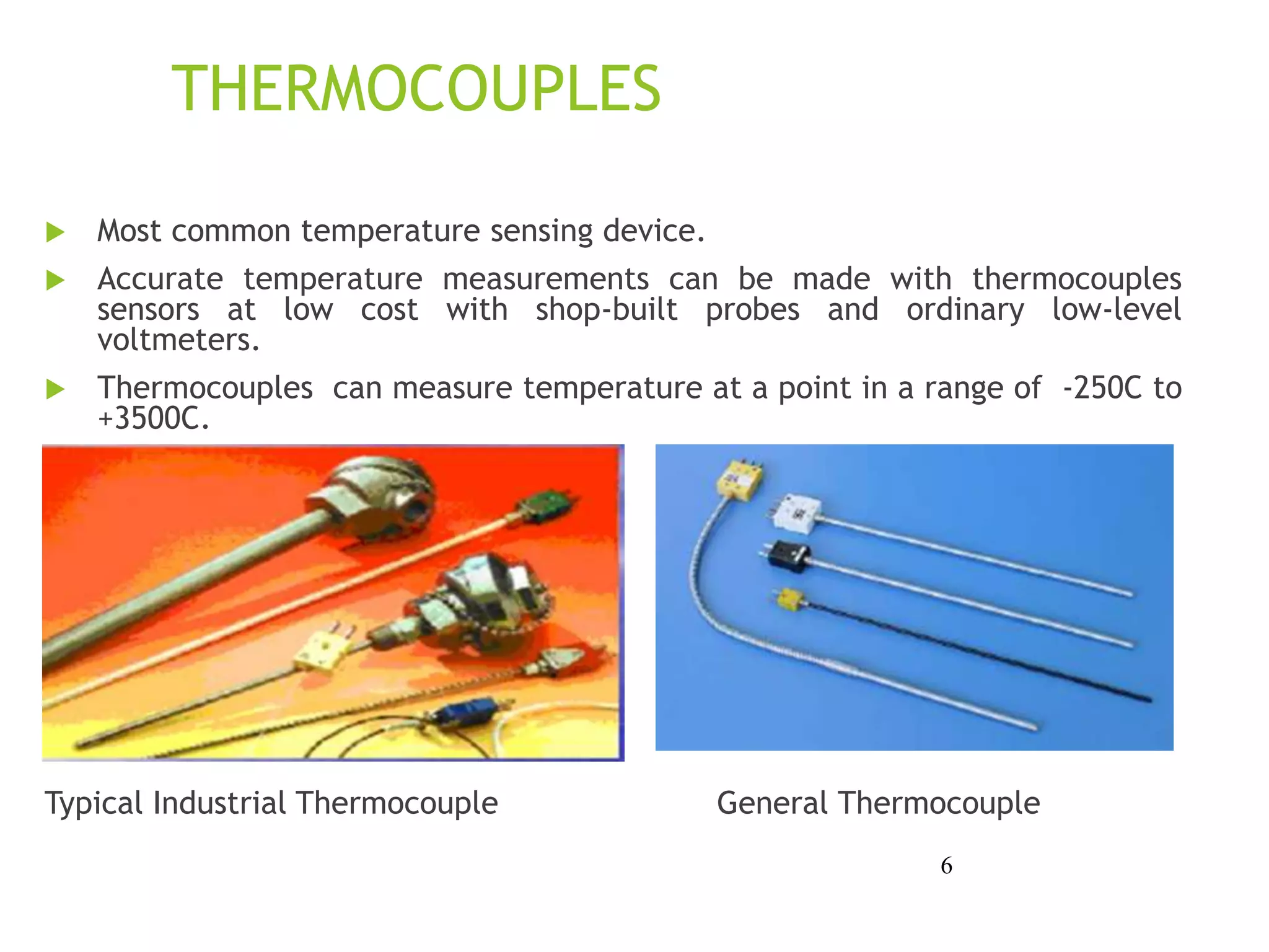
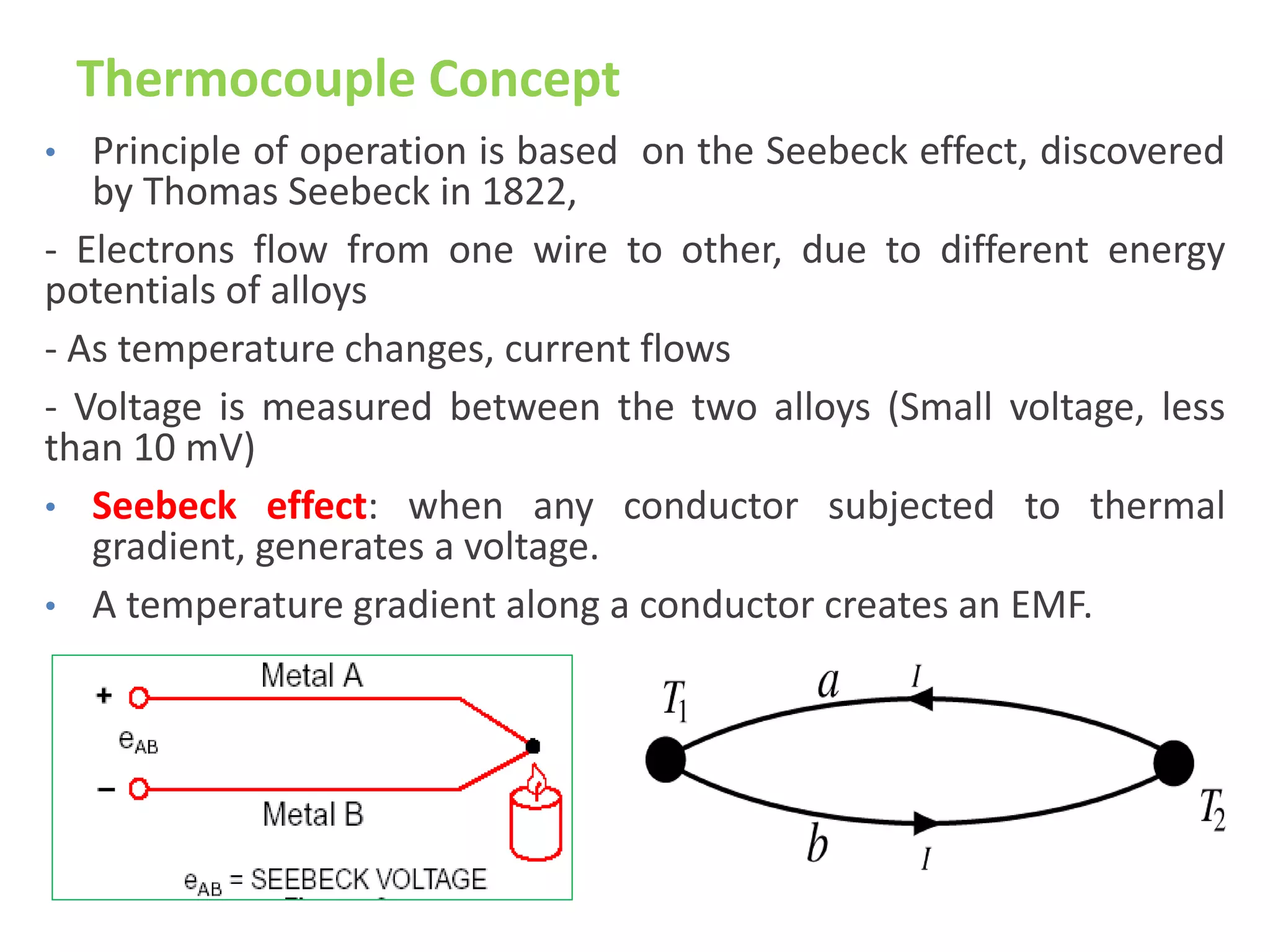
UNIT 4
Transducers
1
Transducer
 A device which converts one form of energy to another.
 Typical energy domains are mechanical, electrical, chemical, magnetic,
optical and thermal.
 When input is a physical quantity and output electrical → Sensor
 When input is electrical and output a physical quantity → Actuator
2
Sensors
Physical
parameter
3
TEMPERATURE SENSORS
Temperature is a scalar quantity that determines the direction of
heat flow between two bodies.
Sensing methods: contact and non-contact
Contact Sensor: is in direct physical contact with the object to
be sensed to monitor solids, liquids, gases over wide range
Non-contact : Interprets the radiant energy of a heat source to
energy in electromagnetic spectrum
Monitor non-reflective solids and liquids
Temperature sensors generate output signals in one of two ways:
1. through a change in output voltage
2. through a change in resistance of the sensor‘s electrical circuit
4
TEMPERATURE SENSORS CLASSIFCATION:
Contact Sensing
 Thermocouple (Thermoelectric)
 Thermistor (Thermal Resistors)
- Negative temperature coefficient device (NTC)
- Positive temperature coefficient device (PTC)
5
THERMOCOUPLES
 Most common temperature sensing device.
 Accurate temperature measurements can be made with thermocouples
sensors at low cost with shop-built probes and ordinary low-level
voltmeters.
 Thermocouples can measure temperature at a point in a range of -250C to
+3500C.

Typical Industrial Thermocouple General Thermocouple
6
Thermocouple Concept
• Principle of operation is based on the Seebeck effect, discovered
by Thomas Seebeck in 1822,
- Electrons flow from one wire to other, due to different energy
potentials of alloys
- As temperature changes, current flows
- Voltage is measured between the two alloys (Small voltage, less
than 10 mV)
• Seebeck effect: when any conductor subjected to thermal
gradient, generates a voltage.
• A temperature gradient along a conductor creates an EMF.
Thermocouple Concept……
• If two conductors of different materials are joined at one
point, an EMF is created between the open ends which is
dependent upon the temperature of the junction.
• As T1 increases, so does Voltage (V).
• EMF also depends on the temperature of the open ends T2.
• The junction is placed in the process, the other end is in
iced water at 0C. This is called the reference junction.
Thermistors: THERMAL RESISTORS
• Thermistor is a combination of the words thermal and resistor.
• Thermistor was invented by Samuel Ruben in 1930
• A thermistor is a type of resistor used to measure temperature
changes, relying on the change in its resistance with changing
temperature.
– Typically have a negative temperature coefficient (NTC),
– Resistance decreases with increasing temperature
• Thermistor can measures across the range of -40~150 ±0.35 °C
Leads, coated Glass encased Surface mount
Relationship b/w resistance & temperature
• Assume a simple linear relationship between resistance
and temperature for the following discussion:
ΔR = k ΔT
Where
• ΔR = change in resistance
• ΔT = change in temperature
• k = first-order temperature coefficient of resistance
Mechanical Sensing - Microswitch
Optical Sensing
• LED’s and Photodiodes
• Transmissive/Reflective
• Modulated/Unmodulated
• Light-on/Dark-on
• Fiber optic
• Solar cell
Transmissive & Reflective Sensors
Beam Pattern and Reflectance
Modulation
• “Chop” LED on and off at many kHz rate
• Bandpass filter after photodiode at the same
frequency as chopping
• Threshold circuit after BPF generates on/off
output
Magnetic Position Sensors
• Reed switches (sense permanent magnet)
• Inductive proximity sensors (eddy current)
• Hall Sensors (sense permanent magnet)
Inductive Proximity Sensor
Solar cells
Solar cells converts light energy into electrical energy. They’re mainly used
for generating solar energy and are made of single-crystal silicon PN
junctions, similar photodiodes but with a broader response curve.
• Unlike photodiodes connected in a reverse-bias configuration, solar cells
are connected in a forward-bias configuration much like typical diodes.
These cells are designed to be sensitive to sunlight instead of a narrow
range of the electromagnetic spectrum. When exposed to solar
radiation, a cell generates a potential difference of 0.58V.
• Typically, several solar cells are connected in series in a panel to output
a greater voltage. This DC voltage can drive a resistive load or be
converted to AC for transmission.
Capacitive Transducers
 capacitive transducers can be
made to be self-contained units.
 Some transducers work by
making one of the capacitor
plates movable, either in such a
way as to vary the overlapping
area or the distance between the
plates.
 Other transducers work by
moving a dielectric material in
and out between two fixed
plates to detect and transmit the
physical position of mechanical
parts via electrical signals
)
( farads
d
kA
C o


where,
k = dielectric constant.
A = Area of the plate
o = 8.854x10⁻¹², in farad per meter.
d= the plate spacing in meters.
Differential Capacitive Transducers
 have 3 wire connections: one wire for each of the "end" plates
and one for the "common" plate.
 implementation in a bridge circuit
Differential Capacitive Transducers
 This bridge circuit is similar in function with strain gauges: it is
not intended to be in a "balanced" condition all the time, but
rather the degree of imbalance represents the magnitude of the
quantity being measured.
THANK YOU
22

UNIT4_IN.ppt

  • 1.
  • 2.
    Transducer  A devicewhich converts one form of energy to another.  Typical energy domains are mechanical, electrical, chemical, magnetic, optical and thermal.  When input is a physical quantity and output electrical → Sensor  When input is electrical and output a physical quantity → Actuator 2 Sensors Physical parameter
  • 3.
  • 4.
    TEMPERATURE SENSORS Temperature isa scalar quantity that determines the direction of heat flow between two bodies. Sensing methods: contact and non-contact Contact Sensor: is in direct physical contact with the object to be sensed to monitor solids, liquids, gases over wide range Non-contact : Interprets the radiant energy of a heat source to energy in electromagnetic spectrum Monitor non-reflective solids and liquids Temperature sensors generate output signals in one of two ways: 1. through a change in output voltage 2. through a change in resistance of the sensor‘s electrical circuit 4
  • 5.
    TEMPERATURE SENSORS CLASSIFCATION: ContactSensing  Thermocouple (Thermoelectric)  Thermistor (Thermal Resistors) - Negative temperature coefficient device (NTC) - Positive temperature coefficient device (PTC) 5
  • 6.
    THERMOCOUPLES  Most commontemperature sensing device.  Accurate temperature measurements can be made with thermocouples sensors at low cost with shop-built probes and ordinary low-level voltmeters.  Thermocouples can measure temperature at a point in a range of -250C to +3500C.  Typical Industrial Thermocouple General Thermocouple 6
  • 7.
    Thermocouple Concept • Principleof operation is based on the Seebeck effect, discovered by Thomas Seebeck in 1822, - Electrons flow from one wire to other, due to different energy potentials of alloys - As temperature changes, current flows - Voltage is measured between the two alloys (Small voltage, less than 10 mV) • Seebeck effect: when any conductor subjected to thermal gradient, generates a voltage. • A temperature gradient along a conductor creates an EMF.
  • 8.
    Thermocouple Concept…… • Iftwo conductors of different materials are joined at one point, an EMF is created between the open ends which is dependent upon the temperature of the junction. • As T1 increases, so does Voltage (V). • EMF also depends on the temperature of the open ends T2. • The junction is placed in the process, the other end is in iced water at 0C. This is called the reference junction.
  • 9.
    Thermistors: THERMAL RESISTORS •Thermistor is a combination of the words thermal and resistor. • Thermistor was invented by Samuel Ruben in 1930 • A thermistor is a type of resistor used to measure temperature changes, relying on the change in its resistance with changing temperature. – Typically have a negative temperature coefficient (NTC), – Resistance decreases with increasing temperature • Thermistor can measures across the range of -40~150 ±0.35 °C Leads, coated Glass encased Surface mount
  • 10.
    Relationship b/w resistance& temperature • Assume a simple linear relationship between resistance and temperature for the following discussion: ΔR = k ΔT Where • ΔR = change in resistance • ΔT = change in temperature • k = first-order temperature coefficient of resistance
  • 11.
  • 12.
    Optical Sensing • LED’sand Photodiodes • Transmissive/Reflective • Modulated/Unmodulated • Light-on/Dark-on • Fiber optic • Solar cell
  • 13.
  • 14.
    Beam Pattern andReflectance
  • 15.
    Modulation • “Chop” LEDon and off at many kHz rate • Bandpass filter after photodiode at the same frequency as chopping • Threshold circuit after BPF generates on/off output
  • 16.
    Magnetic Position Sensors •Reed switches (sense permanent magnet) • Inductive proximity sensors (eddy current) • Hall Sensors (sense permanent magnet)
  • 17.
  • 18.
    Solar cells Solar cellsconverts light energy into electrical energy. They’re mainly used for generating solar energy and are made of single-crystal silicon PN junctions, similar photodiodes but with a broader response curve. • Unlike photodiodes connected in a reverse-bias configuration, solar cells are connected in a forward-bias configuration much like typical diodes. These cells are designed to be sensitive to sunlight instead of a narrow range of the electromagnetic spectrum. When exposed to solar radiation, a cell generates a potential difference of 0.58V. • Typically, several solar cells are connected in series in a panel to output a greater voltage. This DC voltage can drive a resistive load or be converted to AC for transmission.
  • 19.
    Capacitive Transducers  capacitivetransducers can be made to be self-contained units.  Some transducers work by making one of the capacitor plates movable, either in such a way as to vary the overlapping area or the distance between the plates.  Other transducers work by moving a dielectric material in and out between two fixed plates to detect and transmit the physical position of mechanical parts via electrical signals ) ( farads d kA C o   where, k = dielectric constant. A = Area of the plate o = 8.854x10⁻¹², in farad per meter. d= the plate spacing in meters.
  • 20.
    Differential Capacitive Transducers have 3 wire connections: one wire for each of the "end" plates and one for the "common" plate.  implementation in a bridge circuit
  • 21.
    Differential Capacitive Transducers This bridge circuit is similar in function with strain gauges: it is not intended to be in a "balanced" condition all the time, but rather the degree of imbalance represents the magnitude of the quantity being measured.
  • 22.