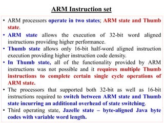
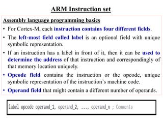
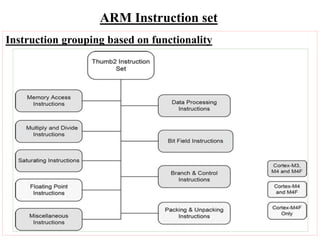
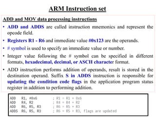
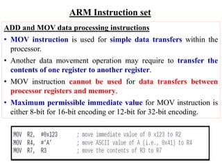
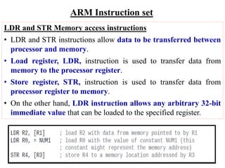
10211CS109 – Microprocessor and Microcontroller
2023 -24 Winter Semester
ARM – Advanced RISC Machine
Unit IV – ARM Processor instruction sets
SCHOOL OF COMPUTING
DEPARTMENT OF COMPUTER SCIENCE AND ENGINEERING
B.Tech – Computer Science & Engineering
Dr. G. Dhanabalan
Associate Professor SoC / CSE
ARM Instruction set
• ARM processors operate in two states; ARM state and Thumb
state.
• ARM state allows the execution of 32-bit word aligned
instructions providing higher performance.
• Thumb state allows only 16-bit half-word aligned instruction
execution providing higher instruction code density.
• In Thumb state, all of the functionality provided by ARM
instructions was not possible and it requires multiple Thumb
instructions to complete certain single cycle operations of
ARM state.
• The processors that supported both 32-bit as well as 16-bit
instructions required to switch between ARM state and Thumb
state incurring an additional overhead of state switching.
• Third operating state, Jazelle state – byte-aligned Java byte
codes with variable word length.
ARM Instruction set
Assembly language programming basics
• For Cortex-M, each instruction contains four different fields.
• The left-most field called label is an optional field with unique
symbolic representation.
• If an instruction has a label in front of it, then it can be used to
determine the address of that instruction and correspondingly of
that memory location uniquely.
• Opcode field contains the instruction or the opcode, unique
symbolic representation of the instruction’s machine code.
• Operand field that might contain a different number of operands.
ARM Instruction set
Instruction grouping based on functionality
ARM Instruction set
ADD and MOV data processing instructions
• ADD and ADDS are called instruction mnemonics and represent the
opcode field.
• Registers R1 - R6 and immediate value #0x123 are the operands.
• # symbol is used to specify an immediate value or number.
• Integer value following the # symbol can be specified in different
formats, hexadecimal, decimal, or ASCII character format.
• ADD instruction performs addition of operands, result is stored in the
destination operand. Suffix S in ADDS instruction is responsible for
updating the condition code flags in the application program status
register in addition to performing addition.
ARM Instruction set
ADD and MOV data processing instructions
• MOV instruction is used for simple data transfers within the
processor.
• Another data movement operation may require to transfer the
contents of one register to another register.
• MOV instruction cannot be used for data transfers between
processor registers and memory.
• Maximum permissible immediate value for MOV instruction is
either 8-bit for 16-bit encoding or 12-bit for 32-bit encoding.
ARM Instruction set
LDR and STR Memory access instructions
• LDR and STR instructions allow data to be transferred between
processor and memory.
• Load register, LDR, instruction is used to transfer data from
memory to the processor register.
• Store register, STR, instruction is used to transfer data from
processor register to memory.
• On the other hand, LDR instruction allows any arbitrary 32-bit
immediate value that can be loaded to the specified register.

unit IV ARM processor instruction set.ppt

  • 1.
    10211CS109 – Microprocessorand Microcontroller 2023 -24 Winter Semester ARM – Advanced RISC Machine Unit IV – ARM Processor instruction sets SCHOOL OF COMPUTING DEPARTMENT OF COMPUTER SCIENCE AND ENGINEERING B.Tech – Computer Science & Engineering Dr. G. Dhanabalan Associate Professor SoC / CSE
  • 2.
    ARM Instruction set •ARM processors operate in two states; ARM state and Thumb state. • ARM state allows the execution of 32-bit word aligned instructions providing higher performance. • Thumb state allows only 16-bit half-word aligned instruction execution providing higher instruction code density. • In Thumb state, all of the functionality provided by ARM instructions was not possible and it requires multiple Thumb instructions to complete certain single cycle operations of ARM state. • The processors that supported both 32-bit as well as 16-bit instructions required to switch between ARM state and Thumb state incurring an additional overhead of state switching. • Third operating state, Jazelle state – byte-aligned Java byte codes with variable word length.
  • 3.
    ARM Instruction set Assemblylanguage programming basics • For Cortex-M, each instruction contains four different fields. • The left-most field called label is an optional field with unique symbolic representation. • If an instruction has a label in front of it, then it can be used to determine the address of that instruction and correspondingly of that memory location uniquely. • Opcode field contains the instruction or the opcode, unique symbolic representation of the instruction’s machine code. • Operand field that might contain a different number of operands.
  • 4.
    ARM Instruction set Instructiongrouping based on functionality
  • 5.
    ARM Instruction set ADDand MOV data processing instructions • ADD and ADDS are called instruction mnemonics and represent the opcode field. • Registers R1 - R6 and immediate value #0x123 are the operands. • # symbol is used to specify an immediate value or number. • Integer value following the # symbol can be specified in different formats, hexadecimal, decimal, or ASCII character format. • ADD instruction performs addition of operands, result is stored in the destination operand. Suffix S in ADDS instruction is responsible for updating the condition code flags in the application program status register in addition to performing addition.
  • 6.
    ARM Instruction set ADDand MOV data processing instructions • MOV instruction is used for simple data transfers within the processor. • Another data movement operation may require to transfer the contents of one register to another register. • MOV instruction cannot be used for data transfers between processor registers and memory. • Maximum permissible immediate value for MOV instruction is either 8-bit for 16-bit encoding or 12-bit for 32-bit encoding.
  • 7.
    ARM Instruction set LDRand STR Memory access instructions • LDR and STR instructions allow data to be transferred between processor and memory. • Load register, LDR, instruction is used to transfer data from memory to the processor register. • Store register, STR, instruction is used to transfer data from processor register to memory. • On the other hand, LDR instruction allows any arbitrary 32-bit immediate value that can be loaded to the specified register.