Addressing modes
2
When accessingan operand for a data processing or
movement instruction, there are several standard
techniques used to specify the desired location. Most
processors support several of these addressing modes
3.
1. Immediate addressing:the desired value is presented as a binary
value in the instruction.
2. Absolute addressing: the instruction contains the full binary address
of
the desired value in memory.
3. Indirect addressing: the instruction contains the binary address of a
memory location that contains the binary address of the desired value.
4.Register addressing: the desired value is in a register, and the
instruction contains the register number.
5.Register indirect addressing: the instruction contains the number
of a register which contains the address of the value in memory.
3
Addressing modes
4.
6.Base plus offsetaddressing: the instruction specifies a register
(the base) and a binary offset to be added to the base to form the
memory address.
7.Base plus index addressing: the instruction specifies a base
register and another register (the index) which is added to the base
to form the memory address.
8.Base plus scaled index addressing: as above, but the index is
multiplied by aconstant (usually the size of the data item, and
usually a power of two) before being added to the base.
9.Stack addressing: an implicit or specified register (the stack
pointer) points to an area of memory (the stack) where data items
are written (pushed) or read (popped) on a last-in-first-out basis.
4
Addressing modes
5.
The ARM instructionset
5
All ARM instructions are 32 bits wide (except the compressed 16-
bit Thumb Instructions ) and are aligned on 4-byte boundaries in
memory.
The most notable features of the ARM instruction set are:
The load-store architecture;
3-address data processing instructions (that is, the two source
operand
registers and the result register are all independently specified);
conditional execution of every instruction;
the inclusion of very powerful load and store multiple register
instructions;
the ability to perform a general shift operation and a general ALU
operation in a single instruction that executes in a single clock cycle;
open instruction set extension through the coprocessor instruction
set, including adding new registers and data types to the
programmer's model;
a very dense 16-bit compressed representation of the instruction set
6.
Addressing modes
6
Memoryis addressed by generating the Effective Address
(EA) of the operand by adding a signed offset to the
contents of a base register Rn.
Pre-indexed mode:
EA is the sum of the contents of the base register Rn and an
offset value.
Pre-indexed with writeback:
EA is generated the same way as pre-indexed mode.
EA is written back into Rn.
Post-indexed mode:
EA is the contents of Rn.
Offset is then added to this address and the result is
written
back to Rn.
7.
Addressing modes (contd..)
7
Relative addressing mode:
Program Counter (PC) is used as a base register.
Pre-indexed addressing mode with immediate offset
No absolute addressing mode available in the ARM
processor.
Offset is specified as:
Immediate value in the instruction itself.
Contents of a register specified in the instruction.
8.
Thumb
8
Thumb is a16-bit instruction set
– Optimized for code density from C code
– Improved performance form narrow memory
– Subset of the functionality of the ARM instruction
set
Core has two execution states – ARM and
Thumb
– Switch between them using BX instruction
Thumb has characteristic features:
– Most Thumb instructions are executed
unconditionally
– Many Thumb data process instruction use a 2-
address format
–
9.
I/O System
9
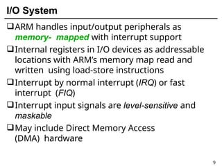
ARM handlesinput/output peripherals as
memory- mapped with interrupt support
Internal registers in I/O devices as addressable
locations with ARM’s memory map read and
written using load-store instructions
Interrupt by normal interrupt (IRQ) or fast
interrupt (FIQ)
Interrupt input signals are level-sensitive and
maskable
May include Direct Memory Access
(DMA) hardware
11.
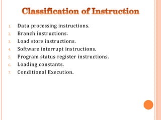
1. Data processinginstructions.
2. Branch instructions.
3. Load store instructions.
4. Software interrupt instructions.
5. Program status register instructions.
6. Loading constants.
7. Conditional Execution.
12.
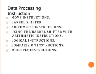
a) MOVE INSTRUCTIONS.
b)BARREL SHIFTER.
c) ARITHMETIC INSTRUCTIONS.
d) USING THE BARREL SHIFTER WITH
ARITHMETIC INSTRUCTIONS.
e) LOGICAL INSTRUCTIONS.
f) COMPARISION INSTRUCTIONS.
g) MULTIPLY INSTRUCTIONS.
Data Processing
Instruction
13.
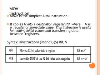
Move isthe simplest ARM instruction.
It copies N into a destination register Rd, where N is
a register or immediate value. This instruction is useful
for setting initial values and transferring data
between registers.
Syntax: <instruction>{<cond>}{S} Rd, N
MOV
Instruction
14.
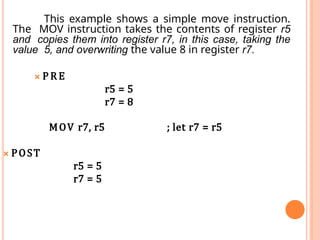
This example showsa simple move instruction.
The MOV instruction takes the contents of register r5
and copies them into register r7, in this case, taking the
value 5, and overwriting the value 8 in register r7.
🞭 P R E
r5 = 5
r7 = 8
MOV r7, r5 ; let r7 = r5
🞭 POST
r5 = 5
r7 = 5
15.
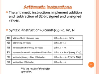
The arithmeticinstructions implement addition
and subtraction of 32-bit signed and unsigned
values.
Syntax: <instruction>{<cond>}{S} Rd, Rn, N
14
N is the result of the shifter
operation.
16.
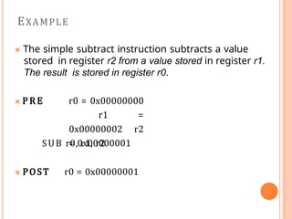
🞭 The simplesubtract instruction subtracts a value
stored in register r2 from a value stored in register r1.
The result is stored in register r0.
🞭 P R E r0 = 0x00000000
r1 =
0x00000002 r2
= 0x00000001
SUB r0, r1, r2
🞭 POST r0 = 0x00000001
EXAMPLE
17.
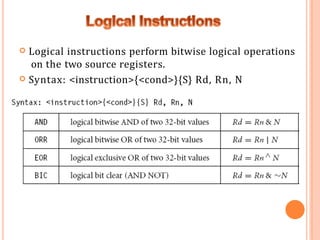
Logical instructionsperform bitwise logical operations
on the two source registers.
Syntax: <instruction>{<cond>}{S} Rd, Rn, N
18.
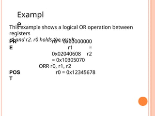
This example showsa logical OR operation between
registers
r1 and r2. r0 holds the result.
PR
E
r0 = 0x00000000
r1 =
0x02040608 r2
= 0x10305070
ORR r0, r1, r2
POS
T
r0 = 0x12345678
Exampl
e
19.
Comparison
Instructions
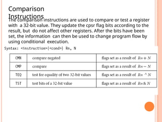
The comparison instructionsare used to compare or test a register
with a 32-bit value. They update the cpsr flag bits according to the
result, but do not affect other registers. After the bits have been
set, the information can then be used to change program flow by
using conditional execution.
20.
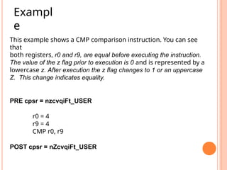
This example showsa CMP comparison instruction. You can see
that
both registers, r0 and r9, are equal before executing the instruction.
The value of the z flag prior to execution is 0 and is represented by a
lowercase z. After execution the z flag changes to 1 or an uppercase
Z. This change indicates equality.
PRE cpsr = nzcvqiFt_USER
r0 = 4
r9 = 4
CMP r0, r9
POST cpsr = nZcvqiFt_USER
Exampl
e
21.
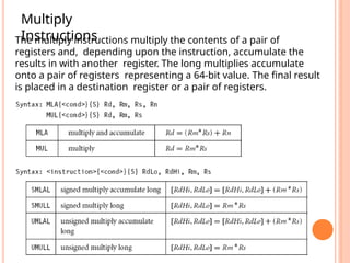
Multiply
Instructions
The multiply instructionsmultiply the contents of a pair of
registers and, depending upon the instruction, accumulate the
results in with another register. The long multiplies accumulate
onto a pair of registers representing a 64-bit value. The final result
is placed in a destination register or a pair of registers.
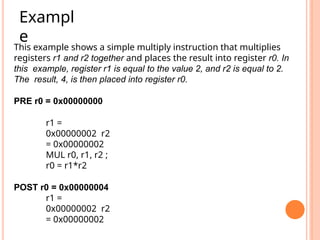
22.
This example showsa simple multiply instruction that multiplies
registers r1 and r2 together and places the result into register r0. In
this example, register r1 is equal to the value 2, and r2 is equal to 2.
The result, 4, is then placed into register r0.
PRE r0 = 0x00000000
r1 =
0x00000002 r2
= 0x00000002
MUL r0, r1, r2 ;
r0 = r1*r2
POST r0 = 0x00000004
r1 =
0x00000002 r2
= 0x00000002
Exampl
e
23.
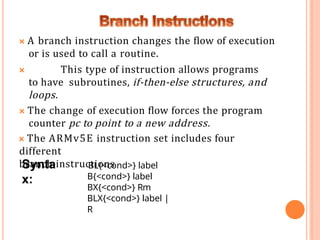
🞭 A branchinstruction changes the flow of execution
or is used to call a routine.
🞭 This type of instruction allows programs
to have subroutines, if-then-else structures, and
loops.
🞭 The change of execution flow forces the program
counter pc to point to a new address.
🞭 The ARMv5E instruction set includes four
different
branch instructions
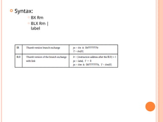
Synta
x:
BL{<cond>} label
B{<cond>} label
BX{<cond>} Rm
BLX{<cond>} label |
R
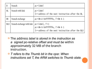
24.
The addresslabel is stored in the instruction as
a signed pc-relative offset and must be within
approximately 32 MB of the branch
instruction.
T refers to the Thumb bit in the cpsr. When
instructions set T, the ARM switches to Thumb state.
25.
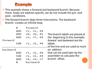
This exampleshows a forward and backward branch. Because
these loops are address specific, we do not include the pre- and
post- conditions.
The forward branch skips three instructions. The backward
branch creates an infinite loop.
The branch labels are placed at
the beginning In this example,
forward and backward are the
labels.
of the line and are used to mark
an address
that can be used later by the
assembler to calculate the
branch offset.
26.
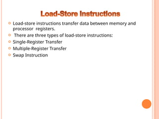
Load-store instructionstransfer data between memory and
processor registers.
There are three types of load-store instructions:
Single-Register Transfer
Multiple-Register Transfer
Swap Instruction
27.
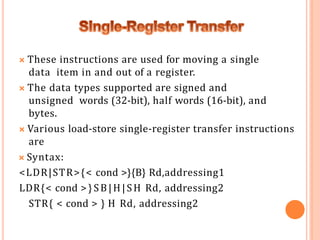
🞭 These instructionsare used for moving a single
data item in and out of a register.
🞭 The data types supported are signed and
unsigned words (32-bit), half words (16-bit), and
bytes.
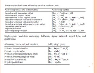
🞭 Various load-store single-register transfer instructions
are
🞭 Syntax:
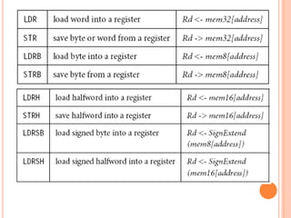
<LDR|STR>{< cond >}{B} Rd,addressing1
LDR{< cond >}SB|H|SH Rd, addressing2
STR{ < cond > } H Rd, addressing2
29.
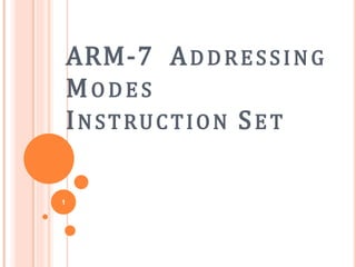
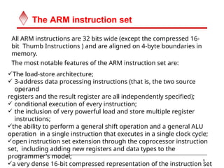
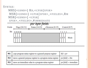
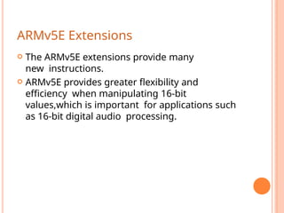
; load registerr0 with the contents of the memory address
;pointed to by register r1.
LDR r0, [r1] ; = LDR r0, [r1, #0]
; store the contents of register r0 to the memory address
;pointed to by register r1.
STR r0, [r1] ; = STR r0, [r1, #0]
The first instruction loads a word from the address stored in register
r1 and places it into register r0. The second instruction goes the
other way by storing the contents of register r0 to the address
contained in register r1. The offset from register r1 is zero. Register
r1 is called th2
e8
base address register.
31.
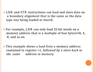
🞭 LDR andSTR instructions can load and store data on
a boundary alignment that is the same as the data
type size being loaded or stored.
🞭 For example, LDR can only load 32-bit words on a
memory address that is a multiple of four bytes—0, 4,
8, and so on.
🞭 This example shows a load from a memory address
contained in register r1, followed by a store back to
the same address in memory.
32.
The firstinstruction loads a word from the
address stored in register r1 and places it into
register r0.
The second instruction goes the other way by storing
the contents of register r0 to the address contained in
register r1.
The offset from register r1 is zero. Register r1 is called
the base address register.
33.
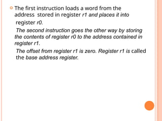
The swap instructionis a special case of a load-store instruction. It
swaps the contents of memory with the contents of a register. This
instruction is an atomic operation—it reads and writes a location in
the same bus operation, preventing any other instruction from
reading or writing to that location until it completes.
Swap
Instruction
34.
33
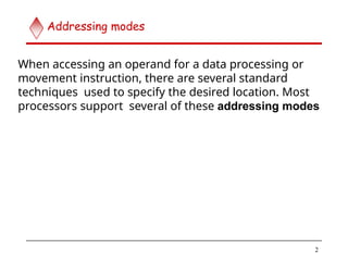
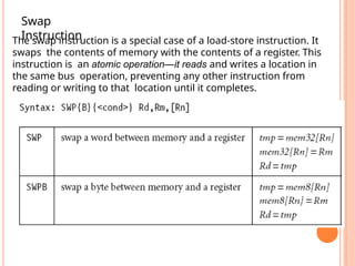
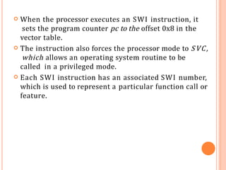
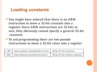
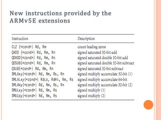
The swap instructionloads a word from memory into register
r0 and
overwrites the memory with register r1.
PRE mem32[0x9000] = 0x12345678
r0 =
0x00000000 r1
= 0x11112222
r2 =
0x00009000
SWP r0,
r1, [r2]
POST mem32[0x9000]
= 0x11112222
r0 =
0x12345678 r1
= 0x11112222
r2 =
0x00009000
35.
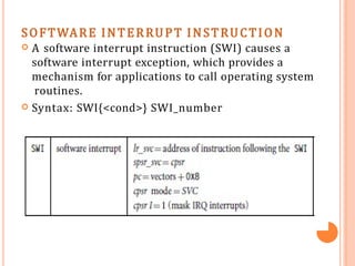
SOFTWARE INTERRUPT INSTRUCTION
A software interrupt instruction (SWI) causes a
software interrupt exception, which provides a
mechanism for applications to call operating system
routines.
Syntax: SWI{<cond>} SWI_number
36.
When theprocessor executes an SWI instruction, it
sets the program counter pc to the offset 0x8 in the
vector table.
The instruction also forces the processor mode to SVC,
which allows an operating system routine to be
called in a privileged mode.
Each SWI instruction has an associated SWI number,
which is used to represent a particular function call or
feature.
37.
EXAMPLE
🞭 Here wehave a simple example of an SWI call with
SWI number 0x123456, used by ARM toolkits as a
debugging SWI. Typically the SWI instruction is
executed in user mode.
🞭 P R E cpsr = nzcVqift_USER
pc = 0x00008000
lr = 0x003fffff; lr = r14
r0 = 0x12
0x00008000 SWI 0x123456
🞭 POST cpsr = nzcVqIft_SVC
spsr = nzcVqift_USER
pc = 0x00000008
lr = 0x00008004
r0 = 0x12 36
38.
Since SWIinstructions are used to call operating system
routines, you need some form of parameter passing. This is
achieved using registers. In this example, register r0 is
used to pass the parameter 0x12.
The return values are also passed back via registers. Code
called the SWI handler is required to process the SWI
call. The handler obtains the SWI number using the
address of the executed instruction, which is calculated
from the link register lr.
The SWI number is determined by
SWI_Number = <SWI instruction> AND NOT(0xff000000)
Here the SWI instruction is the actual 32-bit
SWI instruction executed by the processor.
39.
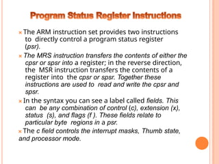
🞭 The ARMinstruction set provides two instructions
to directly control a program status register
(psr).
🞭 The MRS instruction transfers the contents of either the
cpsr or spsr into a register; in the reverse direction,
the MSR instruction transfers the contents of a
register into the cpsr or spsr. Together these
instructions are used to read and write the cpsr and
spsr.
🞭 In the syntax you can see a label called fields. This
can be any combination of control (c), extension (x),
status (s), and flags (f ). These fields relate to
particular byte regions in a psr.
🞭 The c field controls the interrupt masks, Thumb state,
and processor mode.
You mighthave noticed that there is no ARM
instruction to move a 32-bit constant into a
register. Since ARM instructions are 32 bits in
size, they obviously cannot specify a general 32-bit
constant.
To aid programming there are two pseudo
instructions to move a 32-bit value into a register
Loading constants
42.
The first pseudoinstruction writes a 32 bit
constant to a register using whatever instructions
are available. It defaults to a memory read if the
constant cannot be encoded using other
instructions.
The second pseudo instruction writes a relative
address into a register, which will be encoded
using a pc-relative expression.
Syntax:
LDR Rd,
=constant ADR
Rd, label
43.
ARMv5E Extensions
TheARMv5E extensions provide many
new instructions.
ARMv5E provides greater flexibility and
efficiency when manipulating 16-bit
values,which is important for applications such
as 16-bit digital audio processing.
Count Leading ZerosInstruction
The count leading zeros instruction counts
the number of zeros between the most
significant bit and the first bit set to 1.
Example
The first bit set to 1 has 27 zeros preceding it.
CLZ is useful in routines that have to normalize
numbers.
PRE
r1=0b0000000000000000000000000001000
0
CLZ r0, r1
POST
r0 = 27
46.
Most ARMinstructions are conditionally executed—
you can specify that the instruction only executes
if the condition code flags pass a given condition or
test.
By using conditional execution instructions you can
increase performance and code density.
The condition field is a two-letter mnemonic
appended to the instruction mnemonic.
The default mnemonic is AL,or always execute.
Conditional execution reduces the number of
branches, which also reduces the number of
pipeline flushes and thus improves the
performance of the executed code.
Conditional execution depends upon two
components:
the condition field and condition flags.
The condition field is located in the instruction, and
47.
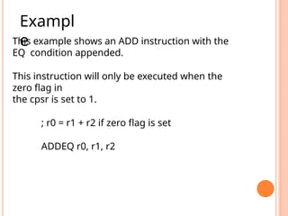
This example showsan ADD instruction with the
EQ condition appended.
This instruction will only be executed when the
zero flag in
the cpsr is set to 1.
; r0 = r1 + r2 if zero flag is set
ADDEQ r0, r1, r2
Exampl
e
48.
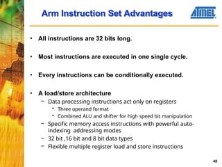
• All instructionsare 32 bits long.
• Most instructions are executed in one single cycle.
• Every instructions can be conditionally executed.
• A load/store architecture
– Data processing instructions act only on registers
• Three operand format
• Combined ALU and shifter for high speed bit manipulation
– Specific memory access instructions with powerful auto-
indexing addressing modes
– 32 bit ,16 bit and 8 bit data types
– Flexible multiple register load and store instructions
Arm Instruction Set Advantages
48
49.
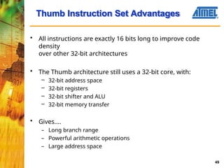
• All instructionsare exactly 16 bits long to improve code
density
over other 32-bit architectures
• The Thumb architecture still uses a 32-bit core, with:
– 32-bit address space
– 32-bit registers
– 32-bit shifter and ALU
– 32-bit memory transfer
• Gives....
– Long branch range
– Powerful arithmetic operations
– Large address space
Thumb Instruction Set Advantages
49
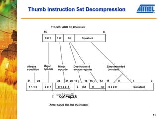
50.
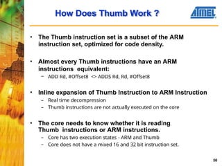
• The Thumbinstruction set is a subset of the ARM
instruction set, optimized for code density.
• Almost every Thumb instructions have an ARM
instructions equivalent:
– ADD Rd, #Offset8 <> ADDS Rd, Rd, #Offset8
• Inline expansion of Thumb Instruction to ARM Instruction
– Real time decompression
– Thumb instructions are not actually executed on the core
• The core needs to know whether it is reading
Thumb instructions or ARM instructions.
– Core has two execution states - ARM and Thumb
– Core does not have a mixed 16 and 32 bit instruction set.
How Does Thumb Work ?
50
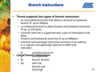
Branch Instructions
52
• Thumbsupports four types of branch instruction:
– an unconditional branch that allows a forward or backward
branch of up to 2Kbytes
– a conditional branch to allow forward and backward branches
of up to 256 bytes
– a branch with link is supported with a pair of instructions that
allow
forward and backwards branches of up to 4Mbytes
– a branch and exchange instruction branches to an address
in a register and optionally switches to ARM code
execution
• List of branch instructions
– B
– B
– BL
– BX
conditional branch
unconditional
branch Branch
with link
Branch and
exchange
53.
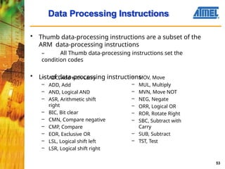
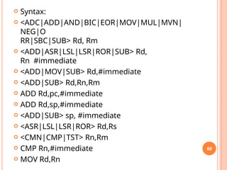
Data Processing Instructions
53
•Thumb data-processing instructions are a subset of the
ARM data-processing instructions
– All Thumb data-processing instructions set the
condition codes
• List of data-processing instructions
– ADC, Add with Carry
– ADD, Add
– AND, Logical AND
– ASR, Arithmetic shift
right
– BIC, Bit clear
– CMN, Compare negative
– CMP, Compare
– EOR, Exclusive OR
– LSL, Logical shift left
– LSR, Logical shift right
– MOV, Move
– MUL, Multiply
– MVN, Move NOT
– NEG, Negate
– ORR, Logical OR
– ROR, Rotate Right
– SBC, Subtract with
Carry
– SUB, Subtract
– TST, Test
54.
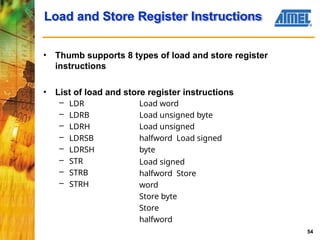
Load and StoreRegister Instructions
54
• Thumb supports 8 types of load and store register
instructions
• List of load and store register instructions
– LDR
– LDRB
– LDRH
– LDRSB
– LDRSH
– STR
– STRB
– STRH
Load word
Load unsigned byte
Load unsigned
halfword Load signed
byte
Load signed
halfword Store
word
Store byte
Store
halfword
55.
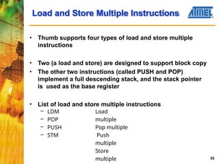
Load and StoreMultiple Instructions
55
• Thumb supports four types of load and store multiple
instructions
• Two (a load and store) are designed to support block copy
• The other two instructions (called PUSH and POP)
implement a full descending stack, and the stack pointer
is used as the base register
• List of load and store multiple instructions
– LDM
– POP
– PUSH
– STM
Load
multiple
Pop multiple
Push
multiple
Store
multiple
56.
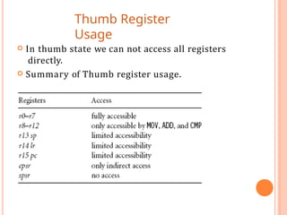
Thumb Register
Usage
Inthumb state we can not access all registers
directly.
Summary of Thumb register usage.
57.
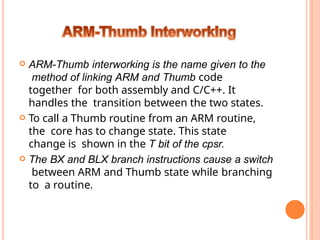
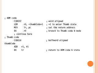
ARM-Thumb interworkingis the name given to the
method of linking ARM and Thumb code
together for both assembly and C/C++. It
handles the transition between the two states.
To call a Thumb routine from an ARM routine,
the core has to change state. This state
change is shown in the T bit of the cpsr.
The BX and BLX branch instructions cause a switch
between ARM and Thumb state while branching
to a routine.
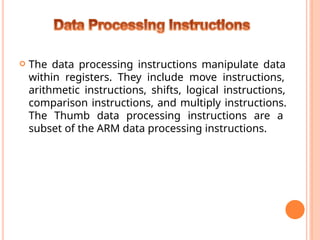
The dataprocessing instructions manipulate data
within registers. They include move instructions,
arithmetic instructions, shifts, logical instructions,
comparison instructions, and multiply instructions.
The Thumb data processing instructions are a
subset of the ARM data processing instructions.
61
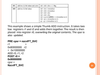
This example showsa simple Thumb ADD instruction. It takes two
low registers r1 and r2 and adds them together. The result is then
placed into register r0, overwriting the original contents. The cpsr is
also updated.
PRE cpsr = nzcvIFT_SVC
r1 =
0x80000000 r2
= 0x10000000
ADD r0, r1, r2
POST r0 =
0x90000000
cpsr =
NzcvIFT_SVC
63.
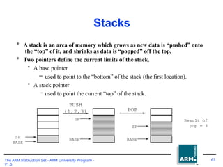
Stacks
* A stackis an area of memory which grows as new data is “pushed” onto
the “top” of it, and shrinks as data is “popped” off the top.
* Two pointers define the current limits of the stack.
• A base pointer
– used to point to the “bottom” of the stack (the first location).
• A stack pointer
– used to point the current “top” of the stack.
PUSH
SP
BASE
{1,2,3}
SP 3
2
1
BASE
POP
2
1
Result of
pop = 3
BASE
SP
The ARM Instruction Set - ARM University Program -
V1.0
63
64.
Stack Operation
The ARMInstruction Set - ARM University Program -
V1.0
64
* Traditionally, a stack grows down in memory, with the last “pushed”
value at the lowest address. The ARM also supports ascending stacks,
where the stack structure grows up through memory.
* The value of the stack pointer can either:
• Point to the last occupied address (Full stack)
– and so needs pre-decrementing (ie before the push)
• Point to the next occupied address (Empty stack)
– and so needs post-decrementing (ie after the push)
* The stack type to be used is given by the postfix to the instruction:
• STMFD / LDMFD : Full Descending stack
• STMFA / LDMFA : Full Ascending stack.
• STMED / LDMED : Empty Descending stack
• STMEA / LDMEA : Empty Ascending stack
* Note: ARM Compiler will always use a Full descending stack.
65.
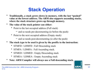
Stack Examples
STMFD sp!,
{r0,r1,r3-r5}
r5
r4
r3
r1
r0
S
P
OldSP
STMED sp!,
{r0,r1,r3-r5}
r5
r4
r3
r1
r0
S
P
Old SP
r5
r4
r3
r1
r0
STMFA sp!,
{r0,r1,r3-r5}
S
P
Old SP 0x40
0
0x41
8
0x3e
8
STMEA sp!,
{r0,r1,r3-r5}
r5
r4
r3
r1
r0
S
P
Old SP
The ARM Instruction Set - ARM University Program -
V1.0
65
66.
Stacks and Subroutines
TheARM Instruction Set - ARM University Program -
V1.0
66
* One use of stacks is to create temporary register workspace for
subroutines. Any registers that are needed can be pushed onto the stack
at the start of the subroutine and popped off again at the end so as to
restore them before return to the caller :
STMFD sp!,{r0-r12,
........
........
lr} ;
;
stack all registers
and the return address
LDMFD sp!,{r0-r12, pc} ; load all the registers
; and return automatically
* See the chapter on the ARM Procedure Call Standard in the SDT
Reference Manual for further details of register usage within
subroutines.
* If the pop instruction also had the ‘S’ bit set (using ‘^’) then the transfer
of the PC when in a priviledged mode would also cause the SPSR to be
copied into the CPSR (see exception handling module).
67.
Direct functionality of
BlockData Transfer
The ARM Instruction Set - ARM University Program -
V1.0
67
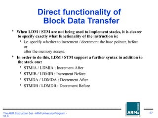
* When LDM / STM are not being used to implement stacks, it is clearer
to specify exactly what functionality of the instruction is:
• i.e. specify whether to increment / decrement the base pointer, before
or
after the memory access.
* In order to do this, LDM / STM support a further syntax in addition to
the stack one:
• STMIA / LDMIA : Increment After
• STMIB / LDMIB : Increment Before
• STMDA / LDMDA : Decrement After
• STMDB / LDMDB : Decrement Before
68.
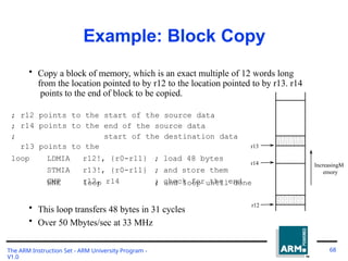
Example: Block Copy
•Copy a block of memory, which is an exact multiple of 12 words long
from the location pointed to by r12 to the location pointed to by r13. r14
points to the end of block to be copied.
;
;
;
r12
r14
r13
points
points
points
to
to
to
the
the
the
start of the source data
end of the source data
start of the destination data
loop LDMIA r12!, {r0-r11} ; load 48 bytes
STMIA r13!, {r0-r11} ; and store them
CMP r12, r14 ; check for the end
BNE loop ; and loop until done
• This loop transfers 48 bytes in 31 cycles
• Over 50 Mbytes/sec at 33 MHz
r13
r14
r12
IncreasingM
emory
The ARM Instruction Set - ARM University Program -
V1.0
68
69.
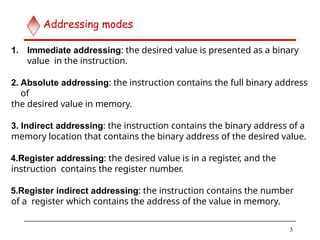
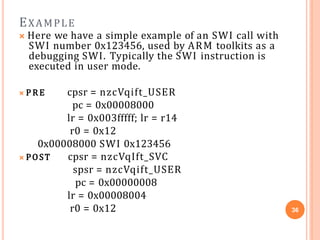
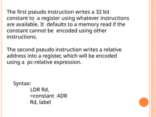
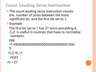
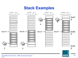
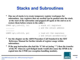
* Atomic operationof a memory read followed by a memory write
which moves byte or word quantities between registers and
memory.
* Syntax:
• SWP{<cond>}{B} Rd, Rm, [Rn]
Swap and Swap Byte
Instructions
R
* Thus tmo implement an actual swap of contents make Rd =
Rm.
* The compiler cannot produce this instruction.
Rd
Rn
3
2
1
tem
p
The ARM Instruction Set - ARM University Program -
V1.0
69
Memor
y
70.
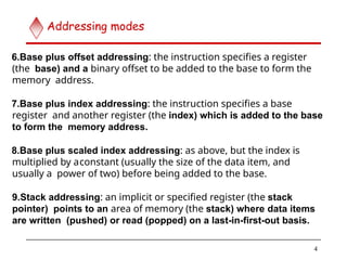
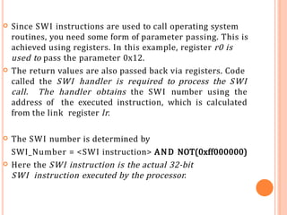
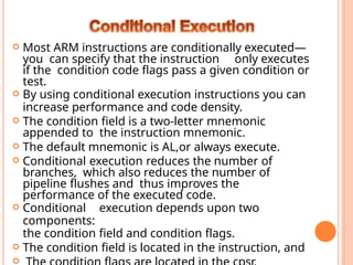
* Atomic operationof a memory read followed by a memory write
which moves byte or word quantities between registers and
memory.
* Syntax:
• SWP{<cond>}{B} Rd, Rm, [Rn]
Swap and Swap Byte
Instructions
R
* Thus tmo implement an actual swap of contents make Rd =
Rm.
* The compiler cannot produce this instruction.
Rd
Rn
3
2
1
tem
p
The ARM Instruction Set - ARM University Program -
V1.0
70
Memor
y
71.
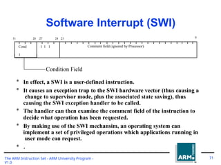
Software Interrupt (SWI)
Cond
1
11 1 Comment field (ignored by Processor)
28 27
31 24 23 0
Condition Field
* In effect, a SWI is a user-defined instruction.
* It causes an exception trap to the SWI hardware vector (thus causing a
change to supervisor mode, plus the associated state saving), thus
causing the SWI exception handler to be called.
* The handler can then examine the comment field of the instruction to
decide what operation has been requested.
* By making use of the SWI mechansim, an operating system can
implement a set of privileged operations which applications running in
user mode can request.
* .
The ARM Instruction Set - ARM University Program -
V1.0
71
72.
The Thumbsoftware interrupt (SWI)
instruction causes a software interrupt
exception. If any interrupt or exception flag
is raised in Thumb state,the processor
automatically reverts back to ARM state to
handle the exception
Syntax: SWI immediate
![; load register r0 with the contents of the memory address
;pointed to by register r1.
LDR r0, [r1] ; = LDR r0, [r1, #0]
; store the contents of register r0 to the memory address
;pointed to by register r1.
STR r0, [r1] ; = STR r0, [r1, #0]
The first instruction loads a word from the address stored in register
r1 and places it into register r0. The second instruction goes the
other way by storing the contents of register r0 to the address
contained in register r1. The offset from register r1 is zero. Register
r1 is called th2
e8
base address register.](https://image.slidesharecdn.com/armunit3ppt-250630101819-bb0a05dd/85/ARM-7-ADDRESSING-MODES-INSTRUCTION-SET-29-320.jpg)
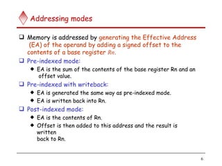
![33
The swap instruction loads a word from memory into register
r0 and
overwrites the memory with register r1.
PRE mem32[0x9000] = 0x12345678
r0 =
0x00000000 r1
= 0x11112222
r2 =
0x00009000
SWP r0,
r1, [r2]
POST mem32[0x9000]
= 0x11112222
r0 =
0x12345678 r1
= 0x11112222
r2 =
0x00009000](https://image.slidesharecdn.com/armunit3ppt-250630101819-bb0a05dd/85/ARM-7-ADDRESSING-MODES-INSTRUCTION-SET-34-320.jpg)
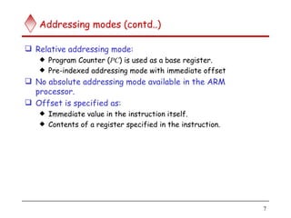
![* Atomic operation of a memory read followed by a memory write
which moves byte or word quantities between registers and
memory.
* Syntax:
• SWP{<cond>}{B} Rd, Rm, [Rn]
Swap and Swap Byte
Instructions
R
* Thus tmo implement an actual swap of contents make Rd =
Rm.
* The compiler cannot produce this instruction.
Rd
Rn
3
2
1
tem
p
The ARM Instruction Set - ARM University Program -
V1.0
69
Memor
y](https://image.slidesharecdn.com/armunit3ppt-250630101819-bb0a05dd/85/ARM-7-ADDRESSING-MODES-INSTRUCTION-SET-69-320.jpg)
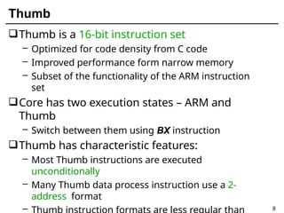
![* Atomic operation of a memory read followed by a memory write
which moves byte or word quantities between registers and
memory.
* Syntax:
• SWP{<cond>}{B} Rd, Rm, [Rn]
Swap and Swap Byte
Instructions
R
* Thus tmo implement an actual swap of contents make Rd =
Rm.
* The compiler cannot produce this instruction.
Rd
Rn
3
2
1
tem
p
The ARM Instruction Set - ARM University Program -
V1.0
70
Memor
y](https://image.slidesharecdn.com/armunit3ppt-250630101819-bb0a05dd/85/ARM-7-ADDRESSING-MODES-INSTRUCTION-SET-70-320.jpg)