Download to read offline
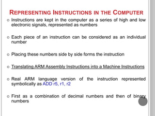
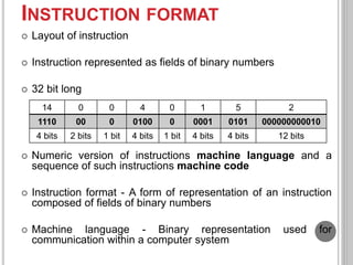
![ARM FIELDS (2)
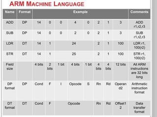
ADD r3, r3, #4 ; r3=r3+4
Constant 4 is placed in operand 2 field and the I field is set to 1
LDR r5, [r3, #32] ; Temporary register r5 gets A[8]
Load and store use a different instruction format from above
with 6 fields
Field F = 1 => Tell ARM that format is different
Data transfer instruction format
Opcode field 24 => instruction perform load word
Offset2 field has 32 as the offset to add to the base register
14 0 1 4 0 3 3 4
Cond F Opcode Rn Rd Offset2
4 bits 2 bits 6 bits 4 bits 4 bits 12 bits](https://image.slidesharecdn.com/l3representinginstructionsinthecomputer-220916061822-6b505a6c/85/L3_Representing-Instructions-in-the-Computer-pptx-8-320.jpg)
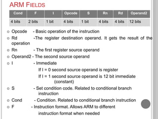
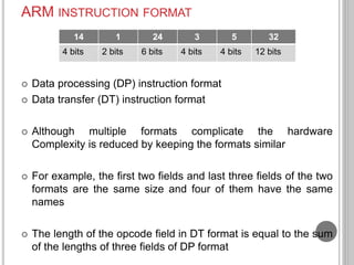
![TRANSLATING ARM ASSEMBLY LANGUAGE
INTO MACHINE LANGUAGE
Consider an example all the way from what the
programmer writes to what the computer executes
If r3 has the base of the array A and r2 corresponds to h,
the assignment statement
A[30] = h + A[30]; is compiled into
LDR r5, [r3, #120] # Temporary reg r5 gets A[30]
ADD r5, r2, r5 # Temporary reg r5 gets h + A[30]
STR r5, [r3, #120] # Stores h + A[30] back into A[30]
What is the ARM machine language code for these three
instructions?](https://image.slidesharecdn.com/l3representinginstructionsinthecomputer-220916061822-6b505a6c/85/L3_Representing-Instructions-in-the-Computer-pptx-9-320.jpg)


The document discusses how ARM assembly language instructions are represented and encoded in machine language format within computers. It explains that instructions are stored as binary numbers divided into fields. It then describes the specific fields that make up ARM instructions, including opcode, registers, immediates, and condition codes. Finally, it provides examples of how sample ARM assembly instructions would be encoded in both decimal and binary machine language formats.