The document provides information about the ARM processor architecture. It discusses the key aspects of ARM including:
- ARM uses a load-store architecture with fixed-length 32-bit instructions and 3-address instruction formats.
- The main differences between RISC and CISC are that RISC executes one instruction per clock cycle while CISC takes multiple cycles per instruction.
- ARM development tools include a C compiler, assembler, linker, debugger and emulator to allow cross-development for ARM systems.


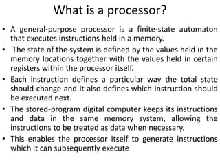


![Addressing modes
Register operands
• ADD R0, R1, R2
Immediate operands
• ADD R3, R3, #1 R3:=R3+1
• AND R8, R7, #0xff R8=R7[7:0]
Shifted register operands
Logical shift left
• MOV R0, R2, LSL #2 R0:=R2<<2
R2 unchanged
Eg: 0…0 0011 0000
Before R2=0x00000030
After R0=0x000000C0
R2=0x00000030](https://image.slidesharecdn.com/mod3-240208055850-9b1de831/85/Mod-3-pptx-43-320.jpg)


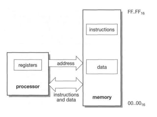
![Q3. In Q1 put the data in memory as constants before
the program runs
ADR r4,TheData ;r4 points to the data area
LDR r1,[r4,#Q] ;load Q into r1
LDR r2,[r4,#R] ;load R into r2
LDR r3,[r4,#S] ;load S into r3
ADD r0,r1,r2 ;add Q and R
ADD r0,r0,r3 ;add S to the total
STR r0,[r4,#P] ;save the result in memory](https://image.slidesharecdn.com/mod3-240208055850-9b1de831/85/Mod-3-pptx-48-320.jpg)