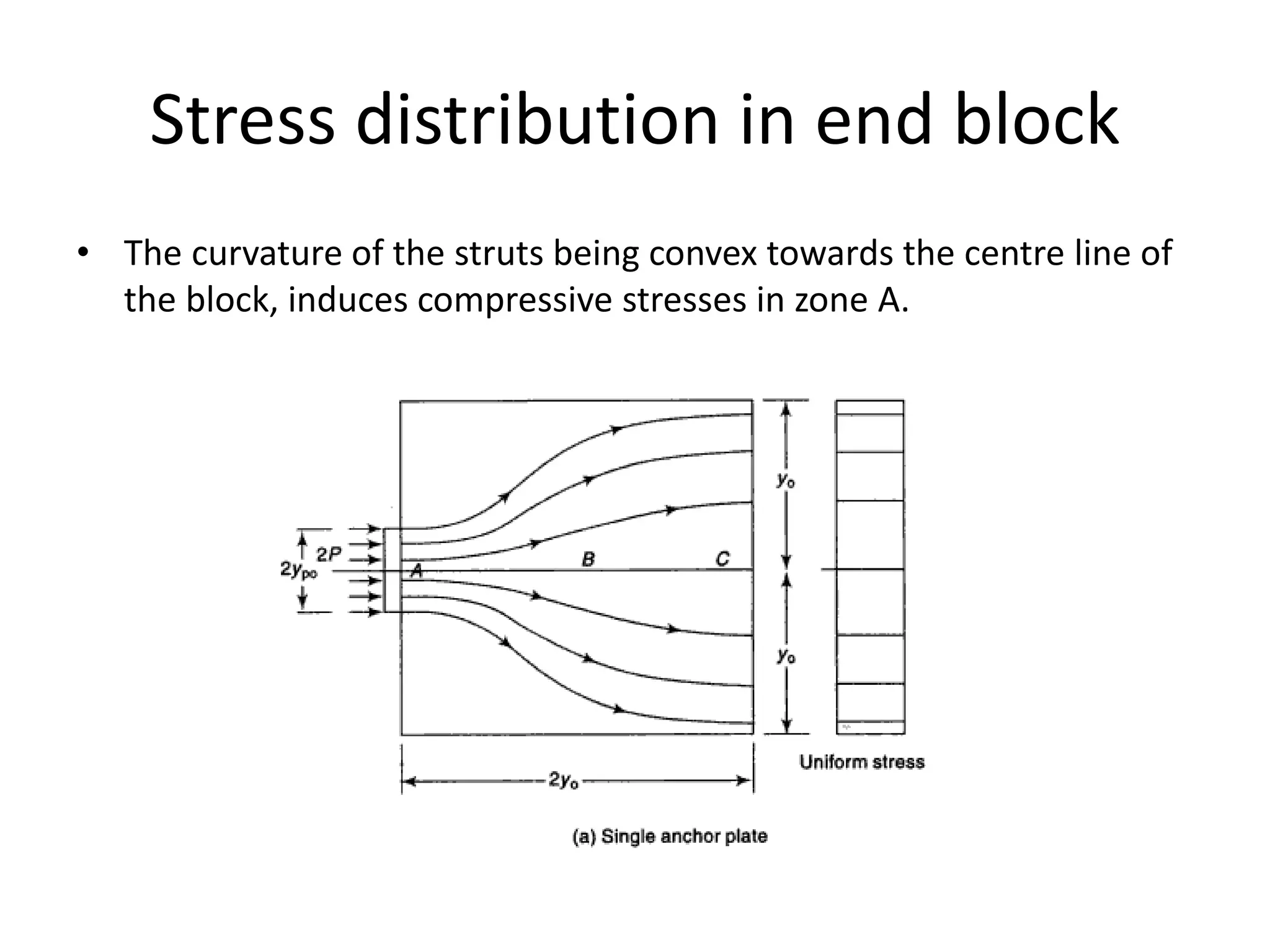
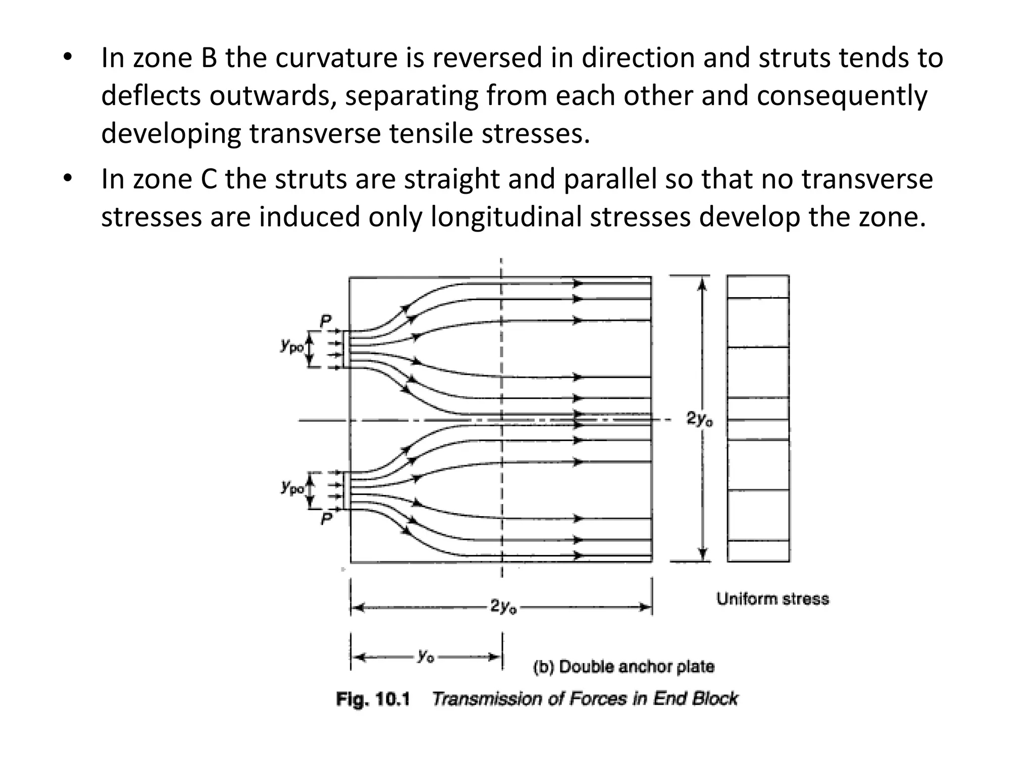
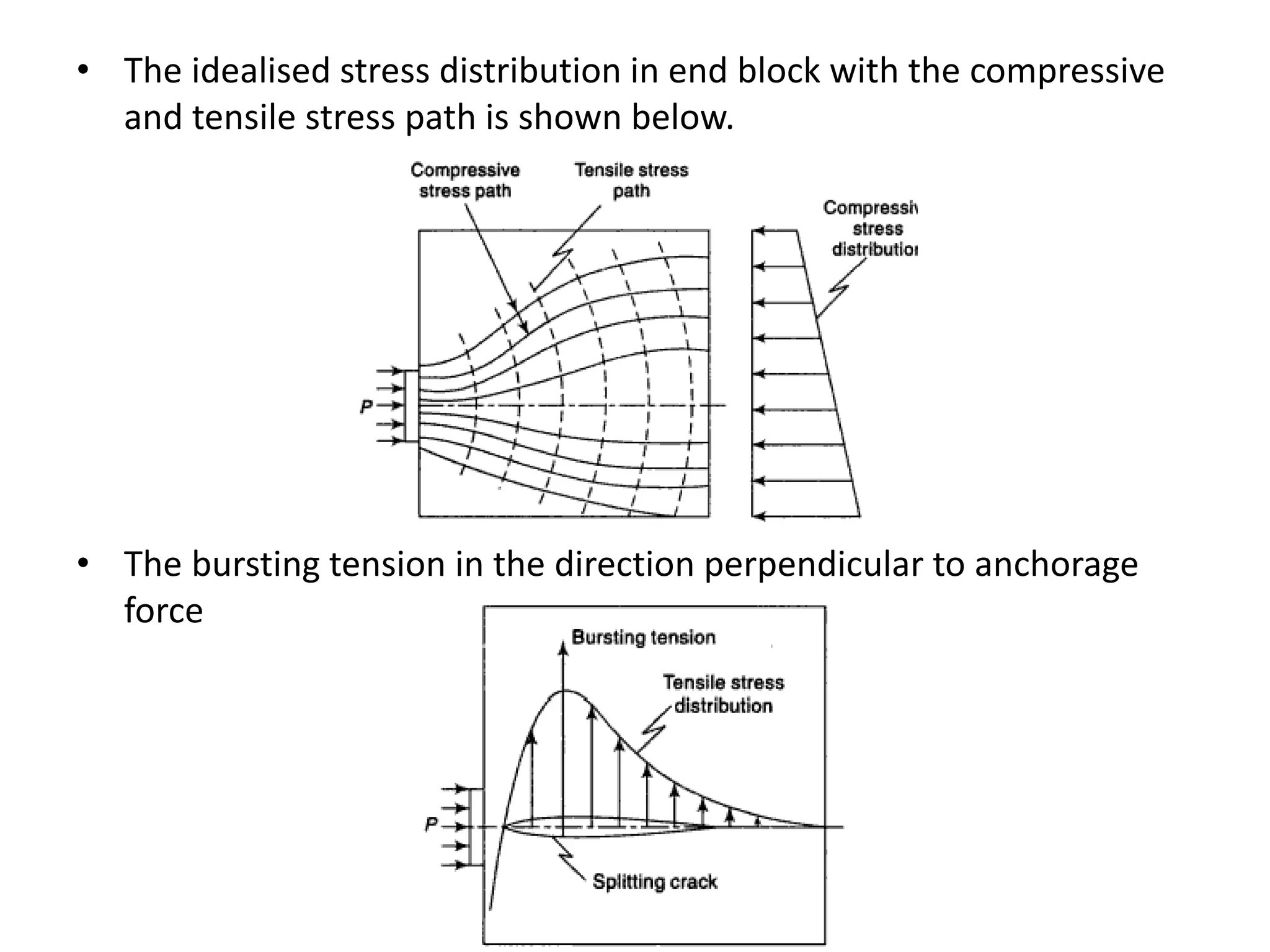
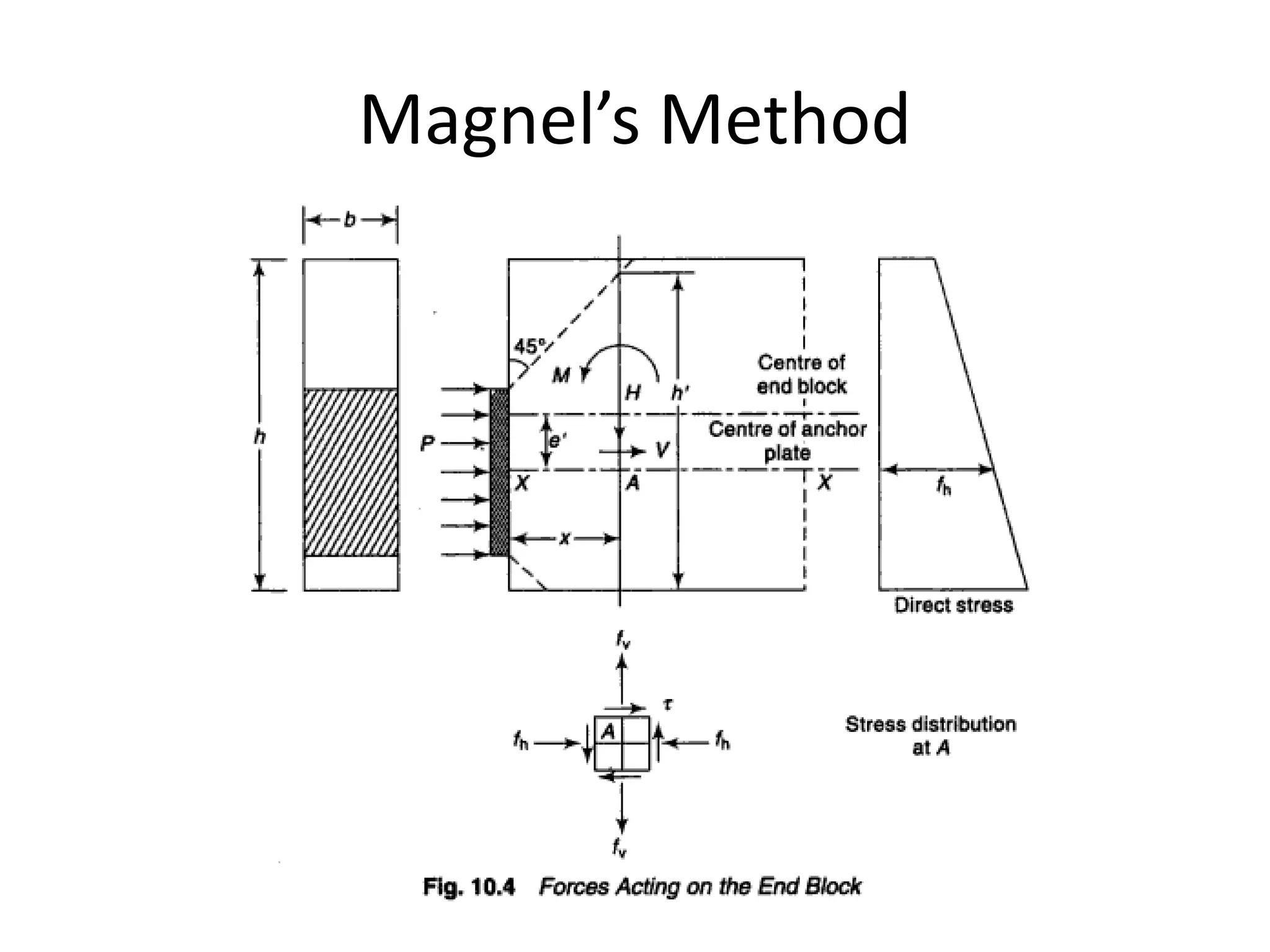
UNIT III
DEFLECTION AND DESIGN
OF ANCHORAGE ZONE
Mr.P.SELVAKUMAR
Assistant Professor
Department of Civil Engineering
Knowledge Institute of Technology, Salem
Stress distribution in end block
• The curvature of the struts being convex towards the centre line of
the block, induces compressive stresses in zone A.
• In zone B the curvature is reversed in direction and struts tends to
deflects outwards, separating from each other and consequently
developing transverse tensile stresses.
• In zone C the struts are straight and parallel so that no transverse
stresses are induced only longitudinal stresses develop the zone.
• The idealised stress distribution in end block with the compressive
and tensile stress path is shown below.
• The bursting tension in the direction perpendicular to anchorage
force
Magnel’s Method
Thank You
KIOT, SALEM / CIVIL ENGINEERING

Unit III deflection and design of anchorage zone

  • 1.
    UNIT III DEFLECTION ANDDESIGN OF ANCHORAGE ZONE Mr.P.SELVAKUMAR Assistant Professor Department of Civil Engineering Knowledge Institute of Technology, Salem
  • 2.
    Stress distribution inend block • The curvature of the struts being convex towards the centre line of the block, induces compressive stresses in zone A.
  • 3.
    • In zoneB the curvature is reversed in direction and struts tends to deflects outwards, separating from each other and consequently developing transverse tensile stresses. • In zone C the struts are straight and parallel so that no transverse stresses are induced only longitudinal stresses develop the zone.
  • 4.
    • The idealisedstress distribution in end block with the compressive and tensile stress path is shown below. • The bursting tension in the direction perpendicular to anchorage force
  • 5.
  • 6.
    Thank You KIOT, SALEM/ CIVIL ENGINEERING