The document discusses storage management and file management as critical components of operating systems, focusing on device management, disk scheduling, and file system interfaces. It covers various mass-storage systems including hard disks, solid-state disks, and magnetic tapes, detailing their physical structures, performance characteristics, and access methods. Additionally, it analyzes disk scheduling algorithms to optimize input/output requests for efficient disk management.


![29
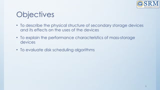
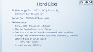
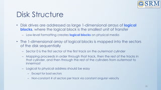
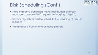
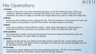
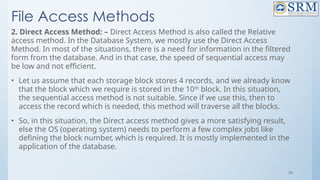
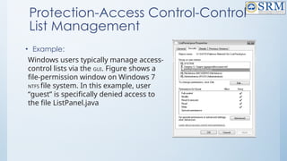
FCFS(contd..)
• Total head movements using FCFS= [(98 – 53) + (183 – 98) + (183 – 41) + (122 –
41) + (122 – 14) + (124 – 14) + (124 – 65) + (67 – 65)]
• = 45 + 85 + 142 + 81 + 108 + 110 + 59 + 2
• =632
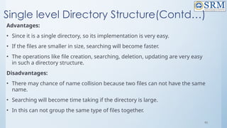
Advantages:
• Every request gets a fair chance
• No indefinite postponement
Disadvantages:
• Does not try to optimize seek time
• May not provide the best possible service](https://image.slidesharecdn.com/18csc205joperatingsystems-unit-5-241109151231-940f7674/85/18CSC205J-Operating-Systemkooks-Unit-5-pptx-29-320.jpg)
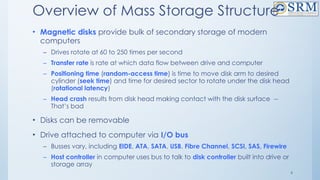
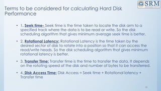
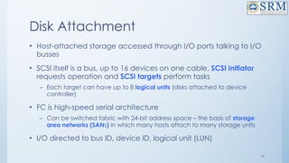
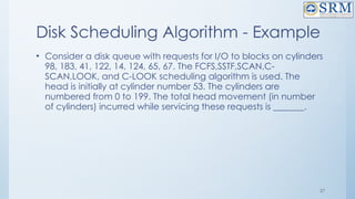
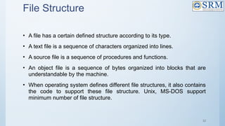
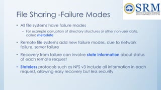
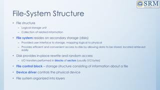
![SSTF(contd…)
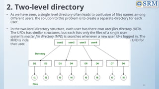
• head is initially at cylinder number 53. The cylinders are numbered from
0 to 199. [98, 183, 41, 122, 14, 124, 65, 67 ]
• 98, 183, 41, 122, 14, 124, 65, 67
31
Total head movement using SSTF=(65-53)+(67-65)+(67-41)+(41-14)+(98-
14)+ (122-98)+(124-122)+(183-124)
=12+2+26+27+84+24+2+59=236)](https://image.slidesharecdn.com/18csc205joperatingsystems-unit-5-241109151231-940f7674/85/18CSC205J-Operating-Systemkooks-Unit-5-pptx-31-320.jpg)
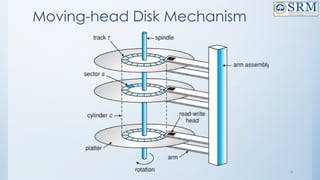
![33
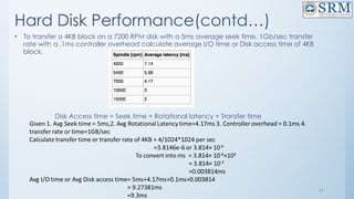
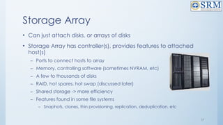
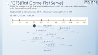
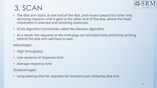
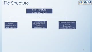
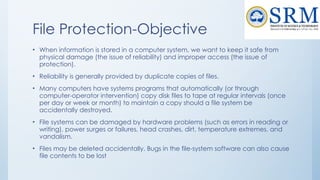
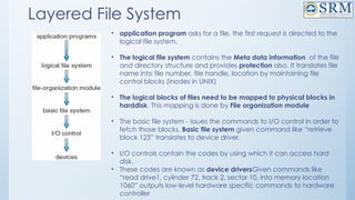
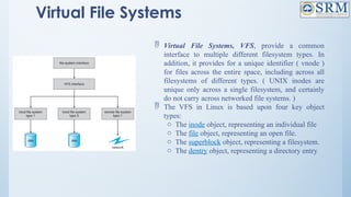
SCAN or Elevator((1st
Solution)
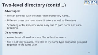
• head is initially at cylinder number 53. The cylinders are numbered
from 0 to 199. [ 98, 183, 41, 122, 14, 124, 65, 67 ]
Total Head Movement using SCAN=[(65-53)+(67-65)+(98-67)+(122-98)+(124-
122)+(183-124)+(199-183)+(199-41)+
(41-14)]
=12+2+31+24+2+59+16+158+27)=331](https://image.slidesharecdn.com/18csc205joperatingsystems-unit-5-241109151231-940f7674/85/18CSC205J-Operating-Systemkooks-Unit-5-pptx-33-320.jpg)
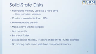
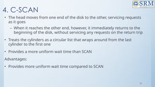
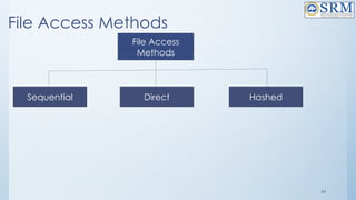
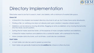
![34
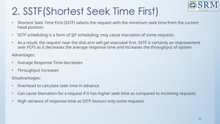
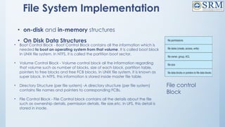
SCAN or Elevator(2nd
Solution)- Best Choice
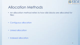
• head is initially at cylinder number 53. The cylinders are numbered
from 0 to 199. [ 98, 183, 41, 122, 14, 124, 65, 67 ]
Total Head Movement using SCAN=[(53-41)+(41-14)+(14-0)+(65-0)+(67-65)+
(98-67)+(122-98)+(124-122)+(183-124)]
=12+27+14+65+2+31+24+59
= 234](https://image.slidesharecdn.com/18csc205joperatingsystems-unit-5-241109151231-940f7674/85/18CSC205J-Operating-Systemkooks-Unit-5-pptx-34-320.jpg)
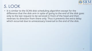
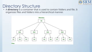
![36
C-SCAN(contd…)
• head is initially at cylinder number 53. The cylinders are numbered from 0
to 199. [ 98, 183, 41, 122, 14, 124, 65, 67 ]
Total Head Movement using C-SCAN=[(65-53)+(67-65)+(98-67)+(122-98)+(124-122)+(183-124)+(199-
183)+(199-0)+(14-0)+(41-14)]
=12+2+31+24+2+59+16+199+14+27)=386](https://image.slidesharecdn.com/18csc205joperatingsystems-unit-5-241109151231-940f7674/85/18CSC205J-Operating-Systemkooks-Unit-5-pptx-36-320.jpg)
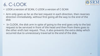
![38
LOOK(Contd…)
• head is initially at cylinder number 53. The cylinders are numbered from
0 to 199. [ 98, 183, 41, 122, 14, 124, 65, 67 ]
Total Head Movement using look=[(65-53)+(67-65)+(98-67)+(122-98)+(124-
122)+ (183-124)+(183-41)+(41-14)]
=12+2+31+24+2+59+142+27)=299](https://image.slidesharecdn.com/18csc205joperatingsystems-unit-5-241109151231-940f7674/85/18CSC205J-Operating-Systemkooks-Unit-5-pptx-38-320.jpg)
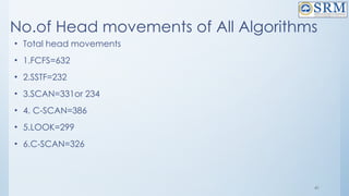
![40
C- LOOK(contd…)
• head is initially at cylinder number 53. The cylinders are numbered
from 0 to 199.
98, 183, 41, 122, 14, 124, 65, 67
Total Head Movement using C-LOOK=[(65-53)+(67-65)+(98-67)+(122-
98)+(124-122)+(183-124)+(183-14)+
(41-14)]
= 12+2+31+24+2+59+169+27)=326](https://image.slidesharecdn.com/18csc205joperatingsystems-unit-5-241109151231-940f7674/85/18CSC205J-Operating-Systemkooks-Unit-5-pptx-40-320.jpg)


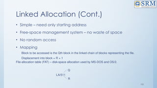


![118
Free-Space Management
Bit vector (n blocks)
…
bit[i] =
0 block[i] free
1 block[i] occupied
(number of bits per word) *
(number of 0-value words) +
offset of first 1 bit](https://image.slidesharecdn.com/18csc205joperatingsystems-unit-5-241109151231-940f7674/85/18CSC205J-Operating-Systemkooks-Unit-5-pptx-118-320.jpg)

![120
Free-Space Management (Cont.)
• Need to protect:
– Pointer to free list
– Bit map
– Must be kept on disk
– Copy in memory and disk may differ
– Cannot allow for block[i] to have a situation where bit[i] = 1 in memory and
bit[i] = 0 on disk
– Solution:
– Set bit[i] = 1 in disk
– Allocate block[i]
– Set bit[i] = 1 in memory](https://image.slidesharecdn.com/18csc205joperatingsystems-unit-5-241109151231-940f7674/85/18CSC205J-Operating-Systemkooks-Unit-5-pptx-120-320.jpg)


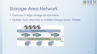
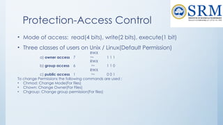
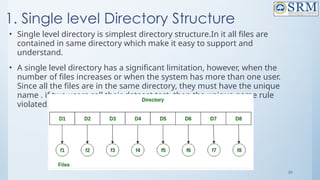
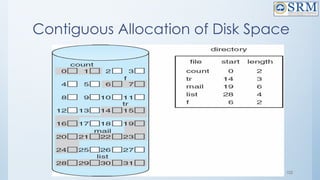
![4.Counting
• This approach stores the address of the first free disk block and a
number n of free contiguous disk blocks that follow the first block.
Every entry in the list would contain:
• Address of first free disk block
• A number n
• For example, in Figure-1, the first entry of the free space list would
be: ([Address of Block 5], 2), because 2 contiguous free blocks
follow block 5.](https://image.slidesharecdn.com/18csc205joperatingsystems-unit-5-241109151231-940f7674/85/18CSC205J-Operating-Systemkooks-Unit-5-pptx-132-320.jpg)