Download as PDF, PPTX
![7/15/14 © 2014 TTI / Mike Mazzatti / teratec.us 5
Fiber Optics
Historical Perspective
• Colladon / Babinet 1840s - Principle of total internal reflection in water jets & bent glass rods.
• Hopkins / Kapany /Snitzer 1950s – Light propagation with cladded fibers for applications of
medicine, defense, even television.
• Charles Kao / Standard Telecommunications Lab Team 1960s – proposed a perfected SiO2 fiber
light pipe for low loss transmission capabilities.
• Keck / Maurer / Schultz at Corning 1970s – proved Kao’s vision through designing and drawing
preforms of chemical vapor deposition glass.
• Kao the 2009 co-winner of the Nobel prize in physics. [courtesy Royal Swedish Academy of
Sciences]](https://image.slidesharecdn.com/demystifyingotdreventanalysiscctapresentation070714-230129101522-1722efdf/85/Demystifying-OTDR-Event-Analysis-CCTA-Presentation-070714-pdf-5-320.jpg)
![8
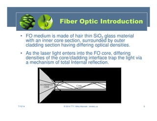
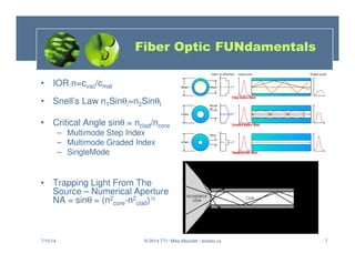
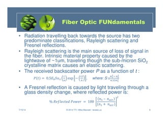
Fiber Optic FUNdamentals
• Losses - Attenuation
– dB or –dB
– Loss vs Wavelength (Loss vs Freq)
See Table
– Rayleigh Scattering Loss ≈ 1.7(0.85/λ)4
– Fresnel Reflections ρ = [(n-1)/(n+1)]2
– ORL Optical Return Loss
– Insertion Losses
– Connectorization Alignment
– Micro/macrobends & Absorption
7/15/14 8
© 2014 TTI / Mike Mazzatti / teratec.us](https://image.slidesharecdn.com/demystifyingotdreventanalysiscctapresentation070714-230129101522-1722efdf/85/Demystifying-OTDR-Event-Analysis-CCTA-Presentation-070714-pdf-8-320.jpg)
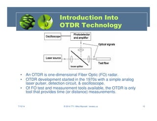
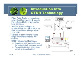
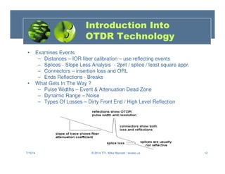
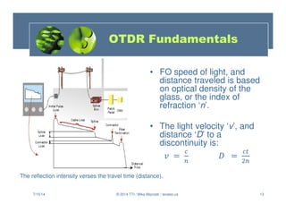
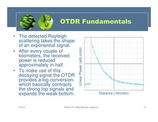
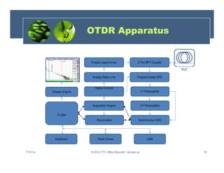
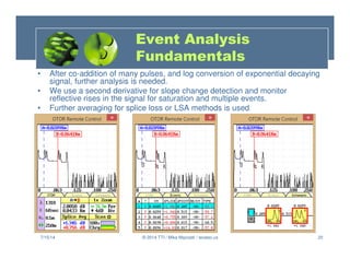
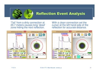
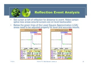
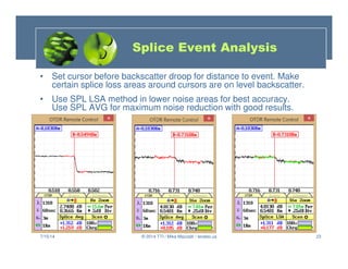
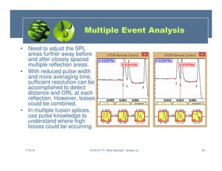
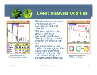
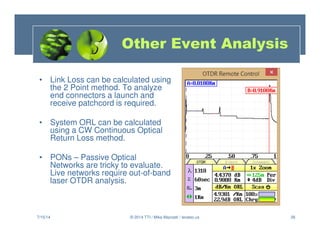
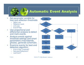
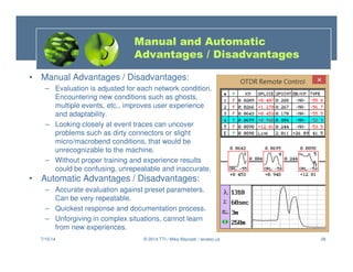
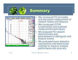

This training presentation introduces OTDR event analysis. It discusses how OTDRs work by launching light pulses into fiber and measuring backscatter. It covers OTDR fundamentals like pulse width, averaging, and signal-to-noise ratio. The presentation teaches how to analyze events like splices and reflections to determine distances, losses, and other issues. Both manual and automatic event analysis techniques are described. The goal is to help users of all experience levels understand OTDR results.


