Class : T.Y.B.Tech Civil
Subject: Water Treatment and distribution
Unit- VI
Treatment of Water
Water Distribution Systems
Prepared by
Dr. V. S. Chaudhari
Professor, Department of Civil Engineering
Sanjivani College of Engineering, Kopargaon, 423603
Mail- chaudharivishalcivil@Sanjivani.org.in,
2.
Distribution of Water
Thewater distribution systems are designed to adequately
satisfy the water requirement for a combination of
domestic, commercial, industrial and fire fighting purpose.
Performance of distribution system can be judged on the
basis of the pressure available in the system for a specific
rate of flow.
The distribution system consists of a network of pipes and
appurtenances, for transporting the water from the
purification plant to the consumers’ taps. It also includes
the design and operation of storage or balancing reservoir.
3.
Good distribution systemshould satisfy
the following Requirement:
• Water quality should not deteriorate in the distribution pipes.
• Every consumer should get sufficient water at the desired
pressure.
• The design and layout should be economical.
• Maintenance should be easy and economical.
• It should be so laid that during repairs, it does not obstruct
traffic.
• All the pipes should be of good quality and leakage through
the joints should be minimum.
• All distribution pipes should be preferably laid one meter
away or above the sewer lines.
4.
Objectives of waterdistribution system
• To convey the water to the point of need from the
treatment plant.
• To preserve water quality after treatment up to
the consumer’s end.
• To ensure sufficient pressure and discharge at all
places during all times.
• It must be capable of meeting the emergency
demand of firefighting.
5.
The water distributionsystem usually accounts
for 40% to 70% of the total cost of the water
supply scheme. Hence, the proper design and
layout of the scheme is of great importance.
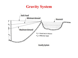
• This gravity-basedwater distribution system eliminates
the need for pumping by utilizing the natural flow from
higher-level sources to lower-level consumers.
• It requires a sufficient elevation difference between
the water source and the localities to maintain an
ample water supply at the doorsteps, considering pipe
losses.
• This method is both cost-effective and dependable
since pumping is completely avoided.
• Cities located in foothill areas with a suitable elevation
difference between their water source and the city can
adopt this system for their water supply.
9.
Continue…
• The gravitationalsystem is designed to allocate only
the minimum permitted available head to the
consumers, with the remaining head being
consumed by frictional and other losses.
• This design minimises leakages and wastage while
reducing the required size of the pipes.
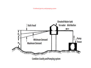
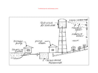
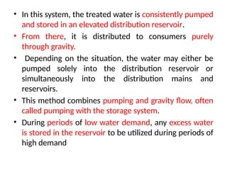
• In thissystem, the treated water is consistently pumped
and stored in an elevated distribution reservoir.
• From there, it is distributed to consumers purely
through gravity.
• Depending on the situation, the water may either be
pumped solely into the distribution reservoir or
simultaneously into the distribution mains and
reservoirs.
• This method combines pumping and gravity flow, often
called pumping with the storage system.
• During periods of low water demand, any excess water
is stored in the reservoir to be utilized during periods of
high demand
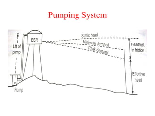
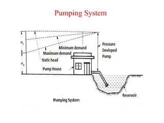
• The pumpingsystem operates by directly pumping the
treated water into the distribution mains without storing
it elsewhere.
• Hence, it is also called a pumping without a storage
system.
• This system requires high-lift pumps that adjust their
speeds to meet the varying water demand.
• As a result, constant monitoring is necessary at the
pumping station to ensure the desired flow in the
distribution system.
• In the event of a power failure, the water supply would
come to a complete halt, which could be disastrous if a
fire were to occur during that time. Due to these
limitations, this method is generally not favoured.
16.
Pressure in theDistribution mains
• Adequate pressure should be available at all points
located even at the remotest spots of the town.
• Desired pressure depends upon :
i)The height to which water is required to be supplied
ii) Whether the supply is metered or not.
iii) Firefighting requirements
iv)Availability of funds
17.
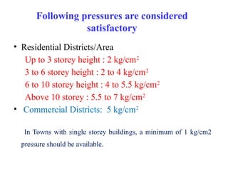
Following pressures areconsidered
satisfactory
• Residential Districts/Area
Up to 3 storey height : 2 kg/cm2
3 to 6 storey height : 2 to 4 kg/cm2
6 to 10 storey height : 4 to 5.5 kg/cm2
Above 10 storey : 5.5 to 7 kg/cm2
• Commercial Districts: 5 kg/cm2
In Towns with single storey buildings, a minimum of 1 kg/cm2
pressure should be available.
18.
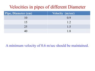
Velocities in pipesof different Diameter
Pipe, Diameter (cm) Velocity (m/sec)
10 0.9
15 1.2
25 1.5
40 1.8
A minimum velocity of 0.6 m/sec should be maintained.
19.
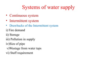
Systems of watersupply
• Continuous system
• Intermittent system
• Drawbacks of the Intermittent system
i) Fire demand
ii) Storage
iii) Pollution in supply
iv)Size of pipe
v)Wastage from water taps
vi) Staff requirement
20.
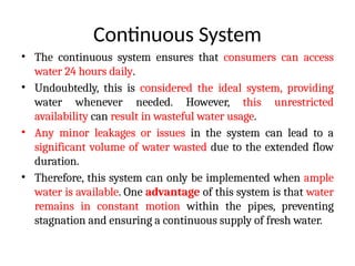
Continuous System
• Thecontinuous system ensures that consumers can access
water 24 hours daily.
• Undoubtedly, this is considered the ideal system, providing
water whenever needed. However, this unrestricted
availability can result in wasteful water usage.
• Any minor leakages or issues in the system can lead to a
significant volume of water wasted due to the extended flow
duration.
• Therefore, this system can only be implemented when ample
water is available. One advantage of this system is that water
remains in constant motion within the pipes, preventing
stagnation and ensuring a continuous supply of fresh water.
21.
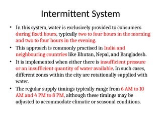
Intermittent System
• Inthis system, water is exclusively provided to consumers
during fixed hours, typically two to four hours in the morning
and two to four hours in the evening.
• This approach is commonly practised in India and
neighbouring countries like Bhutan, Nepal, and Bangladesh.
• It is implemented when either there is insufficient pressure
or an insufficient quantity of water available. In such cases,
different zones within the city are rotationally supplied with
water.
• The regular supply timings typically range from 6 AM to 10
AM and 4 PM to 8 PM, although these timings may be
adjusted to accommodate climatic or seasonal conditions.
22.
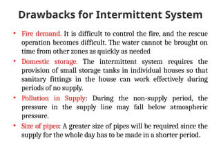
Drawbacks for IntermittentSystem
• Fire demand. It is difficult to control the fire, and the rescue
operation becomes difficult. The water cannot be brought on
time from other zones as quickly as needed
• Domestic storage. The intermittent system requires the
provision of small storage tanks in individual houses so that
sanitary fittings in the house can work effectively during
periods of no supply.
• Pollution in Supply: During the non-supply period, the
pressure in the supply line may fall below atmospheric
pressure.
• Size of pipes: A greater size of pipes will be required since the
supply for the whole day has to be made in a shorter period.
23.
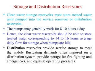
Storage and DistributionReservoirs
• Clear water storage reservoirs must store treated water
until pumped into the service reservoir or distribution
reservoirs.
• The pumps may generally work for 8-10 hours a day.
• Hence, the clear water reservoirs should be able to store
treated water corresponding to 14 to 16 hours average
daily flow for storage when pumps are idle.
• Distribution reservoirs provide service storage to meet
the widely fluctuating demands often imposed on a
distribution system, provide storage for fire fighting and
emergencies, and equalise operating pressures.
24.
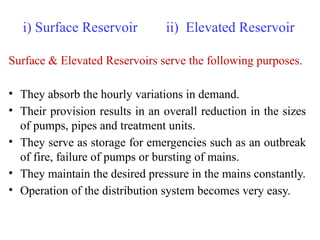
i) Surface Reservoirii) Elevated Reservoir
Surface & Elevated Reservoirs serve the following purposes.
• They absorb the hourly variations in demand.
• Their provision results in an overall reduction in the sizes
of pumps, pipes and treatment units.
• They serve as storage for emergencies such as an outbreak
of fire, failure of pumps or bursting of mains.
• They maintain the desired pressure in the mains constantly.
• Operation of the distribution system becomes very easy.
25.
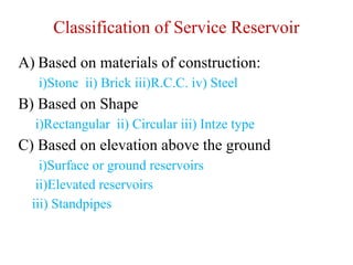
Classification of ServiceReservoir
A) Based on materials of construction:
i)Stone ii) Brick iii)R.C.C. iv) Steel
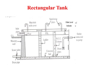
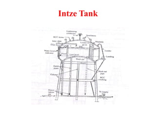
B) Based on Shape
i)Rectangular ii) Circular iii) Intze type
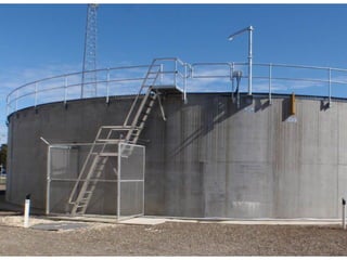
C) Based on elevation above the ground
i)Surface or ground reservoirs
ii)Elevated reservoirs
iii) Standpipes
Layout of DistributionSystems
• Dead End or Tree system
• Grid iron system or Reticulation system
• Circular system or ring system
• Radial system
30.
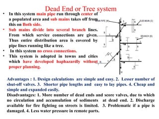
Dead End orTree system
• In this system main pipe run through center of
a populated area and sub mains takes off from
this on Both side.
• Sub mains divide into several branch lines.
From which service connections are given.
Thus entire distribution area is covered by
pipe lines running like a tree.
• In this system no cross connections.
• This system is adopted in towns and cities
which have developed haphazardly without
proper planning.
Advantages : 1. Design calculations are simple and easy. 2. Lesser number of
shut-off valves. 3. Shorter pipe lengths and easy to lay pipes. 4. Cheap and
simple and expanded easily.
Disadvantages: 1. More number of dead ends and score valves, due to which
no circulation and accumulation of sediments at dead end. 2. Discharge
available for fire fighting on streets is limited. 3. Problematic if a pipe is
damaged. 4. Less water pressure in remote parts.
31.
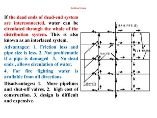
Gridiron System
If thedead ends of dead-end system
are interconnected, water can be
circulated through the whole of the
distribution system. This is also
known as an interlaced system.
Advantages: 1. Friction loss and
pipe size is less. 2. Not problematic
if a pipe is damaged 3. No dead
ends , allows circulation of water.
4. For fire fighting water is
available from all directions.
Disadvantages: 1. More pipelines
and shut-off valves. 2. high cost of
construction. 3. design is difficult
and expensive.
32.
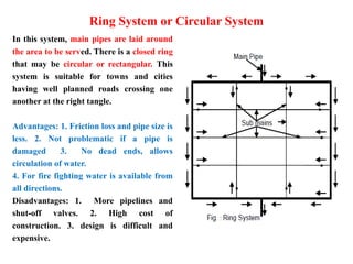
Ring System orCircular System
In this system, main pipes are laid around
the area to be served. There is a closed ring
that may be circular or rectangular. This
system is suitable for towns and cities
having well planned roads crossing one
another at the right tangle.
Advantages: 1. Friction loss and pipe size is
less. 2. Not problematic if a pipe is
damaged 3. No dead ends, allows
circulation of water.
4. For fire fighting water is available from
all directions.
Disadvantages: 1. More pipelines and
shut-off valves. 2. High cost of
construction. 3. design is difficult and
expensive.
33.
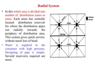
Radial System
• Inthis whole area is divided into
number of distribution zones or
areas. Each areas has centrally
located distribution reservoir
fro where the distribution pipes
run radially towards the
periphery of distribution area.
This system gives quick service,
without much loss of head.
• Water is supplied to the
consumer with high pressure.
Designing of pipe is simple.
Several reservoirs required are
more.
34.
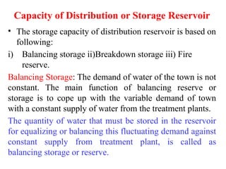
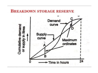
Capacity of Distributionor Storage Reservoir
• The storage capacity of distribution reservoir is based on
following:
i) Balancing storage ii)Breakdown storage iii) Fire
reserve.
Balancing Storage: The demand of water of the town is not
constant. The main function of balancing reserve or
storage is to cope up with the variable demand of town
with a constant supply of water from the treatment plants.
The quantity of water that must be stored in the reservoir
for equalizing or balancing this fluctuating demand against
constant supply from treatment plant, is called as
balancing storage or reserve.
35.
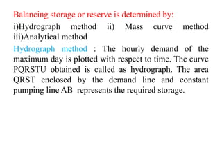
Balancing storage orreserve is determined by:
i)Hydrograph method ii) Mass curve method
iii)Analytical method
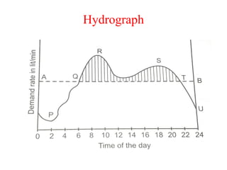
Hydrograph method : The hourly demand of the
maximum day is plotted with respect to time. The curve
PQRSTU obtained is called as hydrograph. The area
QRST enclosed by the demand line and constant
pumping line AB represents the required storage.
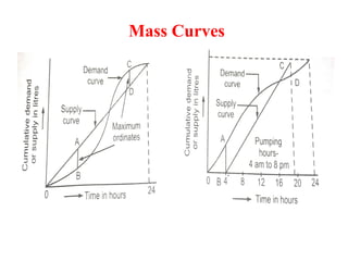
Mass curve method
•Mass curve is the graph of cumulative demand (out flow) versus
time OR cumulative supply (inflow) versus Time. Mass curve of
demand and mass curve of supply are plotted on the same graph
paper. The balancing capacity is then worked out by adding the
maximum ordinates between the demand curve and supply curve
as explained below:
1.For the maximum demand day, obtain hourly demand for 24 hours.
2. Workout cumulative demand starting from a fixed time like 8.0 am
or 12.0 am night etc.
3. Plot the graph of cumulative demand against time to get a mass
curve of demand.
4. On the same graph plot the cumulative supply against time.
5. Find the maximum ordinates between the two curves.
6. The sum of the two max ordinates is the required balancing
storage.
• Plumbing andsanitary fittings: You must have seen
plumbing and sanitary fittings and fixtures installed
in the kitchen, bathroom or toilets of your home,
school or other buildings.
• A plumbing fixture is a part that is connected to a
plumbing system and carries water through a
building.
• The most common plumbing fixtures are bathtubs,
sinks, showers, tubs, toilets and outlets.
• While a fixture can be fixed into walls or the floor, a
fitting is an item that can be hung by a hook, screw or
nail.
41.
• For abuilding, the plumbing system should be
designed in a way that water is distributed uniformly,
throughout the day.
• It should be ensured that a combination of fittings and
fixtures is selected in such a way that uniform supply
of water and discharge of water is maintained.
42.
• Various typesof pipe fitting are available in plumbing
systems for different purposes and functions.
• A pipe fitting is used in the plumbing system to join
multiple pipes of same size or different sizes, to
regulate the flow or to measure the flow.
• They are made, up of different materials like copper,
iron, brass, PVC, etc.
• There are many different kinds of fittings, made from
a variety of materials.
43.
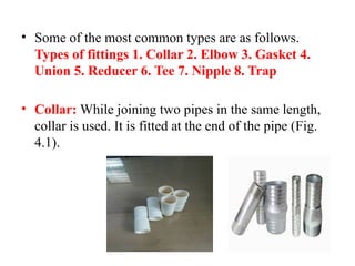
• Some ofthe most common types are as follows.
Types of fittings 1. Collar 2. Elbow 3. Gasket 4.
Union 5. Reducer 6. Tee 7. Nipple 8. Trap
• Collar: While joining two pipes in the same length,
collar is used. It is fitted at the end of the pipe (Fig.
4.1).
44.
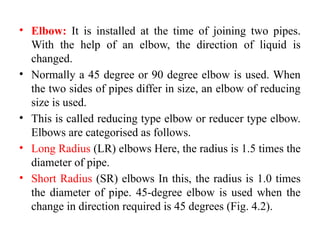
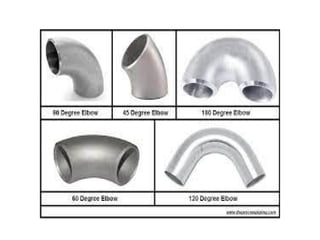
• Elbow: Itis installed at the time of joining two pipes.
With the help of an elbow, the direction of liquid is
changed.
• Normally a 45 degree or 90 degree elbow is used. When
the two sides of pipes differ in size, an elbow of reducing
size is used.
• This is called reducing type elbow or reducer type elbow.
Elbows are categorised as follows.
• Long Radius (LR) elbows Here, the radius is 1.5 times the
diameter of pipe.
• Short Radius (SR) elbows In this, the radius is 1.0 times
the diameter of pipe. 45-degree elbow is used when the
change in direction required is 45 degrees (Fig. 4.2).
46.
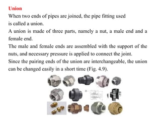
Union
When two endsof pipes are joined, the pipe fitting used
is called a union.
A union is made of three parts, namely a nut, a male end and a
female end.
The male and female ends are assembled with the support of the
nuts, and necessary pressure is applied to connect the joint.
Since the pairing ends of the union are interchangeable, the union
can be changed easily in a short time (Fig. 4.9).
47.
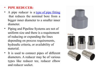
• PIPE REDUCER:
•A pipe reducer is a type of pipe fitting
that reduces the nominal bore from a
bigger inner diameter to a smaller inner
diameter.
• Piping and Pipeline Systems are not of
uniform size and there is a requirement
of reducing or expanding the lines
depending on process requirements,
hydraulic criteria, or availability of
material.
• It is used to connect pipes of different
diameters. A reducer may be of various
types like reducer tee, reducer elbow
and reducer socket.
48.
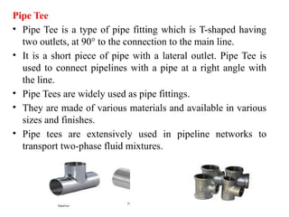
Pipe Tee
• PipeTee is a type of pipe fitting which is T-shaped having
two outlets, at 90° to the connection to the main line.
• It is a short piece of pipe with a lateral outlet. Pipe Tee is
used to connect pipelines with a pipe at a right angle with
the line.
• Pipe Tees are widely used as pipe fittings.
• They are made of various materials and available in various
sizes and finishes.
• Pipe tees are extensively used in pipeline networks to
transport two-phase fluid mixtures.
49.
• SMART CITIESMISSION IN INDIA
• Vision
• With an increase in urban population and rapid expansion of
areas, government is looking at smarter ways to manage
complexities, increase efficiencies and improve quality of life.
This has created a need for cities that monitor and integrate
infrastructure to better optimise resources and maximise
services to citizens.
• Objective
• The objective of the smart city initiative is to promote
sustainable and inclusive cities that provide core infrastructure
to give a decent quality of life, a clean and sustainable
environment through application of some smart solutions such
as data-driven traffic management, intelligent lighting
systems, etc
50.
• The coreinfrastructure elements in a Smart City
include:
i. adequate water supply,
ii. assured electricity supply,
iii. sanitation, including solid waste management,
iv. efficient urban mobility and public transport,
v. affordable housing, especially for the poor,
vi. robust IT connectivity and digitalization,
vii. good governance, especially e-Governance and citizen
participation,
viii. sustainable environment,
ix. safety and security of citizens, particularly women,
children and the elderly, and
x. health and education.
52.
• Jal JeevanMission (JJM): The Central Government’s assistance to
States for rural water supply began in 1972 with the launch of the
Accelerated Rural Water Supply Programme.
• It was renamed as National Rural Drinking Water Programme
(NRDWP) in 2009, which is a centrally sponsored scheme with fund
sharing between the Centre and the States.
• Under NRDWP, one of the objectives was to “enable all households to
have access to and use safe & adequate drinking water within premises
to the extent possible”.
• It was proposed to achieve the goal by 2030, coinciding with the
United Nation’s Sustainable Development Goals.
• But now, it is has been planned to achieve the goal by 2024 through Jal
Jeevan Mission (JJM).
• As per the information available with DDWS, as on 31.3.2019, only
18.33% of rural households i.e., 3.27 Crore out of the total 17.87 Crore
rural households in the country, have piped water connection.
53.
• Jal JeevanMission (JJM) Government of India has restructured and subsumed
the ongoing National Rural Drinking Water Programme(NRDWP) into Jal
Jeevan Mission (JJM) to provide Functional Household Tap Connection
(FHTC) to every rural household i.e., Har Ghar Nal Se Jal (HGNSJ).
• The following kinds of works/ schemes are proposed to be taken up under JJM:
i.) In-village water supply (PWS) infrastructure for tap water connection to
every household;
• ii.) Reliable drinking water source development/ augmentation of existing
sources;
• iii.) Transfer of water (multi-village scheme; where quantity & quality issues
are there in the local water sources);
• iv.) Technological intervention for treatment to make water potable (where
water quality is an issue, but quantity is sufficient);
• v.) Retrofitting of completed and ongoing piped water supply schemes to
provide FHTC and raise the service level;
• vi.) Grey water management; vii.) Capacity building of various stakeholders
and support activities to facilitate the implementation.


![Microsoft power point distribution systems [read-only]](https://cdn.slidesharecdn.com/ss_thumbnails/diwiuehtrycy7ayewpb3-signature-7f20760b9f97167ae74c1ef33fe58a16817ef3afaab94a37d2a9dfe6de74b684-poli-150822072504-lva1-app6892-thumbnail.jpg?width=640&height=640&fit=bounds)


