This document provides an overview of general considerations for designing a water distribution system. It discusses 12 key factors to consider:
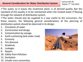
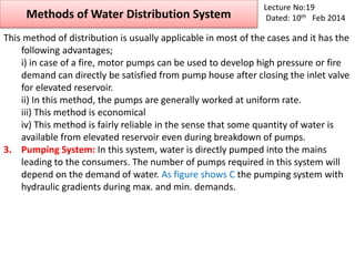
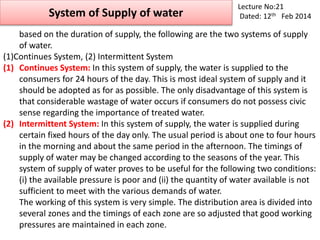
1. Circulation of water in the system to avoid dead ends.
2. Ensuring the construction and design allows sufficient water supply at all times and desired pressures.
3. Preventing contamination from sewage by proper separation of water and sewer pipes.
4. Providing adequate earth cushioning over main pipes laid under roads.
5. Designing the system economically by considering factors like pumping heads and pipe diameters.
6. Ensuring adequate water supply for fire demands.
7. Setting proper pipe gradients based on ground contours and hydraulic gradients.


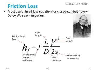
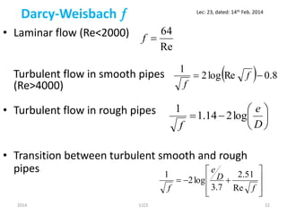
![Darcy-Weisbach
• Most recent development of Darcy Weisbach coefficient -
Explicit equation [Swamee and Jain, 1976] applicable to
entire turbulent flow regime (smooth, transition and rough
pipes):
2
9.0
Re
74.5
7.3
log
25.0
D
e
f
2014 11CE 25
Lec: 23, dated: 14th Feb. 2014](https://image.slidesharecdn.com/environmenti-lecs18to23wbb34-160126125916/85/Environment-i-lecs-18-to-23-wbb34-25-320.jpg)