This document discusses various input/output devices and communication protocols used for connecting devices in embedded systems. It describes synchronous and asynchronous serial communication, defining characteristics of each. Common internal and external serial interfaces like SPI, UART, and RS-232 are explained. The document also covers parallel ports, handshaking signals, and protocols for device networking like HDLC and TCP/IP. Overall it provides an overview of the devices and communication methods used to connect multiple devices in embedded systems.
Contents
1. Input OutputDevices
2. Timer & Counting Devices
3. Serial Communication using ‘I2C’,‘CAN’ &
Advanced Input Output buses between the
Networked Multiple Devices
4. Host system or Computer Parallel
Communication between the Networked
Input Output multiple devices using ISA, PCI,
PCI-X and Advanced Buses
3.
Input Output Devices
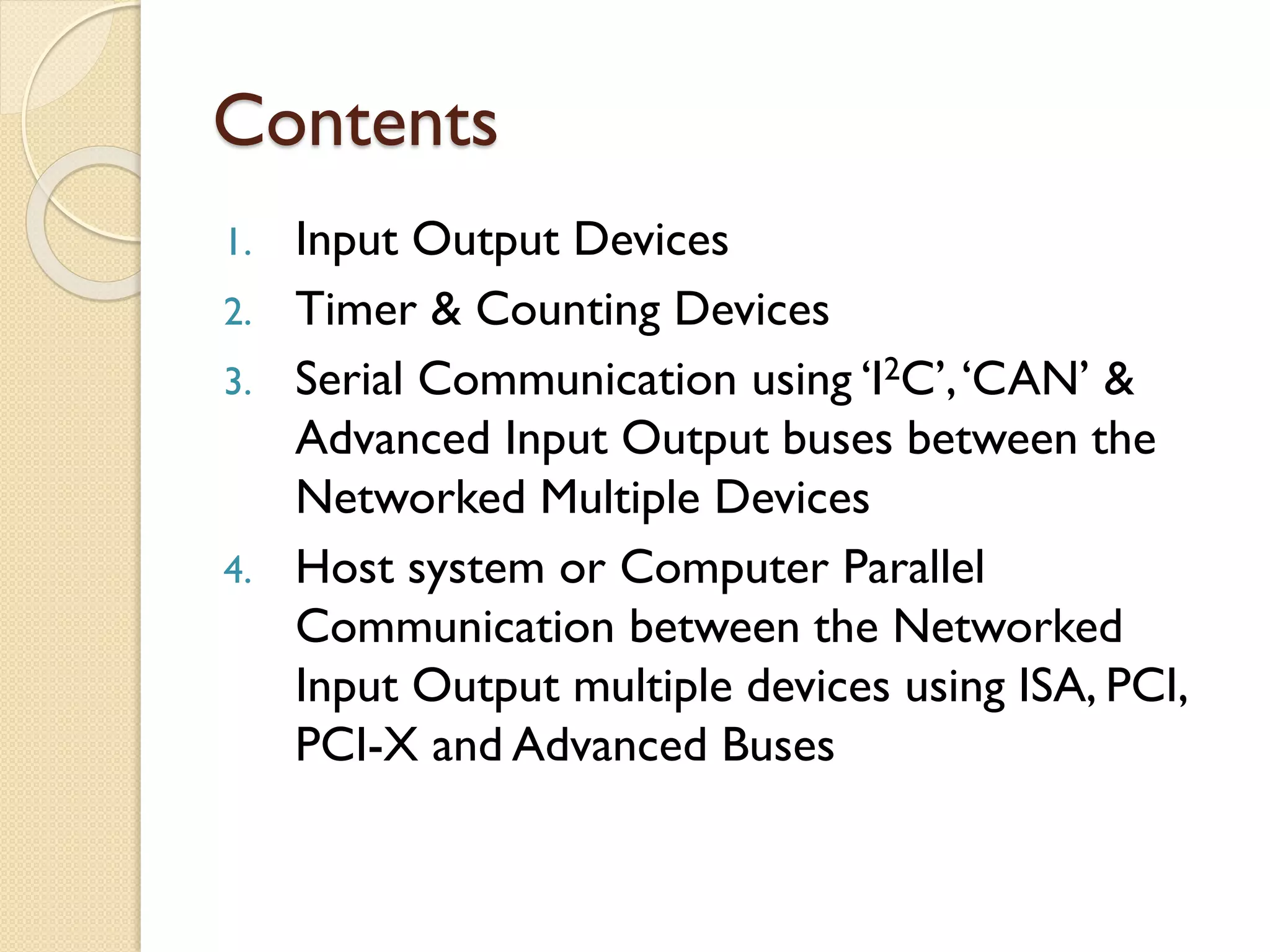
I/O devices can be classified into following
I/O types:
◦ i) Synchronous Serial Input
◦ ii) Synchronous Serial Output
◦ iii) Asynchronous Serial UART Input
◦ iv) Asynchronous Serial UART Output
◦ v) Parallel one bit Input
◦ vi) Parallel one bit Output
◦ vii) Parallel Port Input
◦ viii) Parallel Port Output
◦ Some devices function both as input & as output,
example - MODEM
4.
Port
A PORT isa device
◦ to receive the bytes from external peripheral(s)
for reading them later using instructions
executed on the processor or
◦ to send the bytes to external peripheral or
device or processor using instructions executed
on processor
A Port connects to the processor using
address decoder and system buses
The processor uses the addresses of the
port-registers for programming the port
functions or modes, reading port status and
for writing or reading bytes.
5.
Examples ofVarious typesof I/O devices
Synchronous
Serial Input
Inter-processor data transfer, reading from CD or hard disk, audio
input, video input, dial tone, network input, transceiver input, scanner
input, remote controller input, serial I/O bus input, writing to flash
memory using SDIO (Secure Data Association IO based card)
Synchronous
Serial Output
Inter-processor data transfer, multiprocessor communication, writing to
CD or hard disk, audio Input/output, video Input/output, dialler output,
network device output, remoteTV Control, transceiver output, and serial
I/O bus output or writing to flash memory using SDIO
Serial
Asynchronous
UART Input
Keypad controller serial data-in, mice, keyboard controller, modem
input, character send inputs on serial line [also called UART (universal
receiverand transmitter) input when according to UART mode]
Serial
Asynchronous
UART Output
Output from modem, output for printer, the output on a serial line
[also called UART output when according to UART]
I/O DeviceType Examples
6.
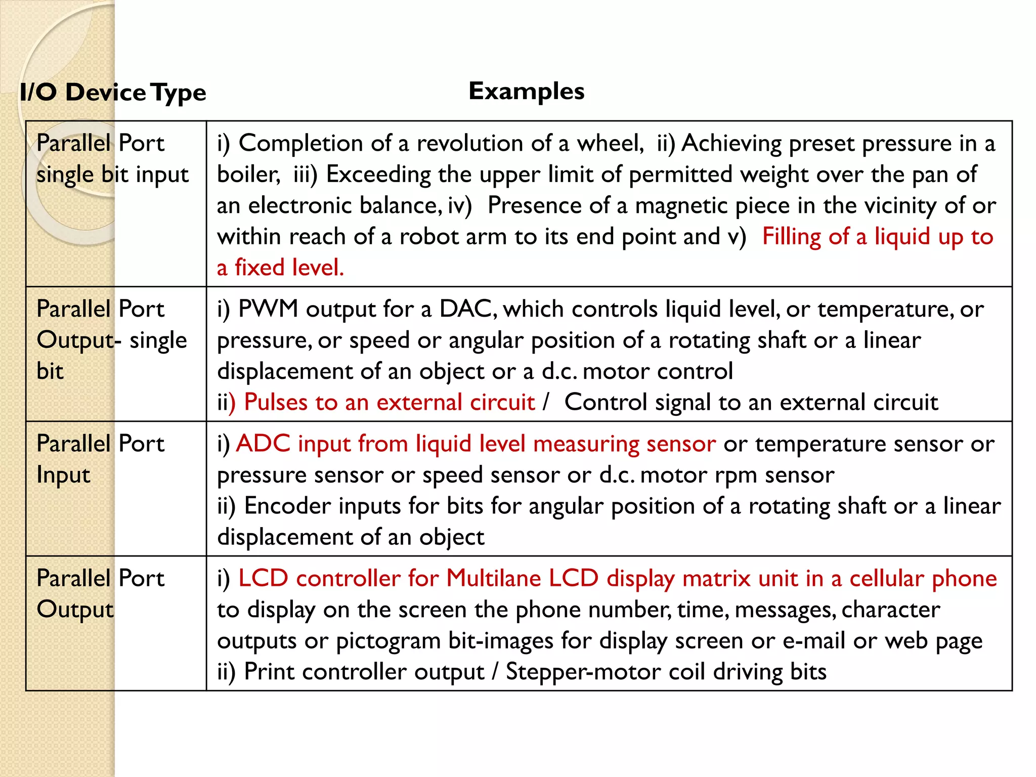
Parallel Port
single bitinput
i) Completion of a revolution of a wheel, ii) Achieving preset pressure in a
boiler, iii) Exceeding the upper limit of permitted weight over the pan of
an electronic balance, iv) Presence of a magnetic piece in the vicinity of or
within reach of a robot arm to its end point and v) Filling of a liquid up to
a fixed level.
Parallel Port
Output- single
bit
i) PWM output for a DAC, which controls liquid level, or temperature, or
pressure, or speed or angular position of a rotating shaft or a linear
displacement of an object or a d.c. motor control
ii) Pulses to an external circuit / Control signal to an external circuit
Parallel Port
Input
i) ADC input from liquid level measuring sensor or temperature sensor or
pressure sensor or speed sensor or d.c. motor rpm sensor
ii) Encoder inputs for bits for angular position of a rotating shaft or a linear
displacement of an object
Parallel Port
Output
i) LCD controller for Multilane LCD display matrix unit in a cellular phone
to display on the screen the phone number, time, messages, character
outputs or pictogram bit-images for display screen or e-mail or web page
ii) Print controller output / Stepper-motor coil driving bits
I/O DeviceType Examples
7.
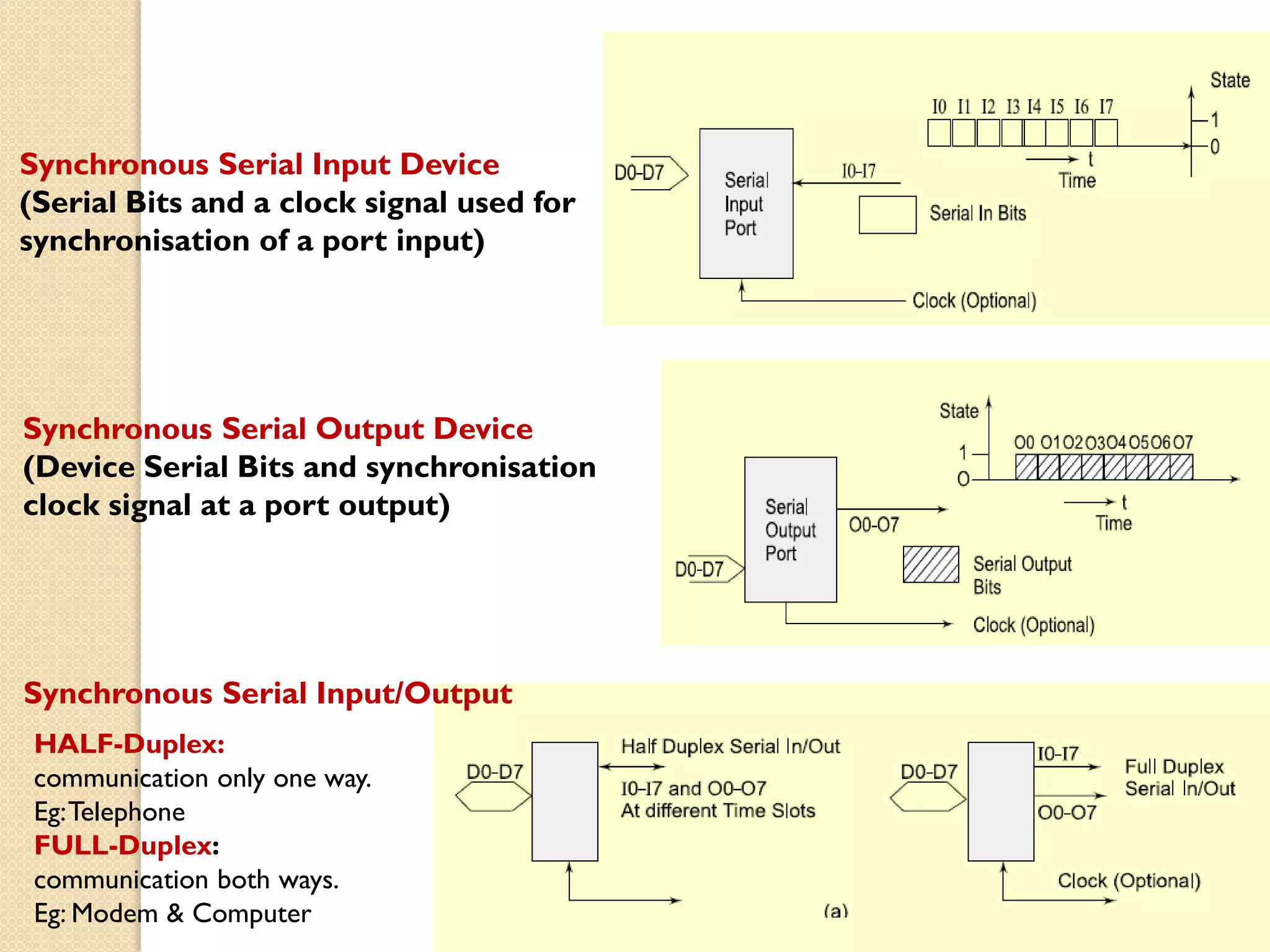
Synchronous Serial InputDevice
(Serial Bits and a clock signal used for
synchronisation of a port input)
Synchronous Serial Output Device
(Device Serial Bits and synchronisation
clock signal at a port output)
Synchronous Serial Input/Output
HALF-Duplex:
communication only one way.
Eg:Telephone
FULL-Duplex:
communication both ways.
Eg: Modem & Computer
8.
Synchronous Serial Input:
•Thesender along with the serial bits also sends the clock pulses SCLK (serial clock) to
the receiver port pin.The port synchronizes the serial data input bits with clock bits.
•The bytes are received at constant rates. Each byte at input port separates by 8T and data
transfer rate for the serial line bits is (1/T) bps. [1bps = 1 bit per s]
Synchronous Serial Output:
• Each bit in each byte sent in synchronization with a clock.
• Bytes sent at constant rates. If clock period =T, then data transfer rate is (1/T) bps.
Synchronous Serial Input / Output :
• Each bit in each byte is in synchronization at input and each bit in each byte is in
synchronization at output with the master clock output .
•The bytes are sent or received at constant rates.
Asynchronous Serial input:
• Does not receive the clock pulses or clock information along with the bits.
• Each bit is received in each byte at fixed intervals but each received byte is not in
synchronization.
• Bytes separate by the variable intervals or phase differences
• Asynchronous serial input also called UART input if serial input is according to UART
protocol
9.
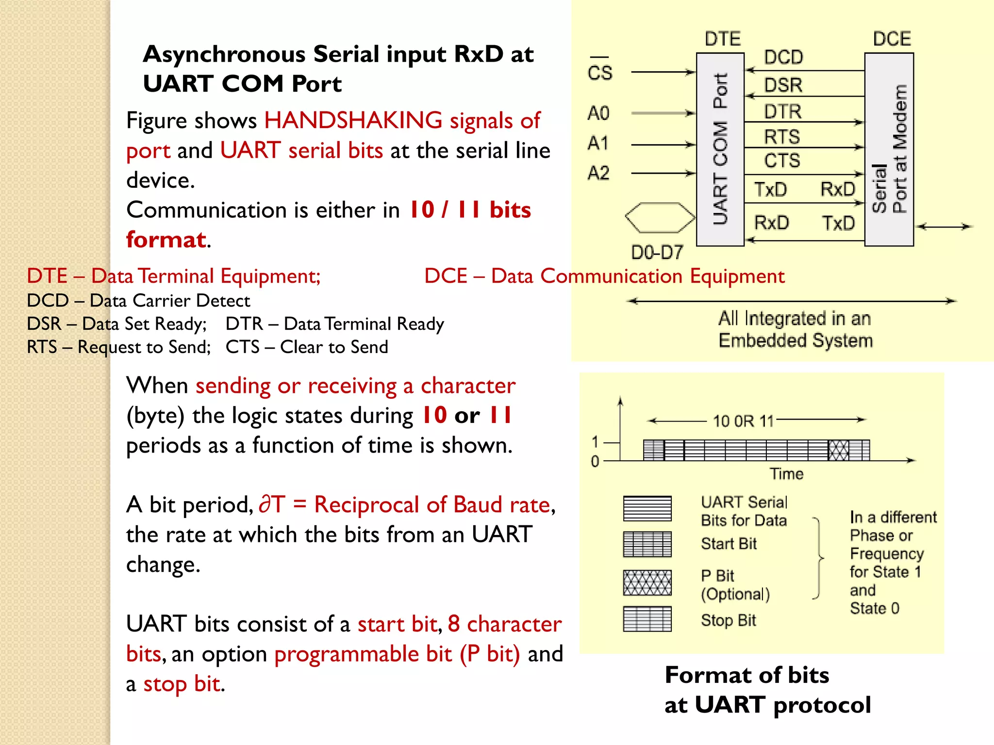
Asynchronous Serial inputRxD at
UART COM Port
Format of bits
at UART protocol
Figure shows HANDSHAKING signals of
port and UART serial bits at the serial line
device.
Communication is either in 10 / 11 bits
format.
When sending or receiving a character
(byte) the logic states during 10 or 11
periods as a function of time is shown.
A bit period, ∂T = Reciprocal of Baud rate,
the rate at which the bits from an UART
change.
UART bits consist of a start bit, 8 character
bits, an option programmable bit (P bit) and
a stop bit.
DTE – Data Terminal Equipment; DCE – Data Communication Equipment
DCD – Data Carrier Detect
DSR – Data Set Ready; DTR – DataTerminal Ready
RTS – Request to Send; CTS – Clear to Send
10.
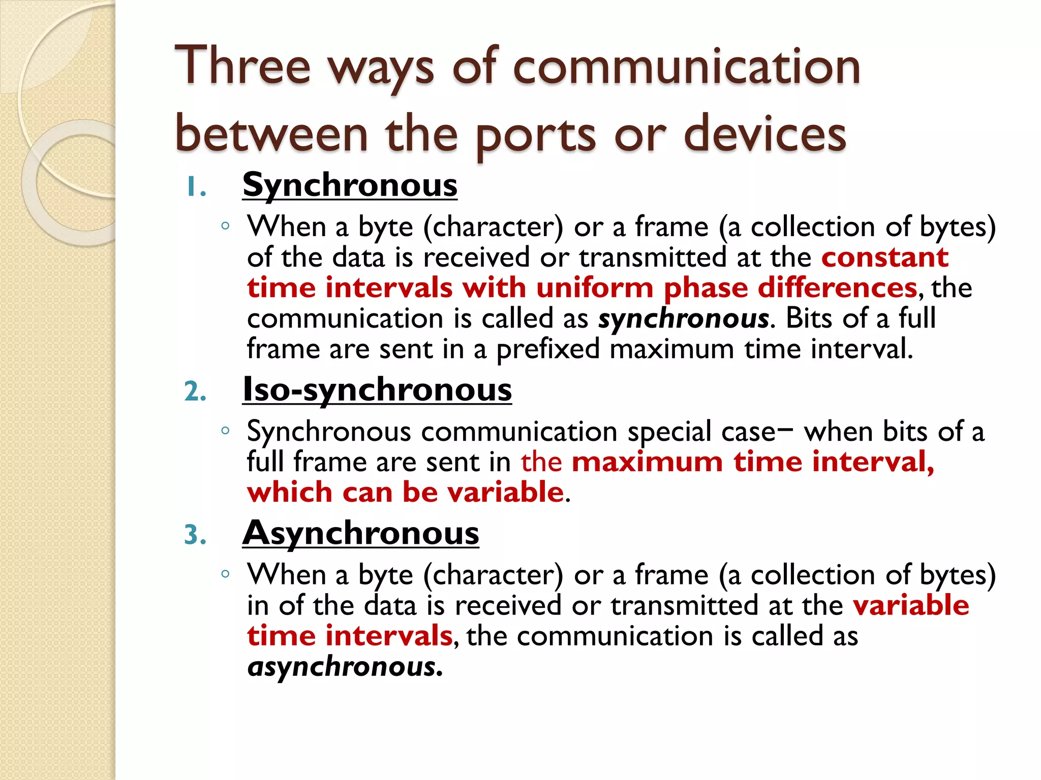
Three ways ofcommunication
between the ports or devices
1. Synchronous
◦ When a byte (character) or a frame (a collection of bytes)
of the data is received or transmitted at the constant
time intervals with uniform phase differences, the
communication is called as synchronous. Bits of a full
frame are sent in a prefixed maximum time interval.
2. Iso-synchronous
◦ Synchronous communication special case− when bits of a
full frame are sent in the maximum time interval,
which can be variable.
3. Asynchronous
◦ When a byte (character) or a frame (a collection of bytes)
in of the data is received or transmitted at the variable
time intervals, the communication is called as
asynchronous.
11.
Characteristics of
Synchronous communication
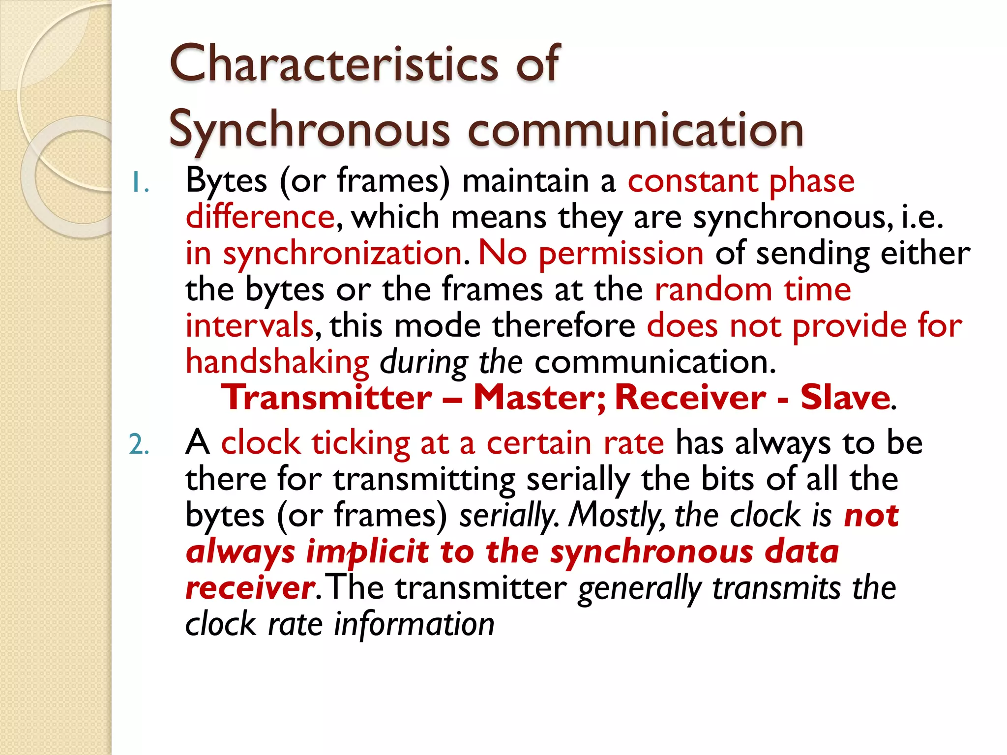
1.Bytes (or frames) maintain a constant phase
difference, which means they are synchronous, i.e.
in synchronization. No permission of sending either
the bytes or the frames at the random time
intervals, this mode therefore does not provide for
handshaking during the communication.
Transmitter – Master; Receiver - Slave.
2. A clock ticking at a certain rate has always to be
there for transmitting serially the bits of all the
bytes (or frames) serially. Mostly, the clock is not
always implicit to the synchronous data
receiver.The transmitter generally transmits the
clock rate information
12.
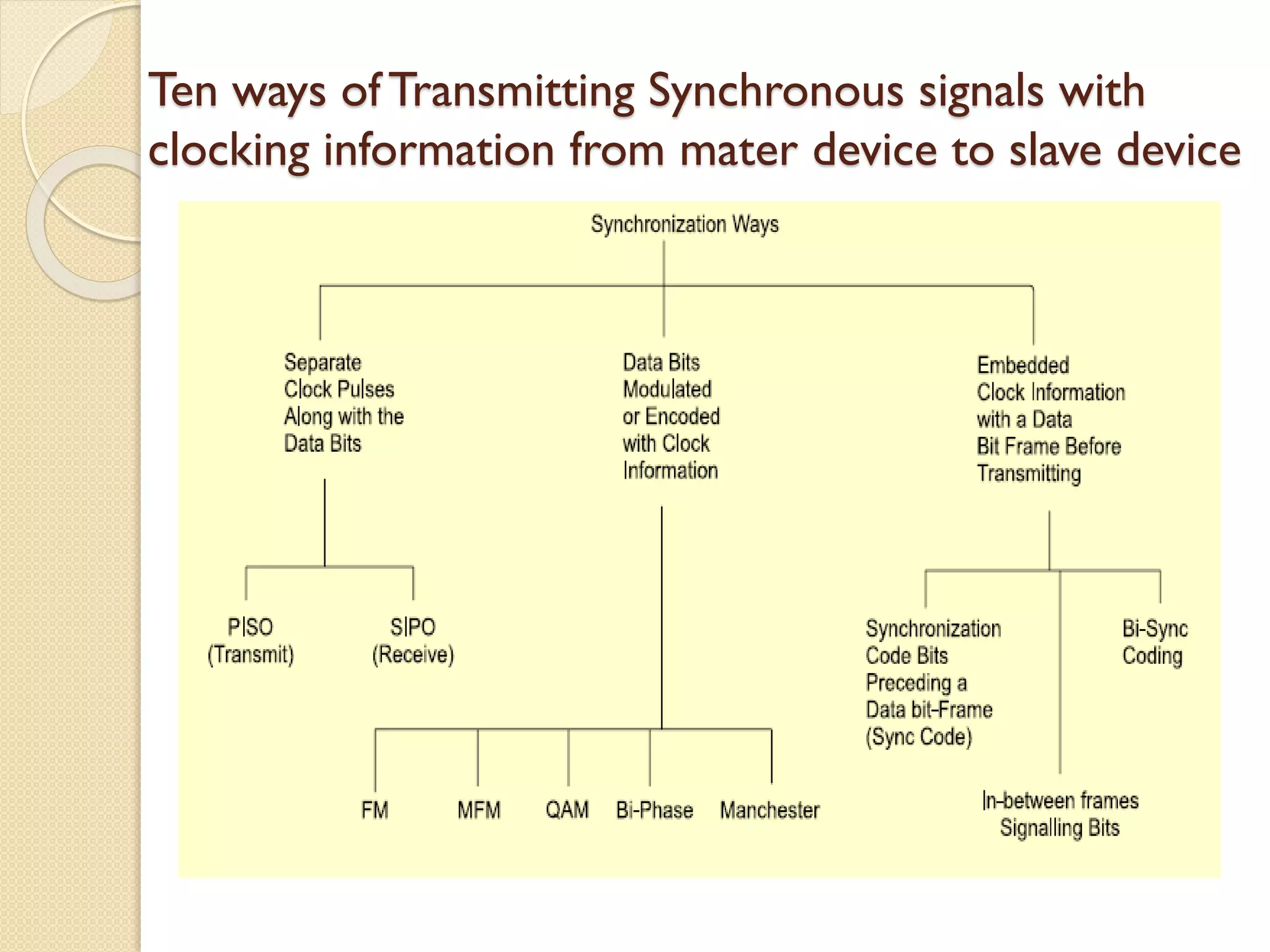
Ten ways ofTransmitting Synchronous signals with
clocking information from mater device to slave device
13.
Synchronous Communication
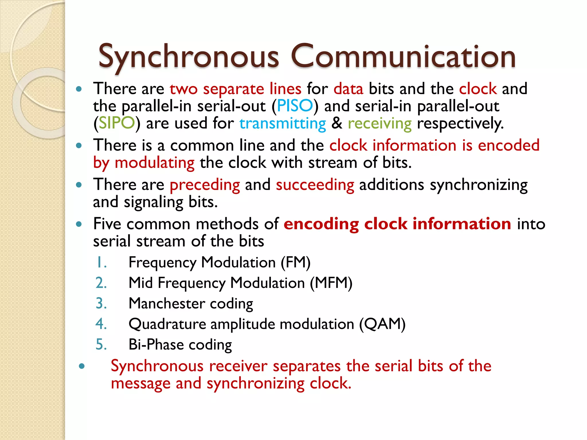
Thereare two separate lines for data bits and the clock and
the parallel-in serial-out (PISO) and serial-in parallel-out
(SIPO) are used for transmitting & receiving respectively.
There is a common line and the clock information is encoded
by modulating the clock with stream of bits.
There are preceding and succeeding additions synchronizing
and signaling bits.
Five common methods of encoding clock information into
serial stream of the bits
1. Frequency Modulation (FM)
2. Mid Frequency Modulation (MFM)
3. Manchester coding
4. Quadrature amplitude modulation (QAM)
5. Bi-Phase coding
Synchronous receiver separates the serial bits of the
message and synchronizing clock.
14.
Asynchronous Communication
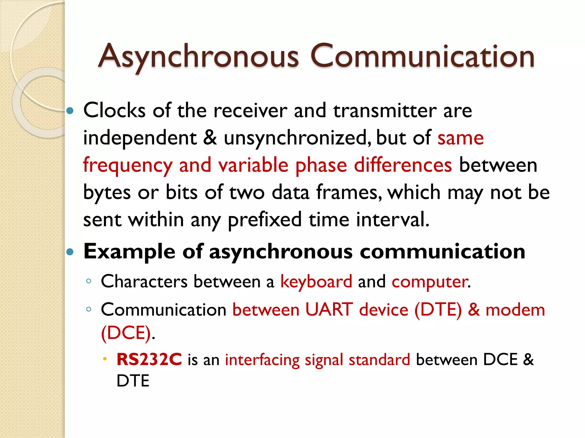
Clocksof the receiver and transmitter are
independent & unsynchronized, but of same
frequency and variable phase differences between
bytes or bits of two data frames, which may not be
sent within any prefixed time interval.
Example of asynchronous communication
◦ Characters between a keyboard and computer.
◦ Communication between UART device (DTE) & modem
(DCE).
RS232C is an interfacing signal standard between DCE &
DTE
15.
Characteristics of
Asynchronous communication
1.Bytes (or frames) need not maintain a constant
phase difference and are asynchronous, i.e., not in
synchronization.There is permission to send
either bytes or frames at variable time intervals─
This facilitates in-between handshaking between
the serial transmitter port and serial receiver port
2. Though the clock must ticking at a certain rate
always has to be there to transmit the bits of a
single byte (or frame) serially, it is always
implicit to the asynchronous data receiver and
is independent of the transmitter
16.
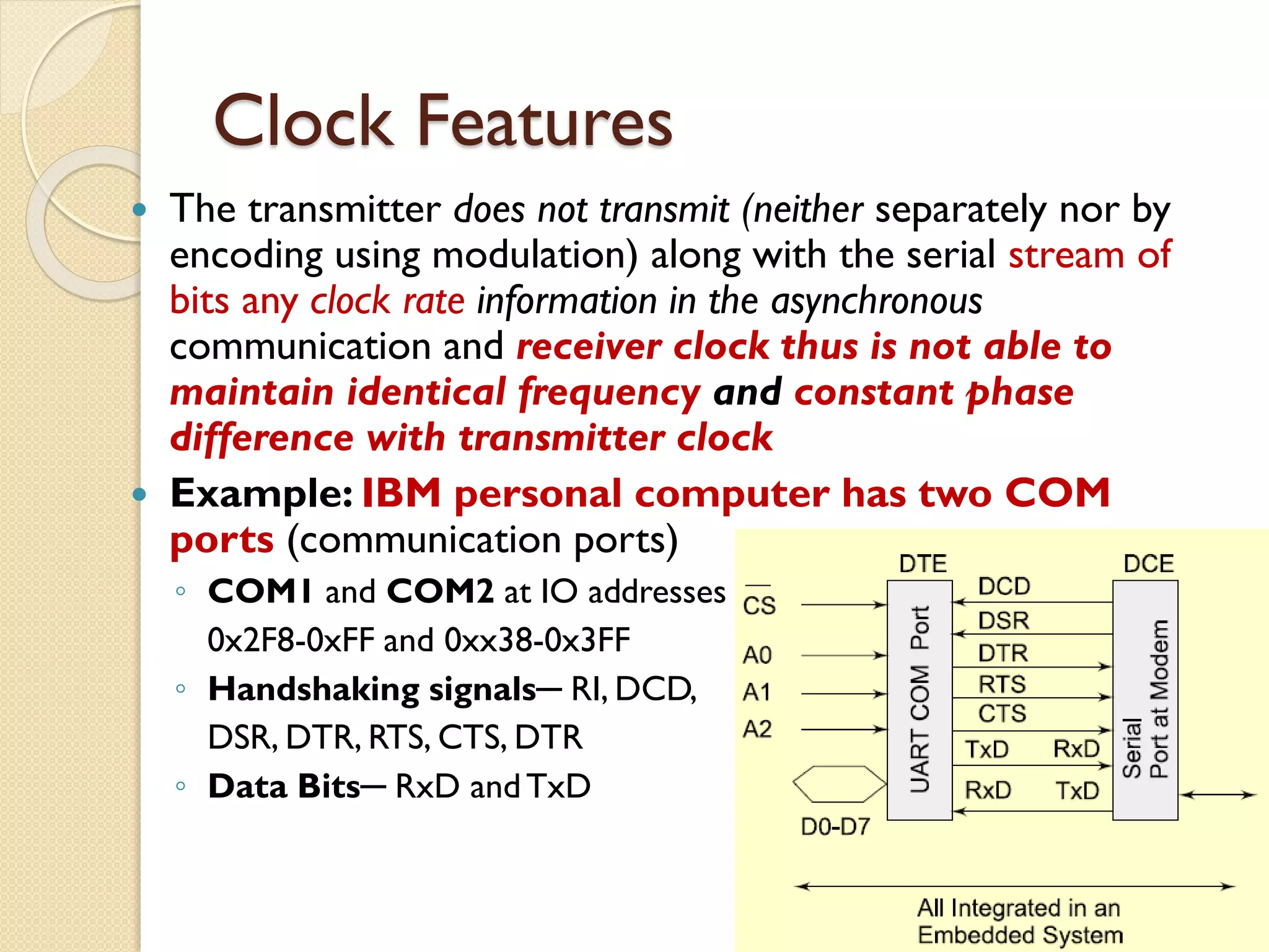
Clock Features
Thetransmitter does not transmit (neither separately nor by
encoding using modulation) along with the serial stream of
bits any clock rate information in the asynchronous
communication and receiver clock thus is not able to
maintain identical frequency and constant phase
difference with transmitter clock
Example: IBM personal computer has two COM
ports (communication ports)
◦ COM1 and COM2 at IO addresses
0x2F8-0xFF and 0xx38-0x3FF
◦ Handshaking signals─ RI, DCD,
DSR, DTR, RTS, CTS, DTR
◦ Data Bits─ RxD andTxD
17.
Example: COM portand Modem
Handshaking signals
When a modem connects, modem sends data carrier detect
DCD signal at an instance t0.
Communicates data set ready (DSR) signal at an instance t1
when it receives the bytes on the line.
Receiving computer (terminal) responds at an instance t2 by
data terminal ready (DTR) signal.
After DTR, request to send (RTS) signal is sent at an instance t3
Receiving end responds by clear to send (CTS) signal at an
instance t4.After the response CTS, the data bits are
transmitted by modem from an instance t5 to the receiver
terminal.
Between two sets of bytes sent in asynchronous mode, the
handshaking signals RTS and CTS can again be exchanged.
This explains why the bytes do not remain synchronized
during asynchronous transmission.
18.
Communication Protocols
Aprotocol is a standard adopted, which
tells the way in which the bits of a frame
must be sent from a device (or controller
or port or processor) to another device
or system.
[Even in personal communication we
follow a protocol – we say Hello!Then
talk and then say good bye!]
19.
Protocols
For synchronouscommunication – HDLC (High
Level Data Link Control), Frame Relay
For asynchronous transmission from a device
port− RS232C, UART, X.25,ATM, DSL and
ADSL
For networking the physical devices in
telecommunication and computer networks −
Ethernet and token ring protocols used in LAN
networks
Internet appliances application protocols andWeb
protocols ─HTTP (hyper text transfer
protocol), HTTPS (hyper text transfer protocol
Secure Socket Layer), SMTP (Simple Mail Transfer
Protocol)
20.
File transfer, BootProtocols in embedded
devices network
TELNET (Tele network),
FTP (file transfer protocol),
DNS (domain network server),
IMAP 4 (Internet Message Exchange
Application Protocol) and
Bootp (Bootstrap protocol).
Wireless Protocols in embedded devices
network
– WLAN 802.11, 802.16, Bluetooth, ZigBee,
WiFi,WiMax
21.
Exemplary Protocol –HDLC
HDLC (High-level Data Link Control) is an
International standard protocol for the data
link network.
Used for linking data from point to point &
between multiple points, it’s bit oriented
protocol.
For synchronous communication between
two data link layers on a network.
There are two formats Standard HDLC and
Extended HDLC for 28 and 216 destination
devices or systems, respectively .
22.
Exemplary Protocol –RS232C
• For asynchronous communication
between two data serial links on a
network ─ Between a data
communication equipment (DCE) and
data terminal equipment (DTE)
RS232C ─ a standard protocol used in
IBM PC COM ports, keyboard, computer-
mice and
For the data serial link network in UART
bit format
23.
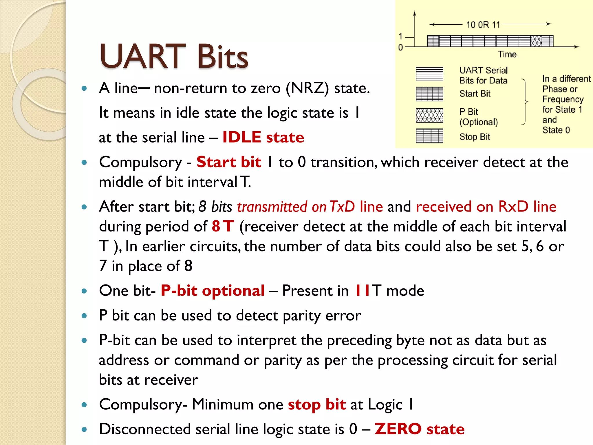
UART Bits
Aline─ non-return to zero (NRZ) state.
It means in idle state the logic state is 1
at the serial line – IDLE state
Compulsory - Start bit 1 to 0 transition, which receiver detect at the
middle of bit intervalT.
After start bit; 8 bits transmitted onTxD line and received on RxD line
during period of 8T (receiver detect at the middle of each bit interval
T ), In earlier circuits, the number of data bits could also be set 5, 6 or
7 in place of 8
One bit- P-bit optional – Present in 11T mode
P bit can be used to detect parity error
P-bit can be used to interpret the preceding byte not as data but as
address or command or parity as per the processing circuit for serial
bits at receiver
Compulsory- Minimum one stop bit at Logic 1
Disconnected serial line logic state is 0 – ZERO state
24.
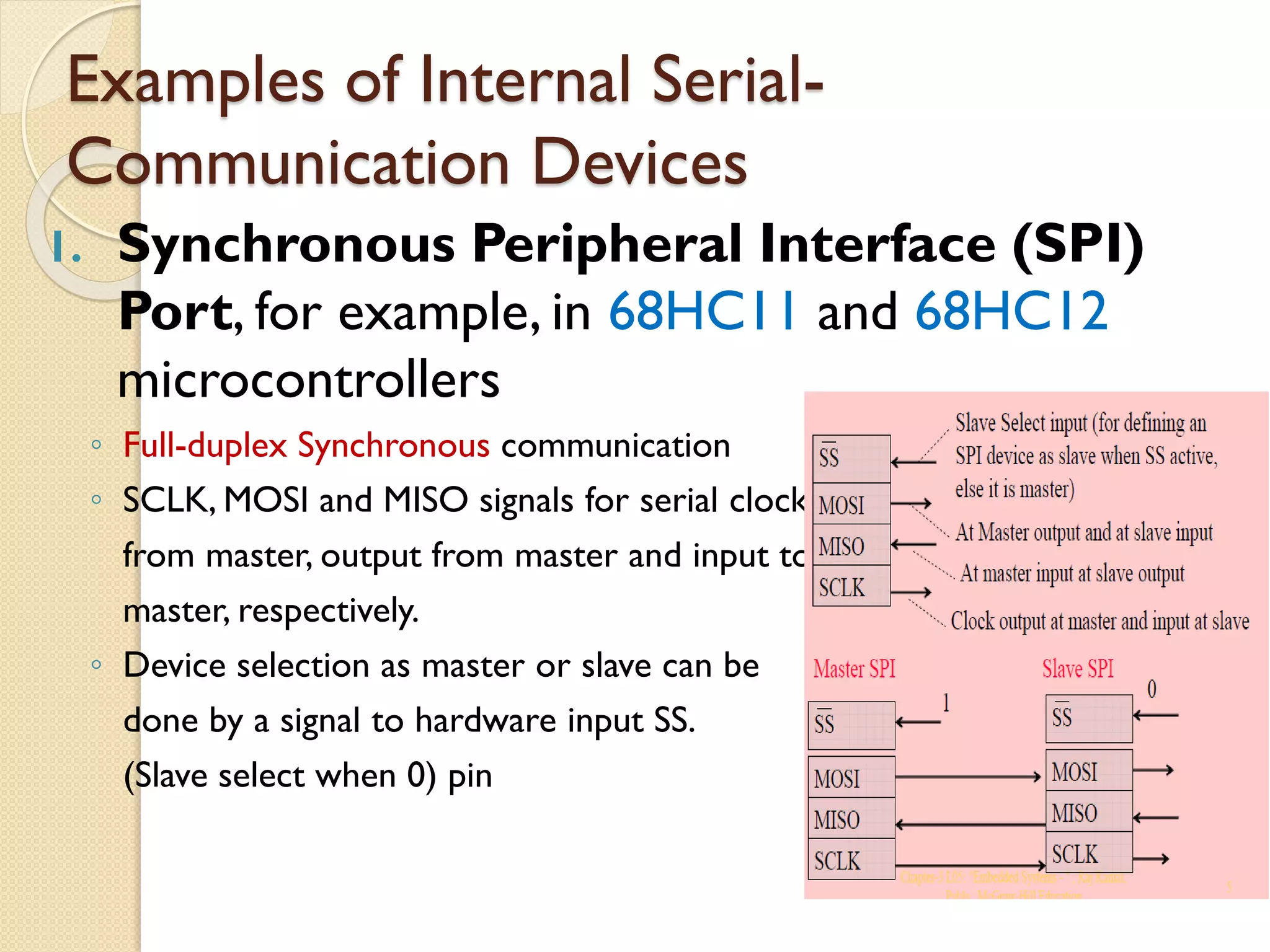
Examples of InternalSerial-
Communication Devices
1. Synchronous Peripheral Interface (SPI)
Port, for example, in 68HC11 and 68HC12
microcontrollers
◦ Full-duplex Synchronous communication
◦ SCLK, MOSI and MISO signals for serial clock
from master, output from master and input to
master, respectively.
◦ Device selection as master or slave can be
done by a signal to hardware input SS.
(Slave select when 0) pin
25.
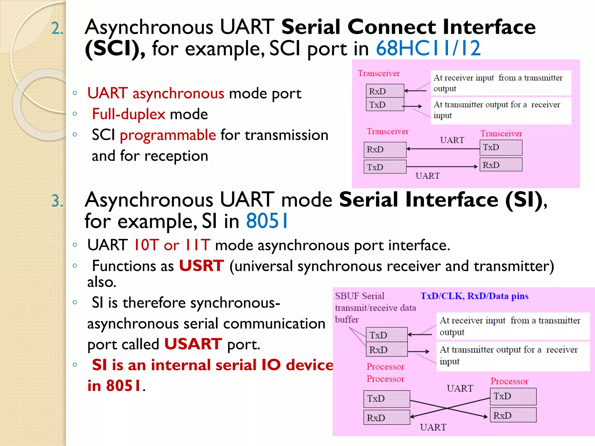
2. Asynchronous UARTSerial Connect Interface
(SCI), for example, SCI port in 68HC11/12
◦ UART asynchronous mode port
◦ Full-duplex mode
◦ SCI programmable for transmission
and for reception
3. Asynchronous UART mode Serial Interface (SI),
for example, SI in 8051
◦ UART 10T or 11T mode asynchronous port interface.
◦ Functions as USRT (universal synchronous receiver and transmitter)
also.
◦ SI is therefore synchronous-
asynchronous serial communication
port called USART port.
◦ SI is an internal serial IO device
in 8051.
26.
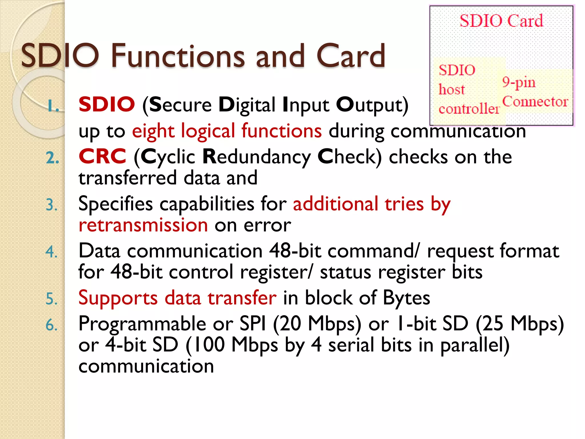
SDIO Functions andCard
1. SDIO (Secure Digital Input Output)
up to eight logical functions during communication
2. CRC (Cyclic Redundancy Check) checks on the
transferred data and
3. Specifies capabilities for additional tries by
retransmission on error
4. Data communication 48-bit command/ request format
for 48-bit control register/ status register bits
5. Supports data transfer in block of Bytes
6. Programmable or SPI (20 Mbps) or 1-bit SD (25 Mbps)
or 4-bit SD (100 Mbps by 4 serial bits in parallel)
communication
27.
PARALLEL DEVICE PORTS
8-bit IOs
Short distances, generally within a circuit board or IC
or nearby external devices
Advantage−
◦ Number of 8 bits over the wires in parallel.
◦ High data transfer rate
Disadvantage−
◦ More number of wires
◦ Capacitive effect in parallel wires reduces the length up to
which communication in parallel can take place.
◦ High capacitance results in delay for the bits at the other end
undergoing transition from 0 to 1 or 1 to 0.
◦ High capacitance can also result in noise and cross talk
(induced signals) between the wires.
28.
Parallel port interfacingsfor
keypad, LCD display and modem
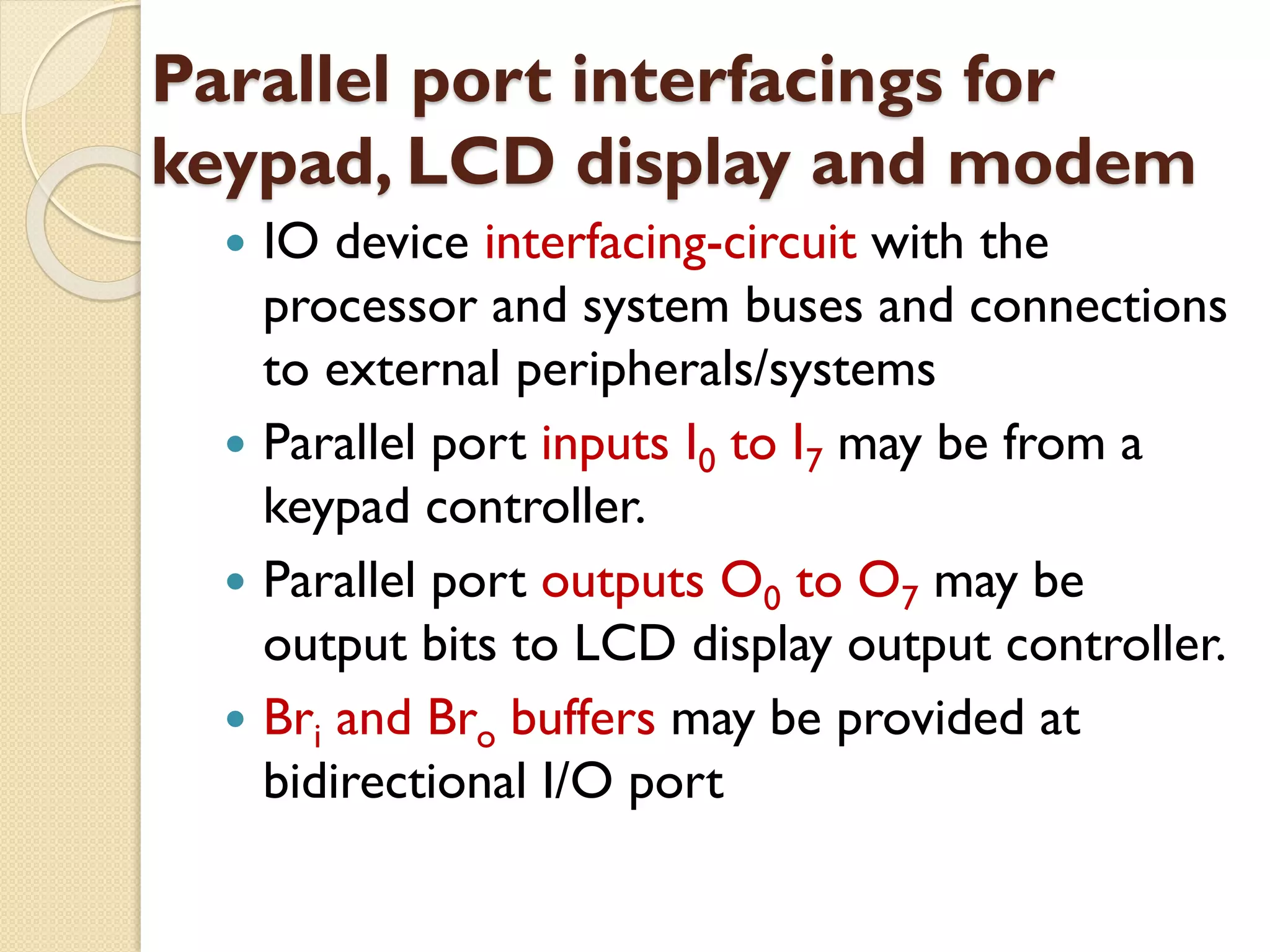
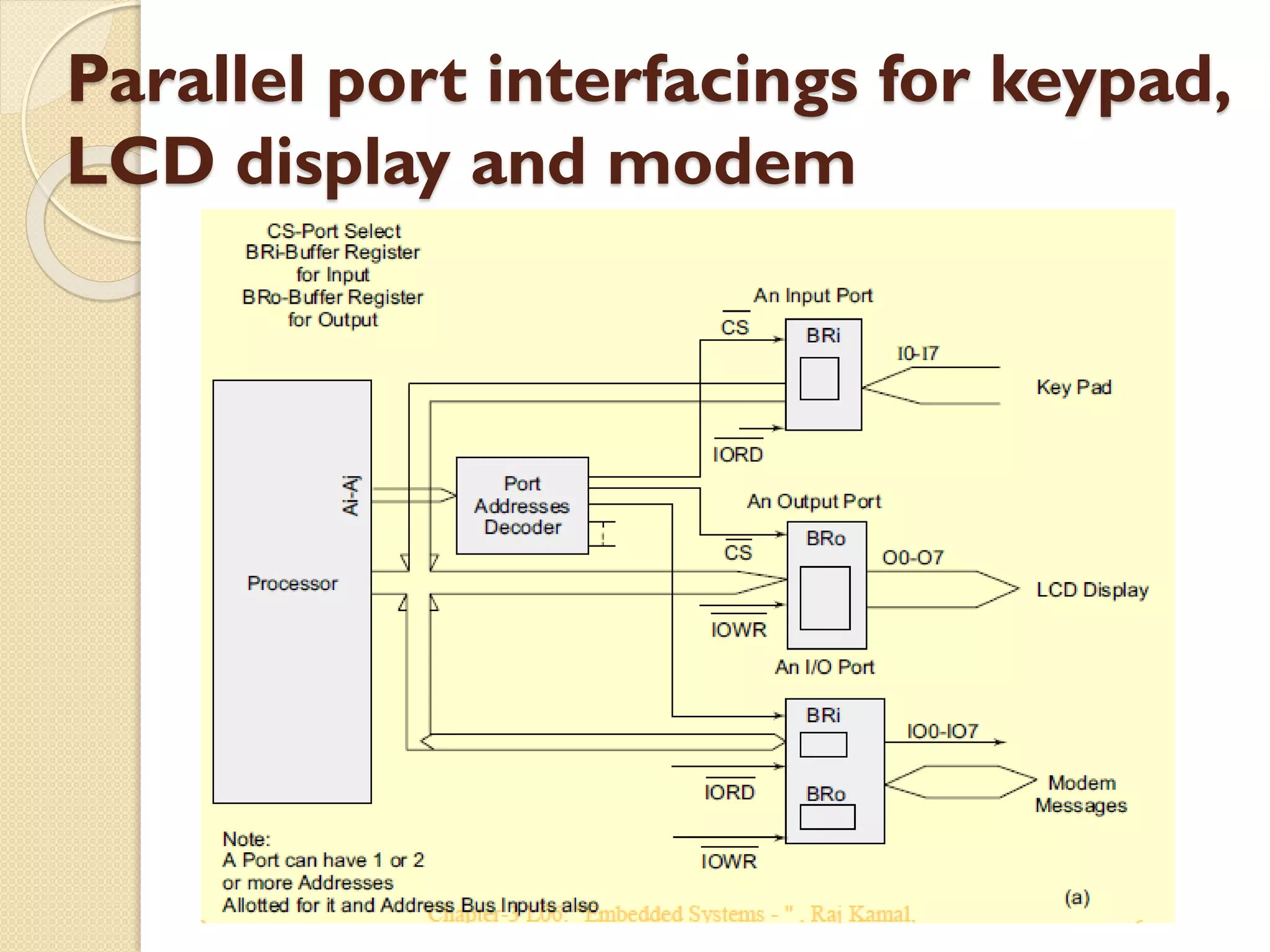
IO device interfacing-circuit with the
processor and system buses and connections
to external peripherals/systems
Parallel port inputs I0 to I7 may be from a
keypad controller.
Parallel port outputs O0 to O7 may be
output bits to LCD display output controller.
Bri and Bro buffers may be provided at
bidirectional I/O port
Handshaking signals toand from
an external peripheral device
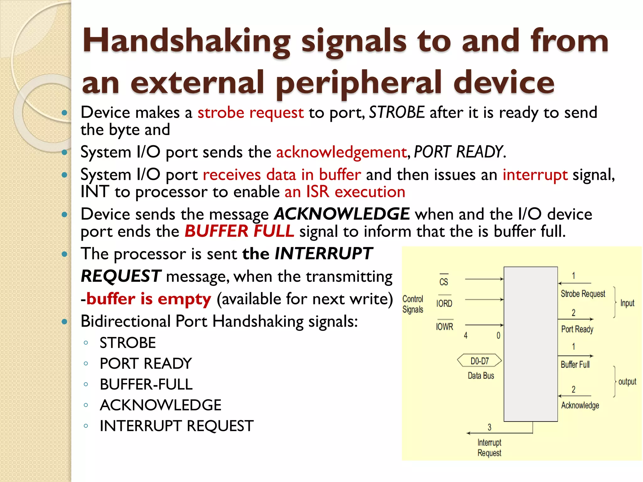
Device makes a strobe request to port, STROBE after it is ready to send
the byte and
System I/O port sends the acknowledgement, PORT READY.
System I/O port receives data in buffer and then issues an interrupt signal,
INT to processor to enable an ISR execution
Device sends the message ACKNOWLEDGE when and the I/O device
port ends the BUFFER FULL signal to inform that the is buffer full.
The processor is sent the INTERRUPT
REQUEST message, when the transmitting
-buffer is empty (available for next write)
Bidirectional Port Handshaking signals:
◦ STROBE
◦ PORT READY
◦ BUFFER-FULL
◦ ACKNOWLEDGE
◦ INTERRUPT REQUEST
31.
Special functionalities /
Characteristics:
1.A device or port may have multi-byte data input buffer(s)
and data output buffer(s).
2. A port may be with a DDR (Data Direction Register) (for
example, in 68HC11 microcontroller).
3. Port LSTTL driving capability and Port loading capability
are important characteristics.
4. Quasi bi-directional port − port limited driving capability
for a period of one or a few clock cycles and for one or a
few LSTTL gates only.
5. There may be multiple or alternate functionality in the
port pins.
6. A port may have provision for multiplexed output to
connect to multiple systems or units.
7. A port may have provision for demultiplexed inputs from
multiple systems or units.
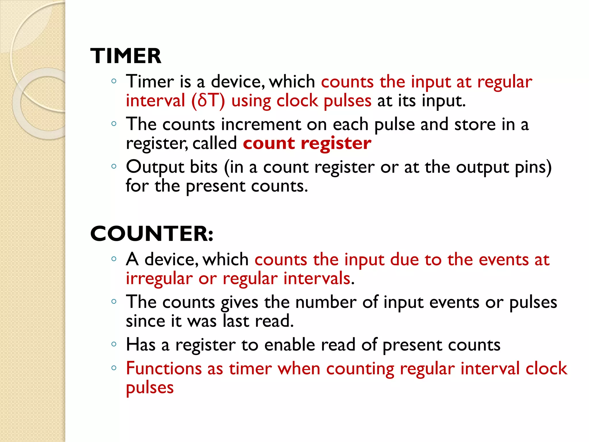
TIMER
◦ Timer isa device, which counts the input at regular
interval (δT) using clock pulses at its input.
◦ The counts increment on each pulse and store in a
register, called count register
◦ Output bits (in a count register or at the output pins)
for the present counts.
COUNTER:
◦ A device, which counts the input due to the events at
irregular or regular intervals.
◦ The counts gives the number of input events or pulses
since it was last read.
◦ Has a register to enable read of present counts
◦ Functions as timer when counting regular interval clock
pulses
34.
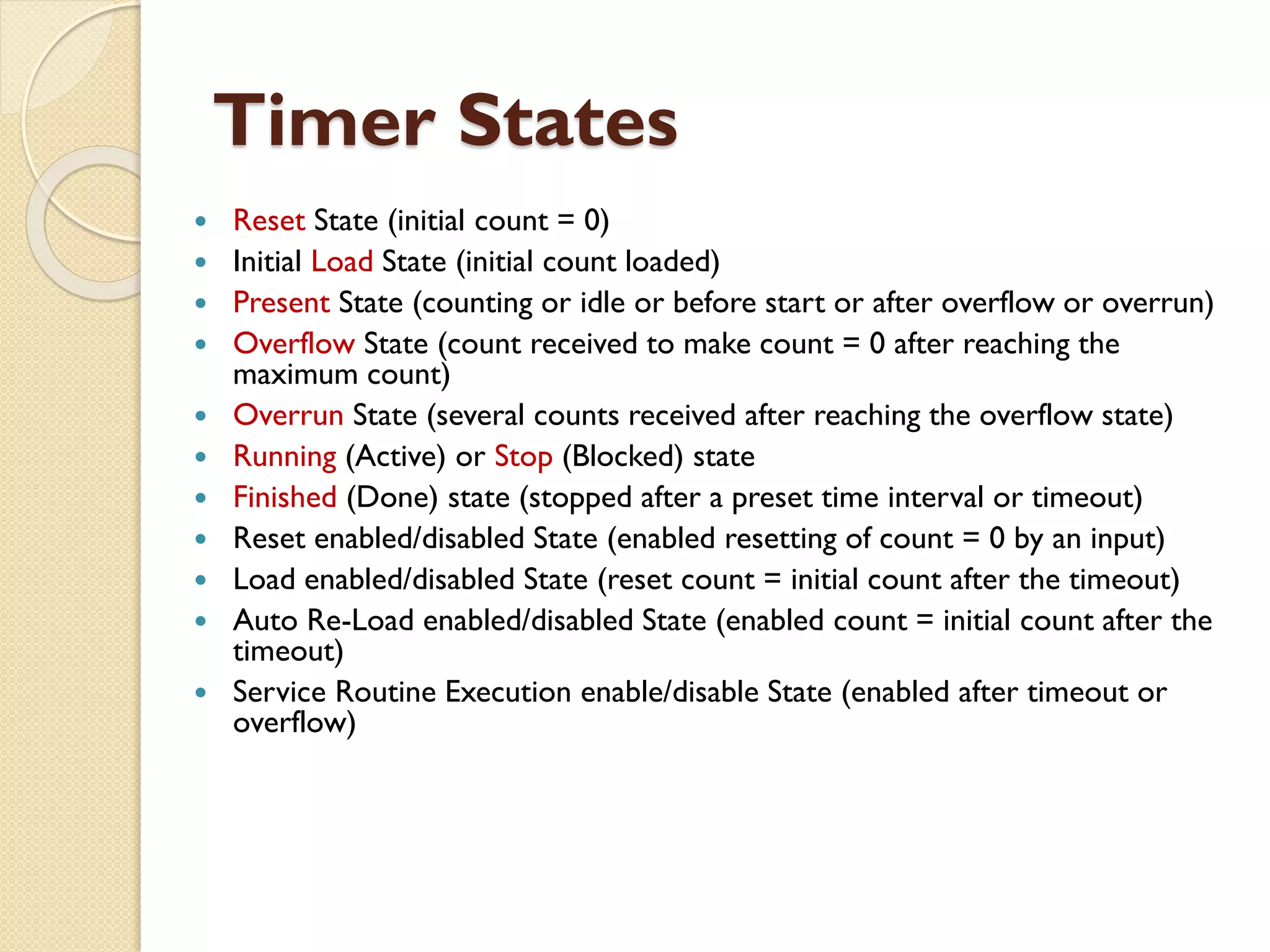
Timer States
ResetState (initial count = 0)
Initial Load State (initial count loaded)
Present State (counting or idle or before start or after overflow or overrun)
Overflow State (count received to make count = 0 after reaching the
maximum count)
Overrun State (several counts received after reaching the overflow state)
Running (Active) or Stop (Blocked) state
Finished (Done) state (stopped after a preset time interval or timeout)
Reset enabled/disabled State (enabled resetting of count = 0 by an input)
Load enabled/disabled State (reset count = initial count after the timeout)
Auto Re-Load enabled/disabled State (enabled count = initial count after the
timeout)
Service Routine Execution enable/disable State (enabled after timeout or
overflow)
35.
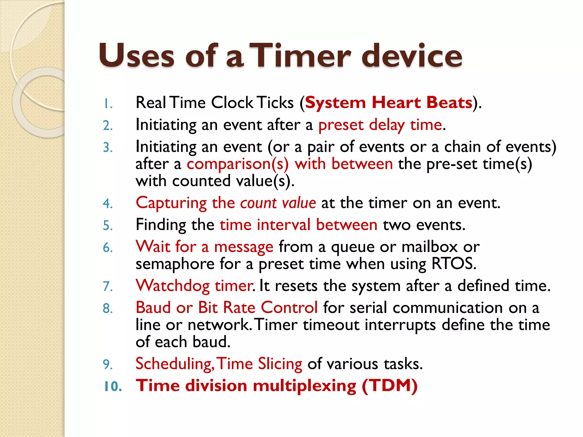
Uses of aTimerdevice
1. Real Time Clock Ticks (System Heart Beats).
2. Initiating an event after a preset delay time.
3. Initiating an event (or a pair of events or a chain of events)
after a comparison(s) with between the pre-set time(s)
with counted value(s).
4. Capturing the count value at the timer on an event.
5. Finding the time interval between two events.
6. Wait for a message from a queue or mailbox or
semaphore for a preset time when using RTOS.
7. Watchdog timer. It resets the system after a defined time.
8. Baud or Bit Rate Control for serial communication on a
line or network.Timer timeout interrupts define the time
of each baud.
9. Scheduling,Time Slicing of various tasks.
10. Time division multiplexing (TDM)
36.
Timer cum CountingDevice
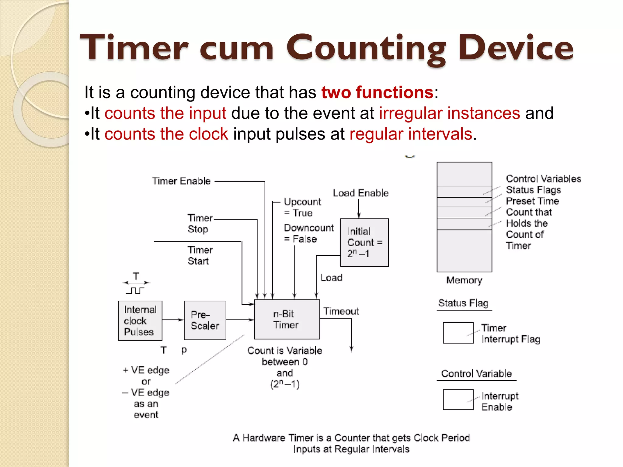
It is a counting device that has two functions:
•It counts the input due to the event at irregular instances and
•It counts the clock input pulses at regular intervals.
37.
Timer cum CountingDevice
Control bits are as per the hardware signals and
corresponding bits at the control register. Control bits
(or signals) can be of nine types.
1. Timer Enable (to activate a timer).
2. Timer Start (to start counting at each clock input).
3. Timer Stop (to stop counting) from next clock input).
4. Pre-scaling bits (to divide the clock-out frequency signal from the
processor).
5. Up count Enable (to enable up counting by incrementing the
count value on each clock input)
6. Down Count Enable (to decrement on a clock input).
7. Load Enable (to enable loading of a value at a register into the
timer).
8. Timer Interrupt Enable (to enable interrupt servicing when the
timer outs (overflows) and reaches count value = 0)
9. Timer Interrupt Enable [to enable interrupt servicing when the
timer overflows (reaches count =0)].
38.
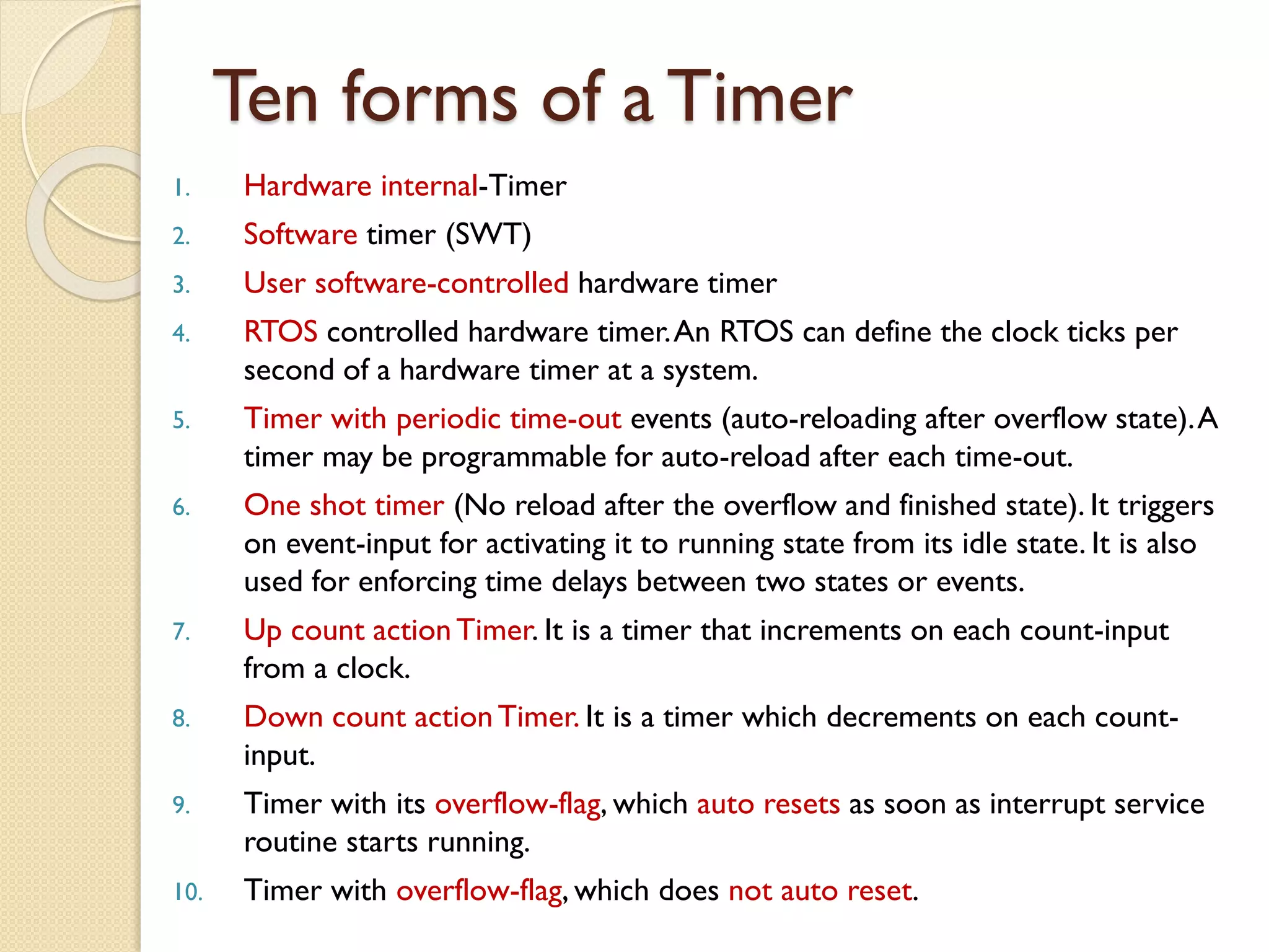
Ten forms ofa Timer
1. Hardware internal-Timer
2. Software timer (SWT)
3. User software-controlled hardware timer
4. RTOS controlled hardware timer.An RTOS can define the clock ticks per
second of a hardware timer at a system.
5. Timer with periodic time-out events (auto-reloading after overflow state).A
timer may be programmable for auto-reload after each time-out.
6. One shot timer (No reload after the overflow and finished state). It triggers
on event-input for activating it to running state from its idle state. It is also
used for enforcing time delays between two states or events.
7. Up count actionTimer. It is a timer that increments on each count-input
from a clock.
8. Down count actionTimer. It is a timer which decrements on each count-
input.
9. Timer with its overflow-flag, which auto resets as soon as interrupt service
routine starts running.
10. Timer with overflow-flag, which does not auto reset.
39.
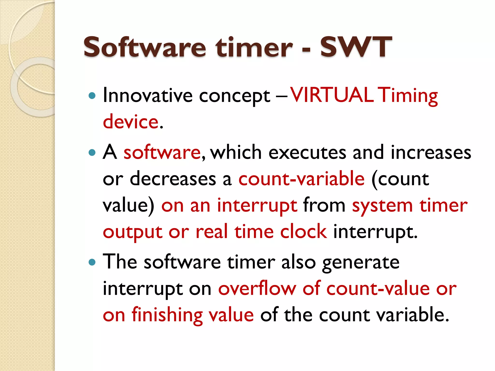
Software timer -SWT
Innovative concept –VIRTUAL Timing
device.
A software, which executes and increases
or decreases a count-variable (count
value) on an interrupt from system timer
output or real time clock interrupt.
The software timer also generate
interrupt on overflow of count-value or
on finishing value of the count variable.
40.
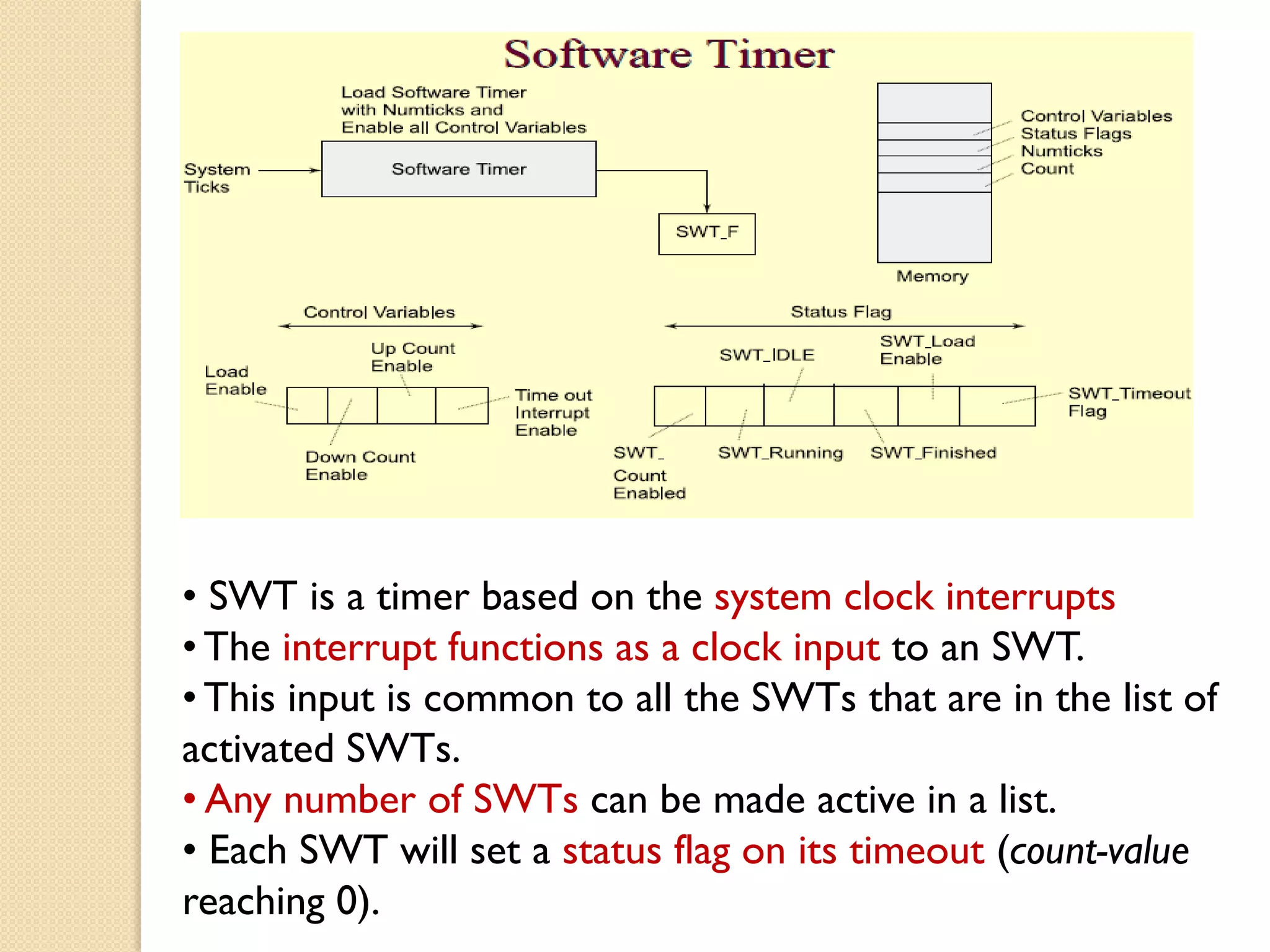
• SWT isa timer based on the system clock interrupts
• The interrupt functions as a clock input to an SWT.
• This input is common to all the SWTs that are in the list of
activated SWTs.
• Any number of SWTs can be made active in a list.
• Each SWT will set a status flag on its timeout (count-value
reaching 0).
41.
WATCHDOGTIMER:
A timingdevice such that it is set for a preset time interval and an event
must occur during that interval else the device will generate the timeout
signal on failure to get that event in the watched time interval.
On that event, the watchdog timer is disabled to disable generation of
timeout or reset
Timeout may result in processor start a service routine or start from
beginning
An application in mobile phone is that display is off in case no GUI
interaction takes place within a watched time interval.
REALTIME CLOCK:
A clock, which is based on the interrupts at preset intervals.An interrupt
service routine executes on each timeout (overflow) of this clock.This
timing device once started never resets or never reloaded with another
value.
Used in a system to save the time and date.
Used in a system to initiate return of control to the system (OS) after
the set system clock periods
42.
Serial Communication using‘I2C’,
‘CAN’ & Advanced Input Output
buses between the Networked
Multiple Devices
43.
Embedded systems networking
Embedded systems can be distributed and networked
using an IO bus or networking protocol
◦ Serial bus protocols
I2C bus
CAN bus
USB bus
◦ Parallel bus protocols
ISA
PCI
PCI-X
◦ Internet protocols
HTTP,TCP, IP etc.,
◦ Wireless protocols
Bluetooth, ZigBee etc.,
44.
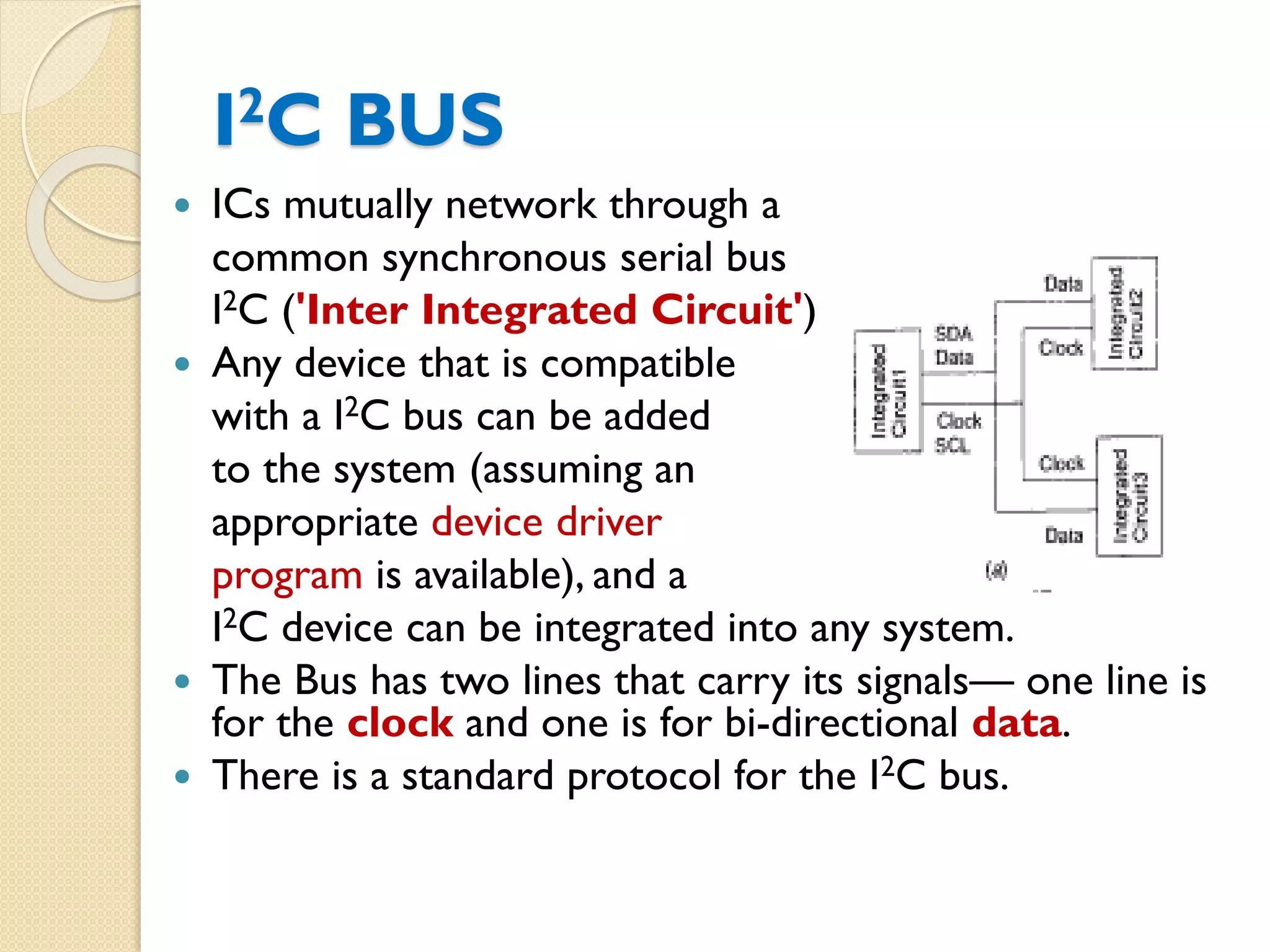
I2C BUS
ICsmutually network through a
common synchronous serial bus
I2C ('Inter Integrated Circuit')
Any device that is compatible
with a I2C bus can be added
to the system (assuming an
appropriate device driver
program is available), and a
I2C device can be integrated into any system.
The Bus has two lines that carry its signals— one line is
for the clock and one is for bi-directional data.
There is a standard protocol for the I2C bus.
45.
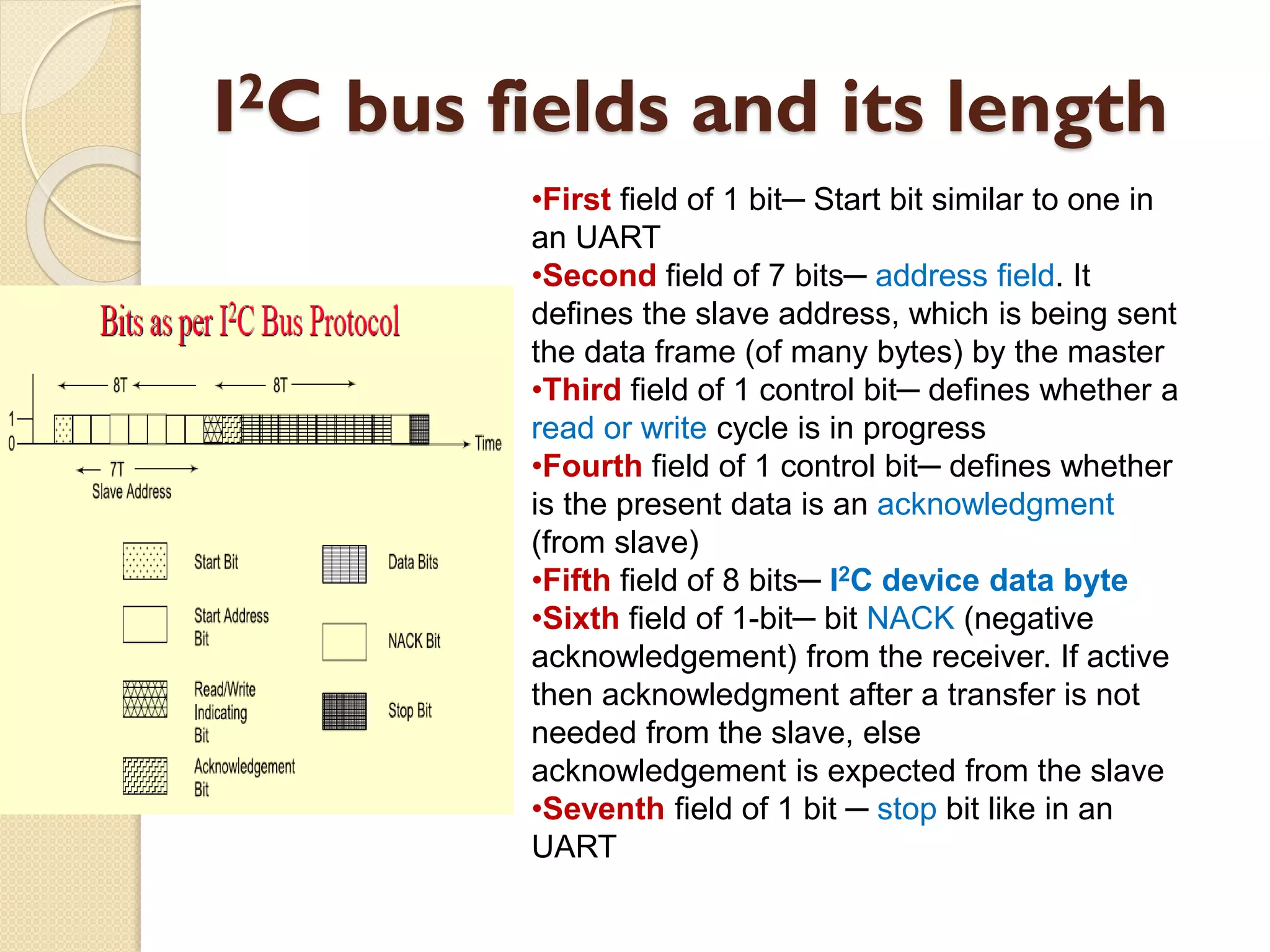
I2C bus fieldsand its length
•First field of 1 bit─ Start bit similar to one in
an UART
•Second field of 7 bits─ address field. It
defines the slave address, which is being sent
the data frame (of many bytes) by the master
•Third field of 1 control bit─ defines whether a
read or write cycle is in progress
•Fourth field of 1 control bit─ defines whether
is the present data is an acknowledgment
(from slave)
•Fifth field of 8 bits─ I2C device data byte
•Sixth field of 1-bit─ bit NACK (negative
acknowledgement) from the receiver. If active
then acknowledgment after a transfer is not
needed from the slave, else
acknowledgement is expected from the slave
•Seventh field of 1 bit ─ stop bit like in an
UART
46.
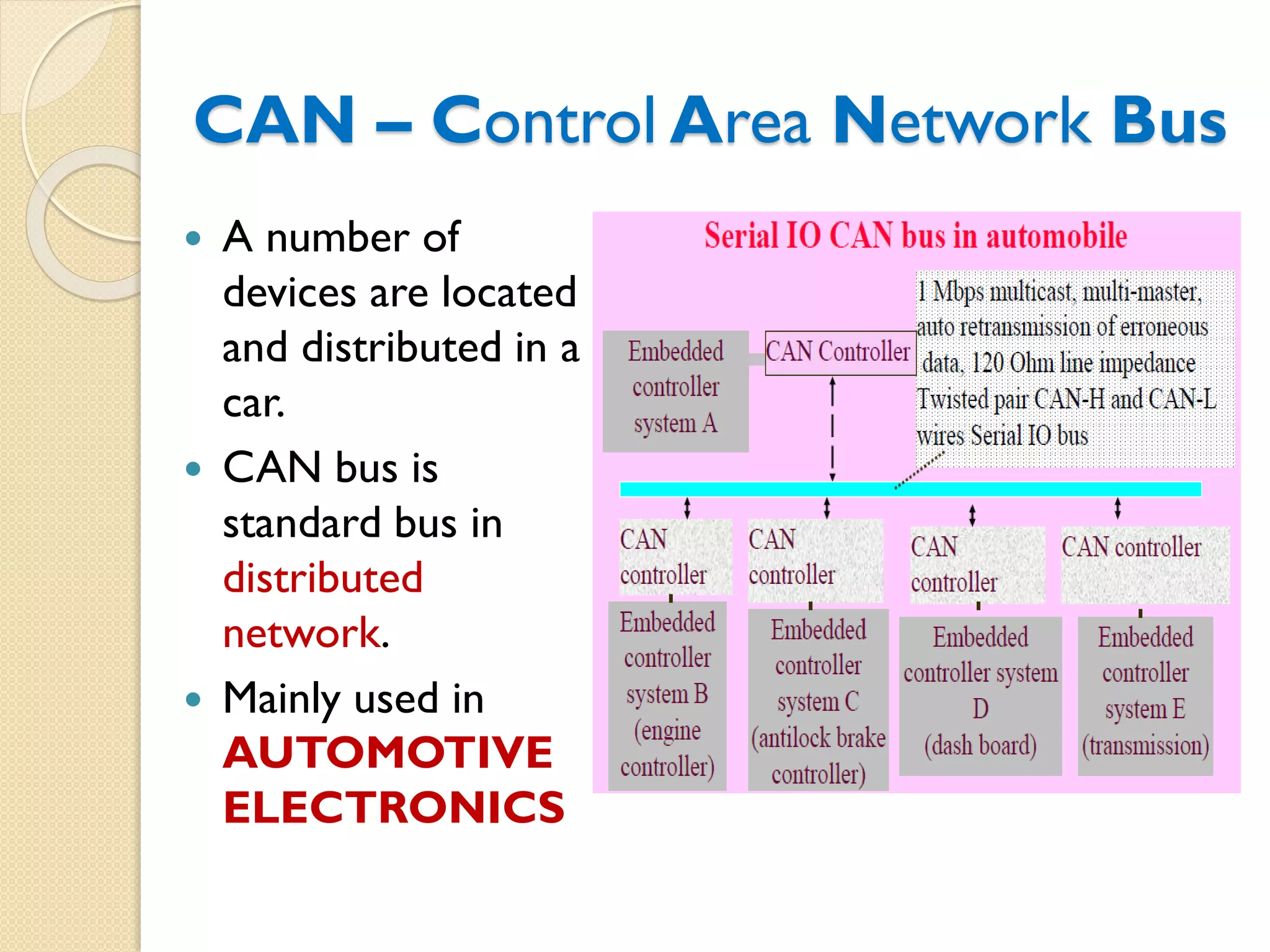
CAN – ControlArea Network Bus
A number of
devices are located
and distributed in a
car.
CAN bus is
standard bus in
distributed
network.
Mainly used in
AUTOMOTIVE
ELECTRONICS
47.
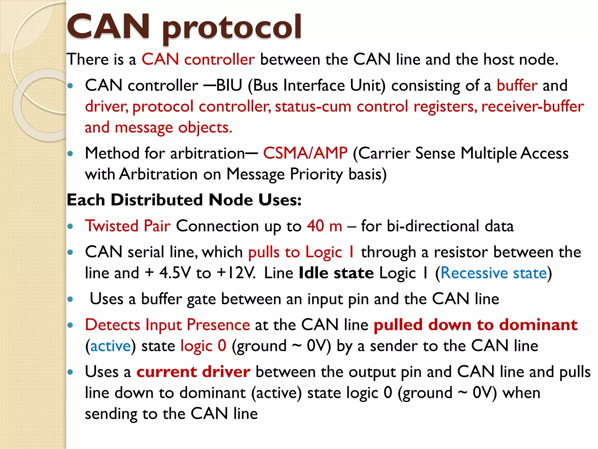
CAN protocol
There isa CAN controller between the CAN line and the host node.
CAN controller ─BIU (Bus Interface Unit) consisting of a buffer and
driver, protocol controller, status-cum control registers, receiver-buffer
and message objects.
Method for arbitration─ CSMA/AMP (Carrier Sense Multiple Access
with Arbitration on Message Priority basis)
Each Distributed Node Uses:
Twisted Pair Connection up to 40 m – for bi-directional data
CAN serial line, which pulls to Logic 1 through a resistor between the
line and + 4.5V to +12V. Line Idle state Logic 1 (Recessive state)
Uses a buffer gate between an input pin and the CAN line
Detects Input Presence at the CAN line pulled down to dominant
(active) state logic 0 (ground ~ 0V) by a sender to the CAN line
Uses a current driver between the output pin and CAN line and pulls
line down to dominant (active) state logic 0 (ground ~ 0V) when
sending to the CAN line
48.
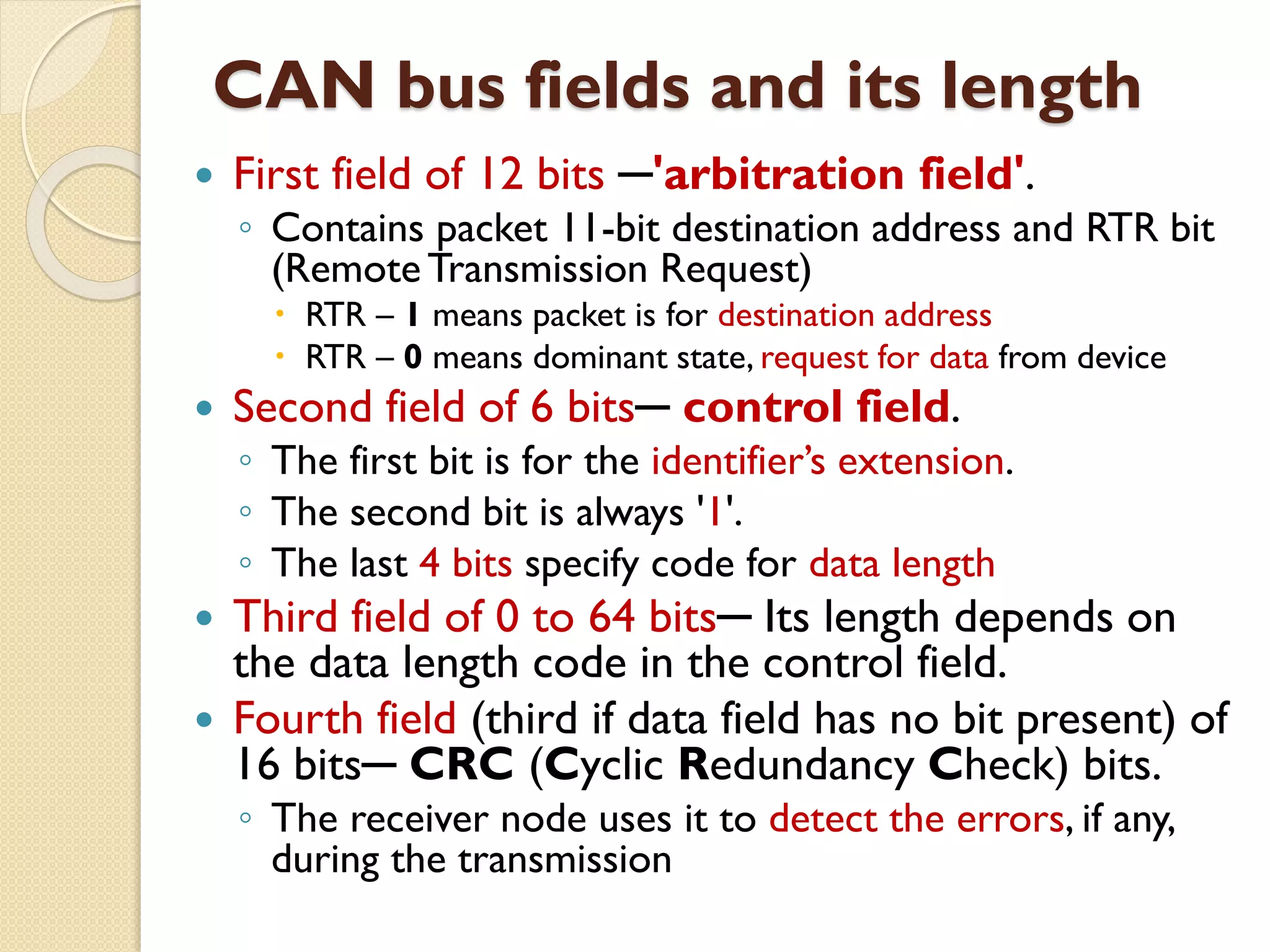
CAN bus fieldsand its length
First field of 12 bits ─'arbitration field'.
◦ Contains packet 11-bit destination address and RTR bit
(RemoteTransmission Request)
RTR – 1 means packet is for destination address
RTR – 0 means dominant state, request for data from device
Second field of 6 bits─ control field.
◦ The first bit is for the identifier’s extension.
◦ The second bit is always '1'.
◦ The last 4 bits specify code for data length
Third field of 0 to 64 bits─ Its length depends on
the data length code in the control field.
Fourth field (third if data field has no bit present) of
16 bits─ CRC (Cyclic Redundancy Check) bits.
◦ The receiver node uses it to detect the errors, if any,
during the transmission
49.
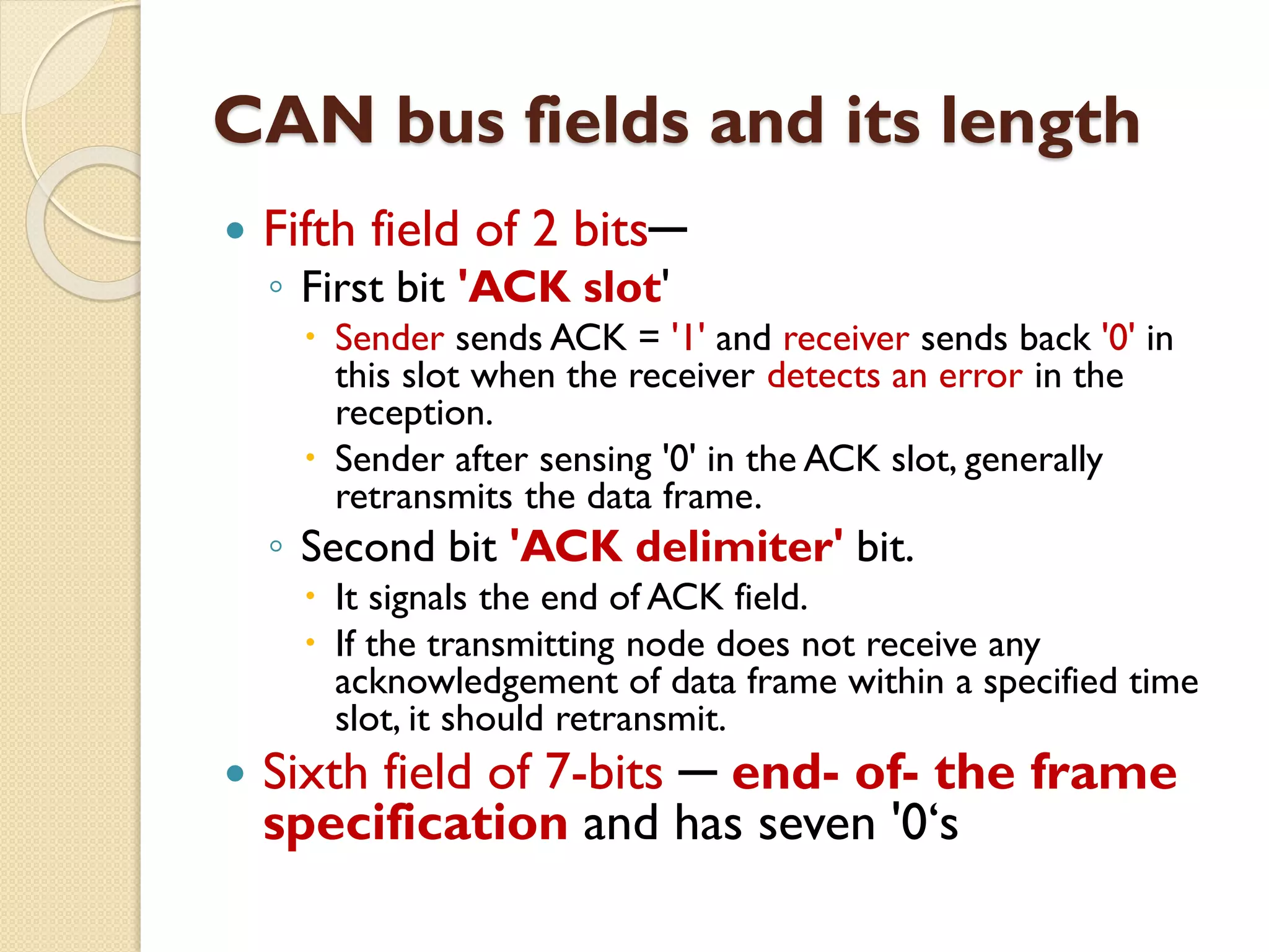
CAN bus fieldsand its length
Fifth field of 2 bits─
◦ First bit 'ACK slot'
Sender sends ACK = '1' and receiver sends back '0' in
this slot when the receiver detects an error in the
reception.
Sender after sensing '0' in the ACK slot, generally
retransmits the data frame.
◦ Second bit 'ACK delimiter' bit.
It signals the end of ACK field.
If the transmitting node does not receive any
acknowledgement of data frame within a specified time
slot, it should retransmit.
Sixth field of 7-bits ─ end- of- the frame
specification and has seven '0‘s
50.
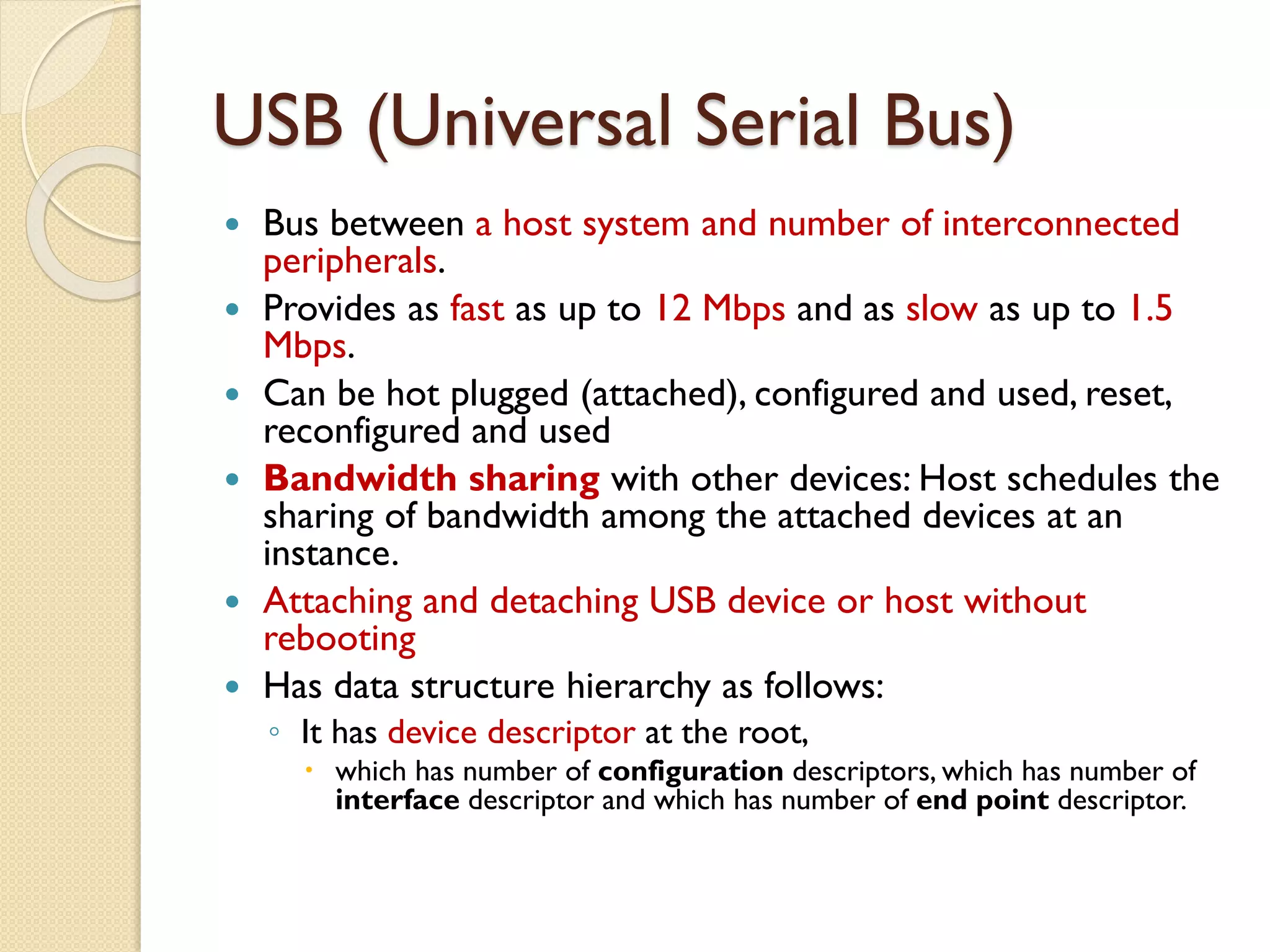
USB (Universal SerialBus)
Bus between a host system and number of interconnected
peripherals.
Provides as fast as up to 12 Mbps and as slow as up to 1.5
Mbps.
Can be hot plugged (attached), configured and used, reset,
reconfigured and used
Bandwidth sharing with other devices: Host schedules the
sharing of bandwidth among the attached devices at an
instance.
Attaching and detaching USB device or host without
rebooting
Has data structure hierarchy as follows:
◦ It has device descriptor at the root,
which has number of configuration descriptors, which has number of
interface descriptor and which has number of end point descriptor.
51.
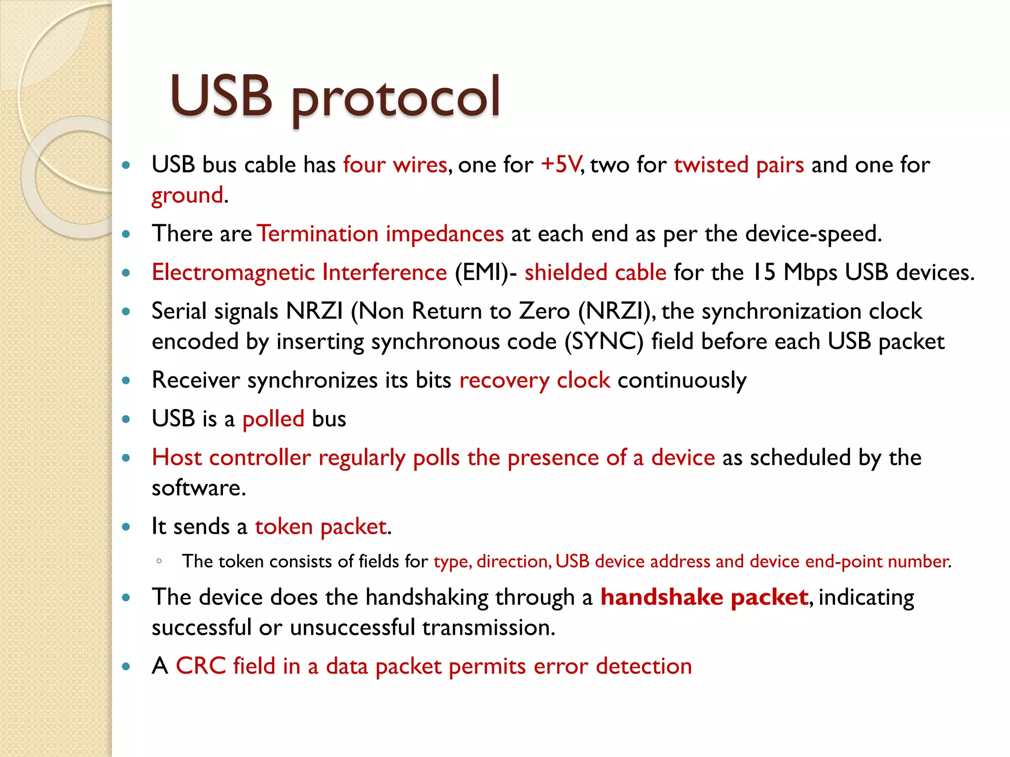
USB protocol
USBbus cable has four wires, one for +5V, two for twisted pairs and one for
ground.
There are Termination impedances at each end as per the device-speed.
Electromagnetic Interference (EMI)- shielded cable for the 15 Mbps USB devices.
Serial signals NRZI (Non Return to Zero (NRZI), the synchronization clock
encoded by inserting synchronous code (SYNC) field before each USB packet
Receiver synchronizes its bits recovery clock continuously
USB is a polled bus
Host controller regularly polls the presence of a device as scheduled by the
software.
It sends a token packet.
◦ The token consists of fields for type, direction, USB device address and device end-point number.
The device does the handshaking through a handshake packet, indicating
successful or unsuccessful transmission.
A CRC field in a data packet permits error detection
52.
USB Bus
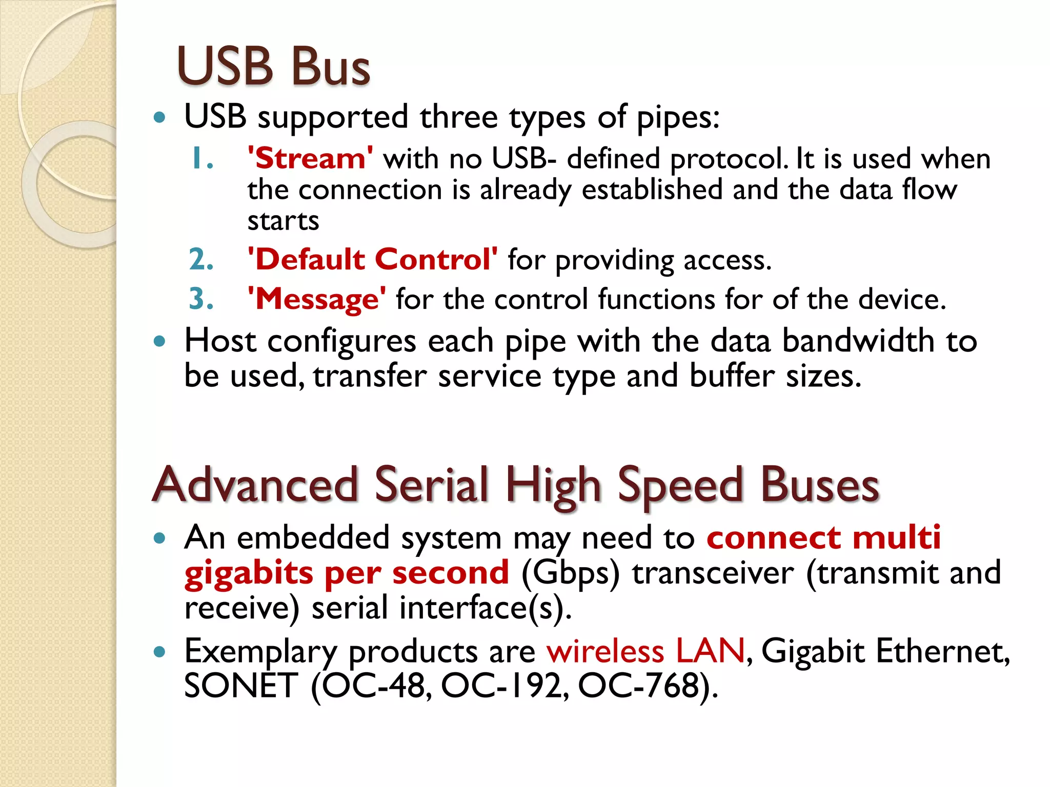
USBsupported three types of pipes:
1. 'Stream' with no USB- defined protocol. It is used when
the connection is already established and the data flow
starts
2. 'Default Control' for providing access.
3. 'Message' for the control functions for of the device.
Host configures each pipe with the data bandwidth to
be used, transfer service type and buffer sizes.
Advanced Serial High Speed Buses
An embedded system may need to connect multi
gigabits per second (Gbps) transceiver (transmit and
receive) serial interface(s).
Exemplary products are wireless LAN, Gigabit Ethernet,
SONET (OC-48, OC-192, OC-768).
53.
Host system orComputer
Parallel Communication
between the Networked Input
Output multiple devices using
ISA, PCI, PCI-X and Advanced
Buses
54.
ISA (IBM StandardArchitecture) Bus
Connects only to an embedded device that has an 8086 or
80186 or 80256 processor, and
In which the processor addressing and IBM PC architecture
addressing limitations and interrupt vector address
assignments are taken into account.
There is no geographical addressing.
Limitation: ISA bus memory accesses can be in two ranges,
640 kB to 1 MB and 15 to 16 MB
IO port address limitations for devices: 8086 to 80286
processor has IO mapped IOs, not memory mapped IOs.
ISA and EISA buses are compatible with IBM
architecture.They are used for connecting devices following
IO addresses and interrupt vectors as per IBM PC
architecture. EISA is 32-bit extension of ISA. It also
supports software interrupt functions and Ethernet devices.
55.
Peripheral Component Interconnect
(PCI)Bus:
Platform-Independent from the IBM
architecture.
Number of embedded devices in a computer
system use PCI
Standards:
◦ PCI 32bit/33 MHz, and 64bit/66 MHz
◦ PCI Extended (PCI/X) 64 bit/100 MHz ,
Two super speed versions:
◦ PCI SuperV2.3 264/528 MBps 3.3V (on 64- bit
bus), and 132/264 (on 32-bit bus) and
◦ PCI-X SuperV1.01a for 800MBps 64- bit bus
3.3Volt.
56.
PCI Bus Feature:
32- bit data/address bus extendible to 64 bits.
PCI protocol specifies the ways of interaction
between the different components of a computer.A
specification version 2.1
Synchronous/asynchronous throughput is up to 132/
528 MB/s [33M × 4/ 66M × 8 Byte/s],
Operates on 3.3V to 5V signals.
PCI driver can access the hardware automatically as
well as by the programmer assigned addresses.
Automatically detects the interfacing systems and
assigns new addresses
Thus, simplified addition and deletion (attachment and
detachment) of the system peripherals.
57.
PCI device identification
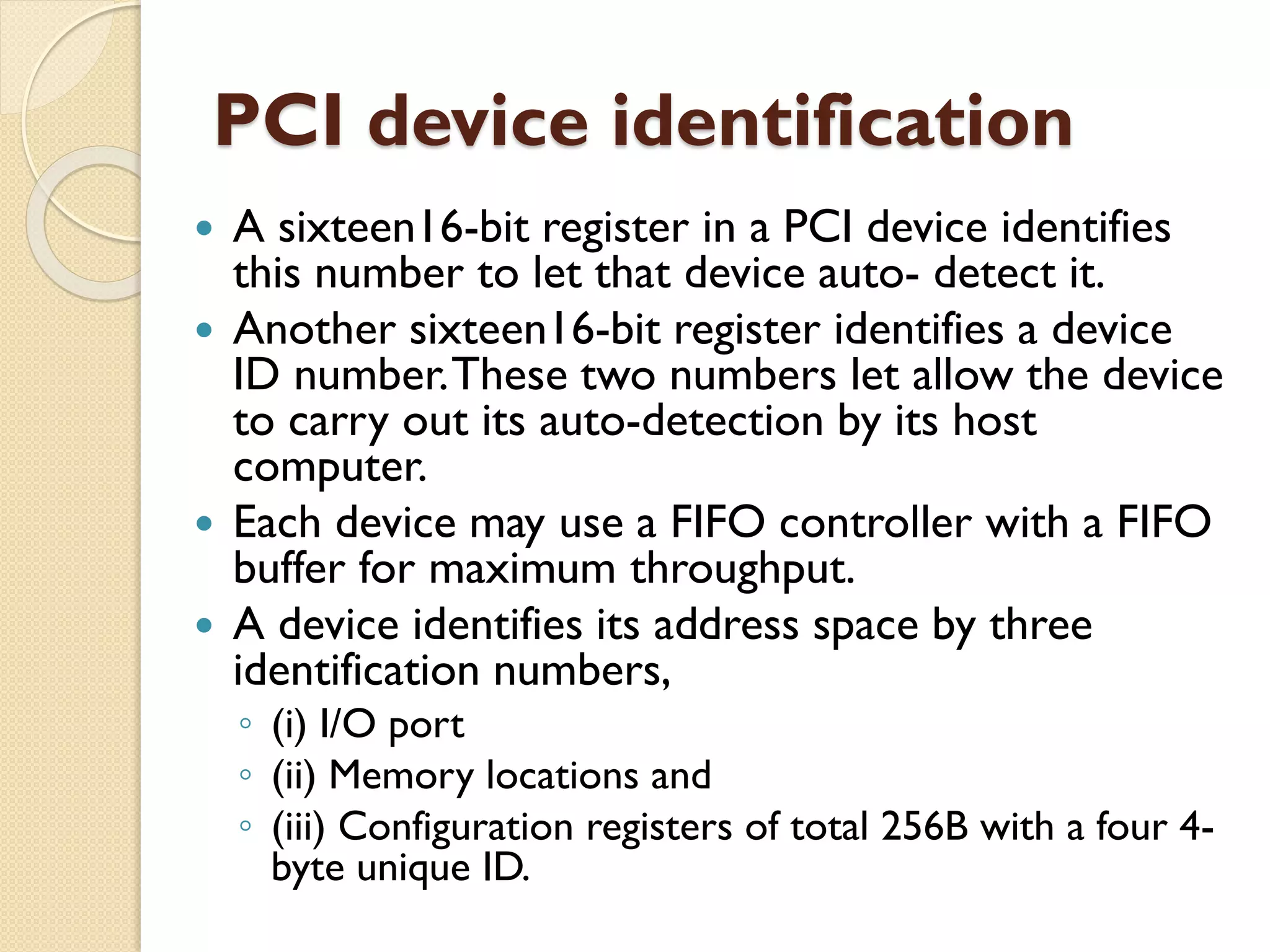
A sixteen16-bit register in a PCI device identifies
this number to let that device auto- detect it.
Another sixteen16-bit register identifies a device
ID number.These two numbers let allow the device
to carry out its auto-detection by its host
computer.
Each device may use a FIFO controller with a FIFO
buffer for maximum throughput.
A device identifies its address space by three
identification numbers,
◦ (i) I/O port
◦ (ii) Memory locations and
◦ (iii) Configuration registers of total 256B with a four 4-
byte unique ID.
58.
PCI Configuration register- 60
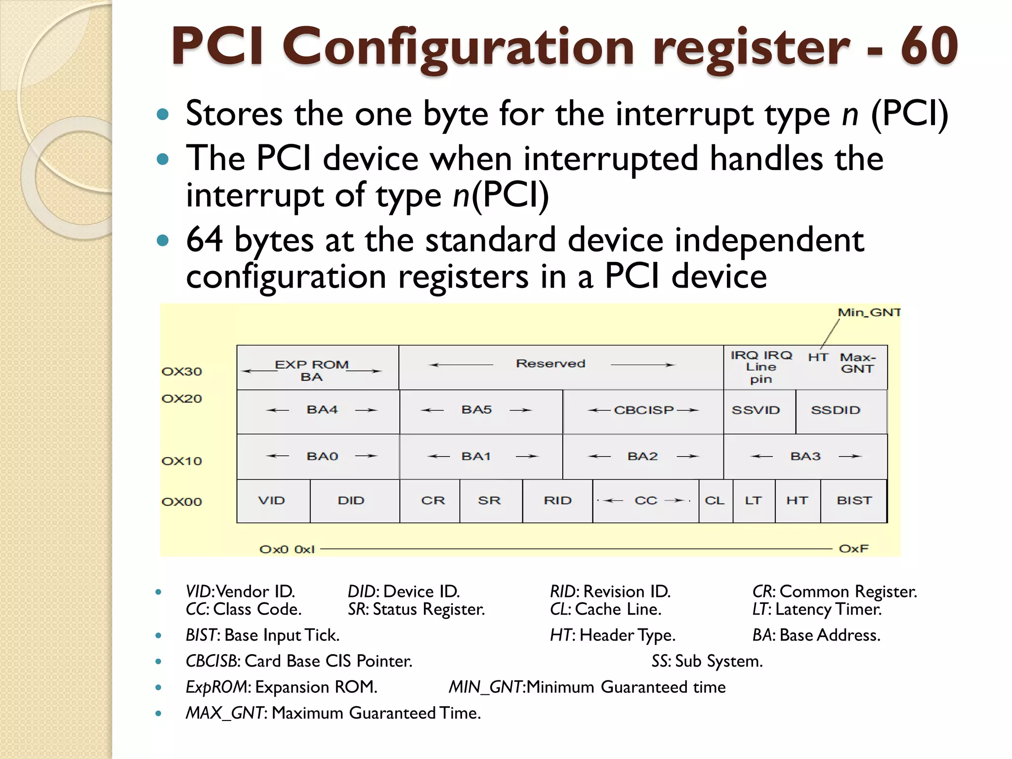
Stores the one byte for the interrupt type n (PCI)
The PCI device when interrupted handles the
interrupt of type n(PCI)
64 bytes at the standard device independent
configuration registers in a PCI device
VID:Vendor ID. DID: Device ID. RID: Revision ID. CR: Common Register.
CC: Class Code. SR: Status Register. CL: Cache Line. LT: Latency Timer.
BIST: Base Input Tick. HT: Header Type. BA: Base Address.
CBCISB: Card Base CIS Pointer. SS: Sub System.
ExpROM: Expansion ROM. MIN_GNT:Minimum Guaranteed time
MAX_GNT: Maximum Guaranteed Time.
59.
PCI Device Initialization:
•Adevice can initialize at booting time
•Avoids any address collision
•Device on boot up disables its interrupt and closes its door to its
address space except to the configuration registers space
PCI BIOS (Basic Input-Output System):
Performs the configuration transactions and then, memory and
address spaces automatically map to the address space in the
device hosting system
PCI-X (PCI extended) option:
•Maximum 264 MBps throughput, uses 8, 16, 32, or 64 bit
transfers
•6U cards contain additional pins for user defined I/Os
•Live insertion support (Hot-Swap),
•Supports two independent buses on the back plane (on different
connectors)
•Supports Ethernet, Infiniband, and Star Fabric support (Switched
fabric based systems) Compact PCI (cPCI)
60.
Advanced Parallel HighSpeed Buses
Following are advanced bus standard and
proprietary protocols developed recently
1. GMII (Gigabit Ethernet MAC Interchange
Interface).
2. XGMI (10 Gigabit Ethernet MAC Interchange
Interface)
3. CSIX-1. 66 Gbps 32-bit HSTL with 200 MHz
performance.
4. RapidIOTM Interconnect Specification v1.1 at 8
Gbps with 500 MBps performance or 250 MHz
dual direction registering performance using 8-
bit LVDS (LowVoltage Data Bus).
![EMBEDDED SYSTEM DESIGN
[10EI82]
Unit 3 -
DEVICES & BUSES FOR
DEVICE NETWORKS
By,
Mrs. Pavithra S
Asst. Prof, GSSSIETW](https://image.slidesharecdn.com/unit-3devicesbuses-180404082940/75/Unit-3-devices-amp-buses-1-2048.jpg)
![Examples ofVarious types of I/O devices
Synchronous
Serial Input
Inter-processor data transfer, reading from CD or hard disk, audio
input, video input, dial tone, network input, transceiver input, scanner
input, remote controller input, serial I/O bus input, writing to flash
memory using SDIO (Secure Data Association IO based card)
Synchronous
Serial Output
Inter-processor data transfer, multiprocessor communication, writing to
CD or hard disk, audio Input/output, video Input/output, dialler output,
network device output, remoteTV Control, transceiver output, and serial
I/O bus output or writing to flash memory using SDIO
Serial
Asynchronous
UART Input
Keypad controller serial data-in, mice, keyboard controller, modem
input, character send inputs on serial line [also called UART (universal
receiverand transmitter) input when according to UART mode]
Serial
Asynchronous
UART Output
Output from modem, output for printer, the output on a serial line
[also called UART output when according to UART]
I/O DeviceType Examples](https://image.slidesharecdn.com/unit-3devicesbuses-180404082940/75/Unit-3-devices-amp-buses-5-2048.jpg)
![Synchronous Serial Input:
•The sender along with the serial bits also sends the clock pulses SCLK (serial clock) to
the receiver port pin.The port synchronizes the serial data input bits with clock bits.
•The bytes are received at constant rates. Each byte at input port separates by 8T and data
transfer rate for the serial line bits is (1/T) bps. [1bps = 1 bit per s]
Synchronous Serial Output:
• Each bit in each byte sent in synchronization with a clock.
• Bytes sent at constant rates. If clock period =T, then data transfer rate is (1/T) bps.
Synchronous Serial Input / Output :
• Each bit in each byte is in synchronization at input and each bit in each byte is in
synchronization at output with the master clock output .
•The bytes are sent or received at constant rates.
Asynchronous Serial input:
• Does not receive the clock pulses or clock information along with the bits.
• Each bit is received in each byte at fixed intervals but each received byte is not in
synchronization.
• Bytes separate by the variable intervals or phase differences
• Asynchronous serial input also called UART input if serial input is according to UART
protocol](https://image.slidesharecdn.com/unit-3devicesbuses-180404082940/75/Unit-3-devices-amp-buses-8-2048.jpg)
![Communication Protocols
A protocol is a standard adopted, which
tells the way in which the bits of a frame
must be sent from a device (or controller
or port or processor) to another device
or system.
[Even in personal communication we
follow a protocol – we say Hello!Then
talk and then say good bye!]](https://image.slidesharecdn.com/unit-3devicesbuses-180404082940/75/Unit-3-devices-amp-buses-18-2048.jpg)
![Timer cum Counting Device
Control bits are as per the hardware signals and
corresponding bits at the control register. Control bits
(or signals) can be of nine types.
1. Timer Enable (to activate a timer).
2. Timer Start (to start counting at each clock input).
3. Timer Stop (to stop counting) from next clock input).
4. Pre-scaling bits (to divide the clock-out frequency signal from the
processor).
5. Up count Enable (to enable up counting by incrementing the
count value on each clock input)
6. Down Count Enable (to decrement on a clock input).
7. Load Enable (to enable loading of a value at a register into the
timer).
8. Timer Interrupt Enable (to enable interrupt servicing when the
timer outs (overflows) and reaches count value = 0)
9. Timer Interrupt Enable [to enable interrupt servicing when the
timer overflows (reaches count =0)].](https://image.slidesharecdn.com/unit-3devicesbuses-180404082940/75/Unit-3-devices-amp-buses-37-2048.jpg)
![PCI Bus Feature:
32- bit data/address bus extendible to 64 bits.
PCI protocol specifies the ways of interaction
between the different components of a computer.A
specification version 2.1
Synchronous/asynchronous throughput is up to 132/
528 MB/s [33M × 4/ 66M × 8 Byte/s],
Operates on 3.3V to 5V signals.
PCI driver can access the hardware automatically as
well as by the programmer assigned addresses.
Automatically detects the interfacing systems and
assigns new addresses
Thus, simplified addition and deletion (attachment and
detachment) of the system peripherals.](https://image.slidesharecdn.com/unit-3devicesbuses-180404082940/75/Unit-3-devices-amp-buses-56-2048.jpg)