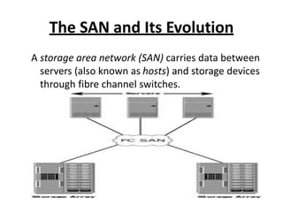
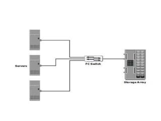
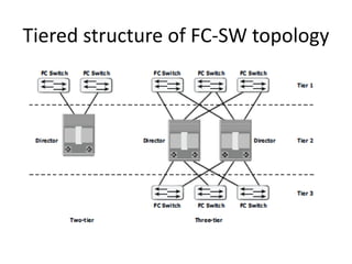
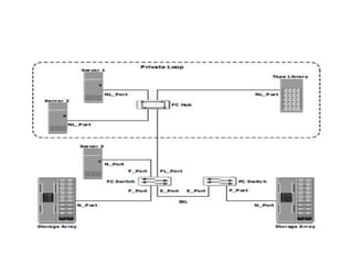
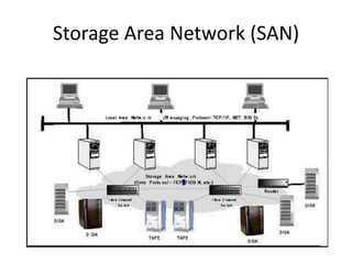
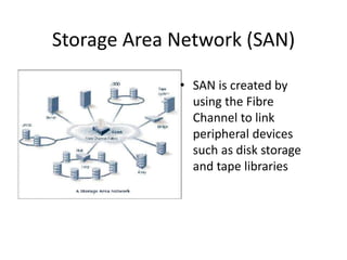
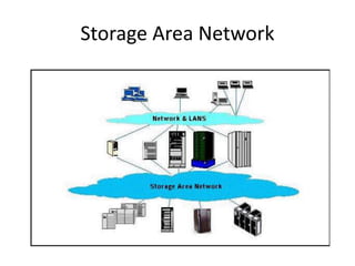
Unit -II
Storage Area Network (SAN)
The SAN and Its Evolution
A storage area network (SAN) carries data between
servers (also known as hosts) and storage devices
through fibre channel switches.
• In its earliest implementation, the SAN was a
simple grouping of hosts and the associated
storage that was connected to a network
using a hub as a connectivity device. This
configuration of a SAN is known as a Fibre
Channel Arbitrated Loop
• Two popular protocols that extend block-level
access to applications over IP are iSCSI and
Fibre Channel over IP (FCIP).
FC SAN Evolution
Components of SAN
• A SAN consists of three basic components:
servers, network infrastructure, and storage.
These components can be further broken
down into the following key elements: node
ports, cabling, interconnecting devices (such
as FC switches or hubs), storage arrays, and
SAN management software.
Node Ports
• In fibre channel, devices such as hosts, storage and tape
libraries are all referred to as nodes. Each node is a source or
destination of information for one or more nodes.
• A port operates in full-duplex data transmission mode with a
transmit (Tx) link and a receive (Rx) link
Cabling
SAN implementations use optical fiber cabling. Copper can
be used for shorter distances for back-end connectivity, as
it provides a better signal-to-noise ratio for distances up to
30 meters.
– Optical fiber cables carry data in the form of light.
• There are two types of optical cables, multi-mode and single-
mode
– A Standard connector (SC) and a Lucent connector (LC) are
two commonly used connectors for fiber optic cables.
– A Straight Tip (ST) is a fiber optic connector with a plug
and a socket that is locked with a half-twisted bayonet
lock.
Interconnect Devices
– Hubs, switches, and directors are the interconnect
devices commonly used in SAN.
– Hubs are used as communication devices in FC-AL
implementations.
– Switches are more intelligent than hubs and
directly route data from one physical port to
another.
– Directors are larger than switches and are deployed for
data center implementations.
Storage Arrays
– The fundamental purpose of a SAN is to provide
host access to storage resources.
– The large storage capacities offered by modern
storage arrays have been exploited in SAN
environments for storage consolidation and
centralization.
SAN Management Software
– SAN management software manages the
interfaces between hosts, interconnect devices,
and storage arrays.
– It provides key management functions, including
mapping of storage devices, switches, and servers,
monitoring and generating alerts for discovered
devices, and logical partitioning of the SAN, called
zoning.
FC Connectivity
• The FC architecture supports three basic
interconnectivity options:
• Point- topoint,
• Arbitrated loop (FC-AL)
• Fabric connect.
Point-to-Point
• Point-to-point is the simplest FC configuration — two
devices are connected directly to each other.
Fibre Channel Arbitrated Loop
– In the FC-AL configuration, devices are attached to a
shared loop.
– FC-AL has the characteristics of a token ring topology and a
physical star topology.
Data transmission in FC-AL
Fibre Channel Switched Fabric
– Unlike a loop configuration, a Fibre Channel
switched fabric (FC-SW) network provides
interconnected devices, dedicated bandwidth, and
scalability.
– The addition or removal of a device in a switched
fabric is minimally disruptive; it does not affect
the ongoing traffic between other devices.
– FC-SW is also referred to as fabric connect.
Tiered structure of FC-SW topology
Fibre Channel Ports
 N_port: An end point in the fabric. This port is also known as the nodeport.
Typically, it is a host port (HBA) or a storage array port that is connected to a
switch in a switched fabric.
 NL_port: A node port that supports the arbitrated loop topology. This port is
also known as the node loop port.
 E_port: An FC port that forms the connection between two FC switches. This port is
also known as the expansion port
 F_port: A port on a switch that connects an N_port. It is also known as a
 fabric port and cannot participate in FC-AL.
 FL_port: A fabric port that participates in FC-AL. This port is connected to the
NL_ports on an FC-AL loop. A FL_port also connects a loop to a switch in a switched
fabric.
 G_port: A generic port that can operate as an E_port or an F_port and determines
its functionality automatically during initialization.
Fibre Channel Architecture
• The FC architecture represents true
channel/network integration with standard
interconnecting devices.
• Connections in a SAN are accomplished using
FC.
• Fibre Channel Protocol (FCP) is the
implementation of serial SCSI-3 over an FC
network.
1.Fibre Channel Protocol Stack
– FCP defines the communication protocol in five
layers:
– FC-0 through FC-4 (except FC-3 layer, which is not
implemented).
FC-4 Upper Layer Protocol
– FC-4 is the uppermost layer in the FCP stack.
– This layer defines the application interfaces and
the way Upper Layer Protocols (ULPs) are mapped
to the lower FC layers.
– The FC standard defines several protocols that can
operate on the FC-4 layer.
– Some of the protocols include SCSI, HIPPI Framing
Protocol, Enterprise Storage Connectivity (ESCON),
ATM, and IP.
FC-2 Transport Layer
– The FC-2 is the transport layer that contains the
payload, addresses of the source and destination
ports, and link control information.
– The FC-2 layer provides Fibre Channel addressing,
structure, and organization of data (frames,
sequences, and exchanges). It also defines fabric
services, classes of service, flow control, and
routing.
FC-1 Transmission Protocol
– This layer defines the transmission protocol that
includes serial encoding and decoding rules,
special characters used, and error control.
–
At the transmitter node, an 8-bit character is
encoded into a 10-bit transmissions character. This
character is then transmitted to the receiver node.
– At the receiver node, the 10-bit character is
passed to the FC-1 layer, which decodes the 10-bit
character into the original 8-bit character.
FC-0 Physical Interface
– FC-0 is the lowest layer in the FCP stack. This layer
defines the physical interface,media, and
transmission of raw bits.
– The FC-0 specification includes cables, connectors
,and optical and electrical parameters for a variety
of data rates.
– The FC transmission can use both electrical and
optical media.
2.Fibre Channel Addressing
– An FC address is dynamically assigned when a port logs on to the
fabric.
– The FC address has a distinct format that varies according to the type
of node port in the fabric.
– These ports can be an N_port and an NL_port in a public loop, or an
NL_port in a private loop.
– This is an 8-bit field. Out of the possible 256 domain IDs,239 are
available for use; the remaining 17 addresses are reserved for specific
services. For example, FFFFFC is reserved for the name server, and
FFFFFE is reserved for the fabric login service.
– The maximum possible number of N_ports in a switched fabric is
calculated as
– 239 domains × 256 areas × 256 ports = 15,663,104 Fibre Channel
addresses.
– The area ID is used to identify a group of F_ports.
An example of a group of F_ports would be a card
on the switch with more than one port on it.
• The last field in the FC address identifies the
F_port within the group
FC Address of an NL_port
– The FC addressing scheme for an NL_port differs from
other ports.
– The two upper bytes in the FC addresses of the NL_ports in
a private loop are assigned zero values.
World Wide Names
– Each device in the FC environment is assigned a 64-bit
unique identifier called the World Wide Name (WWN).
– The Fibre Channel environment uses two types of WWNs:
World Wide Node Name (WWNN) and World Wide Port
Name (WWPN).
3.FC Frame
– An FC frame consists of five parts: start of frame (SOF),
frame header, data field, cyclic redundancy check (CRC),
and end of frame (EOF).
• The SOF and EOF act as delimiters
– The frame header also defines the following fields:
• Routing Control (R_CTL)
• Class Specific Control (CS_CTL)
• TYPE
• Data Field Control (DF_CTL.
• Frame Control(F_CTL)
4.Structure and Organization of FC Data
• Exchange operation: An exchange operation enables two N_ports
to identify and manage a set of information units.
• This unit maps to a sequence. Sequences can be both
unidirectional and bidirectional depending upon the type of data
sequence exchanged between the initiator and the target.
• Sequence: A sequence refers to a contiguous set of frames that
are sent from one port to another. A sequence corresponds to an
information unit, as defined by the ULP.
• Frame: A frame is the fundamental unit of data transfer at Layer 2.
Each frame can contain up to 2,112 bytes of payload.
5.Flow Control
– Flow control defines the pace of the flow of data
frames during data transmission.
– FC technology uses two flow-control mechanisms:
buffer-to-buffer credit (BB_Credit) and end-to-end
credit (EE_Credit).
6.Classes of Service
• The FC standards define different classes of service
to meet the requirements of a wide range of
applications.
What is SAN about
• Data is Asset
• How to Store Data?
• How to Access Data?
• How to Manage Data Storage?
Evolution in Storage Architecture
Problem we are facing
• Scalability --Rapidly growing data volume
• Connectivity --Distributed data sharing
• 24/7 availability, no single point failure
• High performance
• Easy management
Server-Attached Storage (SAS)
SAS -- How to Share Data
• Each has own copy
– scalability: Poor
– availability: OK
– performance: OK
– management: how to
keep data sync?
– Connectivity: NA
• One copy, share
– OK
– single point failure
– not that good
– how to make back up
without affecting
service?
– System dependent
Network-Attached Storage(NAS)
NAS
• Scalability: good
• Availability: as long as the LAN and NAS device
work, generally good
• Performance: limited by speed of LAN, traffic
conflicts, inefficient protocol
• Management: OK
• Connection: homogeneous vs. heterogeneous
Storage Area Network (SAN)
• SAN is created by
using the Fibre
Channel to link
peripheral devices
such as disk storage
and tape libraries
SAN vs. NAS
• Dedicated Fibre Channel Network for Storage
• More efficient protocol
• ==> higher availability
• ==> reduce traffic conflict
• ==> longer distance (up to 10 km)
Fibre Channel
• provides high-performance, any-to-any
interconnection.
– server to server
– server to storage
– storage to storage
• combines the characteristics of networks
(large address space, scalability) and I/O
channels (high speed, low latency, hardware
error detection) together.
Benefits of SAN
• Scalability ==> Fibre Channel networks allow
the number of attached nodes to increase
without loss of performance because as
switches are added, switching capacity grows.
The limitations on the number of attached
devices typical of channel interconnection
disappears.
Benefits of SAN
• High Performance ==> Fibre Channel fabrics
provide a switched 100Mbytes/second full
duplex interconnect.
• Storage Management ==> SAN-attached
storage allows the entire investment in
storage to be managed in a uniform way.
Benefits of SAN
• Decoupling Servers and Storage
– the servers can be upgraded while leaving storage
in place.
– Storage can be added at will and dynamically
allocated to servers without downtime.
Easy Migration to SAN
• Host Bus Adapters (HBAs) -- connect servers to
the SAN
• Fibre Channel storage -- connects directly to
the SAN
• SCSI-FC bridge -- allows SCSI (disk and tape)
components to be attached to the SAN
• SAN Network Components -- Fibre Channel
switches
Summary
• SAN is a high-speed network that allows the
establishment of direct connection between
storage devices and processors (servers)
centralized to the extent supported by the
distance of Fibre Channel.
Storage Area Network
IP SAN
• Traditional SAN environments allow block I/O
over Fibre Channel, whereas NAS
environments allow file I/O over IP-based
networks.
• Organizations need the performance and
scalability of SAN plus the ease of use and
lower TCO of NAS solutions.
• The emergence of IP technology that supports
block I/O over IP has positioned IP for storage
solutions.
Co-existance of FC and IP storage
technologies
iSCSI and FCIP implementation
Components of iSCSI
– Host (initiators), targets, and an IP-based network
are the principal iSCSI components.
– The simplest iSCSI implementation does not
require any FC components.
– These devices perform protocol translation from IP packets
to FC packets and vice-versa, thereby bridging connectivity
between the IP and FC environments.
iSCSI Protocol Stack
– The architecture of iSCSI is based on the
client/server model.
– SCSI is the command protocol that works at the
application layer of the OSI model.
– The initiators and targets use SCSI commands
and responses to talk to each other.
• The SCSI command descriptor blocks, data, and
status messages are encapsulated into TCP/IP and
transmitted across the network between initiators
and targets.
iSCSI protocol stack
iSCSI Names
• A unique worldwide iSCSI identifier, known as an
iSCSI name, is used to name the initiators and targets
within an iSCSI network to facilitate communication.
• iSCSI Qualified Name (IQN):
• Extended Unique Identifier (EUI):
Extended Unique Identifier (EUI):
• An EUI is a globally unique identifier based on
the IEEE EUI-64 naming standard. An EUI
comprises the eui prefix followed by a 16-
character hexadecimal name, such as
eui.0300732A32598D26.
• The 16-character part of the name includes 24 bits
for the company name assigned by IEEE and 40 bits
for a unique ID, such as a serial number.
Network-Attached Storage
General-Purpose Servers vs. NAS
Devices
• A NAS device is optimized for file-serving
functions such as storing, retrieving, and
accessing files for applications and clients.
• A general-purpose server can be used to host
any application, as it runs a generic operating
system.
• Unlike a general-purpose server, a NAS device
is dedicated to file-serving.
Benefits of NAS
• Supports comprehensive access to
information
• Improved efficiency
• Improved flexibility
• Centralized storage
• Simplified management
• Scalability
• High availability
Unit 2 new

Unit 2 new

  • 1.
    Unit -II Storage AreaNetwork (SAN)
  • 2.
    The SAN andIts Evolution A storage area network (SAN) carries data between servers (also known as hosts) and storage devices through fibre channel switches.
  • 3.
    • In itsearliest implementation, the SAN was a simple grouping of hosts and the associated storage that was connected to a network using a hub as a connectivity device. This configuration of a SAN is known as a Fibre Channel Arbitrated Loop • Two popular protocols that extend block-level access to applications over IP are iSCSI and Fibre Channel over IP (FCIP).
  • 4.
  • 5.
    Components of SAN •A SAN consists of three basic components: servers, network infrastructure, and storage. These components can be further broken down into the following key elements: node ports, cabling, interconnecting devices (such as FC switches or hubs), storage arrays, and SAN management software.
  • 6.
    Node Ports • Infibre channel, devices such as hosts, storage and tape libraries are all referred to as nodes. Each node is a source or destination of information for one or more nodes. • A port operates in full-duplex data transmission mode with a transmit (Tx) link and a receive (Rx) link
  • 7.
    Cabling SAN implementations useoptical fiber cabling. Copper can be used for shorter distances for back-end connectivity, as it provides a better signal-to-noise ratio for distances up to 30 meters. – Optical fiber cables carry data in the form of light. • There are two types of optical cables, multi-mode and single- mode
  • 8.
    – A Standardconnector (SC) and a Lucent connector (LC) are two commonly used connectors for fiber optic cables. – A Straight Tip (ST) is a fiber optic connector with a plug and a socket that is locked with a half-twisted bayonet lock.
  • 9.
    Interconnect Devices – Hubs,switches, and directors are the interconnect devices commonly used in SAN. – Hubs are used as communication devices in FC-AL implementations. – Switches are more intelligent than hubs and directly route data from one physical port to another. – Directors are larger than switches and are deployed for data center implementations.
  • 10.
    Storage Arrays – Thefundamental purpose of a SAN is to provide host access to storage resources. – The large storage capacities offered by modern storage arrays have been exploited in SAN environments for storage consolidation and centralization.
  • 11.
    SAN Management Software –SAN management software manages the interfaces between hosts, interconnect devices, and storage arrays. – It provides key management functions, including mapping of storage devices, switches, and servers, monitoring and generating alerts for discovered devices, and logical partitioning of the SAN, called zoning.
  • 12.
    FC Connectivity • TheFC architecture supports three basic interconnectivity options: • Point- topoint, • Arbitrated loop (FC-AL) • Fabric connect.
  • 13.
    Point-to-Point • Point-to-point isthe simplest FC configuration — two devices are connected directly to each other.
  • 14.
    Fibre Channel ArbitratedLoop – In the FC-AL configuration, devices are attached to a shared loop. – FC-AL has the characteristics of a token ring topology and a physical star topology.
  • 15.
  • 16.
    Fibre Channel SwitchedFabric – Unlike a loop configuration, a Fibre Channel switched fabric (FC-SW) network provides interconnected devices, dedicated bandwidth, and scalability. – The addition or removal of a device in a switched fabric is minimally disruptive; it does not affect the ongoing traffic between other devices. – FC-SW is also referred to as fabric connect.
  • 18.
    Tiered structure ofFC-SW topology
  • 19.
    Fibre Channel Ports N_port: An end point in the fabric. This port is also known as the nodeport. Typically, it is a host port (HBA) or a storage array port that is connected to a switch in a switched fabric.  NL_port: A node port that supports the arbitrated loop topology. This port is also known as the node loop port.  E_port: An FC port that forms the connection between two FC switches. This port is also known as the expansion port  F_port: A port on a switch that connects an N_port. It is also known as a  fabric port and cannot participate in FC-AL.  FL_port: A fabric port that participates in FC-AL. This port is connected to the NL_ports on an FC-AL loop. A FL_port also connects a loop to a switch in a switched fabric.  G_port: A generic port that can operate as an E_port or an F_port and determines its functionality automatically during initialization.
  • 21.
    Fibre Channel Architecture •The FC architecture represents true channel/network integration with standard interconnecting devices. • Connections in a SAN are accomplished using FC. • Fibre Channel Protocol (FCP) is the implementation of serial SCSI-3 over an FC network.
  • 22.
    1.Fibre Channel ProtocolStack – FCP defines the communication protocol in five layers: – FC-0 through FC-4 (except FC-3 layer, which is not implemented).
  • 23.
    FC-4 Upper LayerProtocol – FC-4 is the uppermost layer in the FCP stack. – This layer defines the application interfaces and the way Upper Layer Protocols (ULPs) are mapped to the lower FC layers. – The FC standard defines several protocols that can operate on the FC-4 layer. – Some of the protocols include SCSI, HIPPI Framing Protocol, Enterprise Storage Connectivity (ESCON), ATM, and IP.
  • 24.
    FC-2 Transport Layer –The FC-2 is the transport layer that contains the payload, addresses of the source and destination ports, and link control information. – The FC-2 layer provides Fibre Channel addressing, structure, and organization of data (frames, sequences, and exchanges). It also defines fabric services, classes of service, flow control, and routing.
  • 25.
    FC-1 Transmission Protocol –This layer defines the transmission protocol that includes serial encoding and decoding rules, special characters used, and error control. – At the transmitter node, an 8-bit character is encoded into a 10-bit transmissions character. This character is then transmitted to the receiver node. – At the receiver node, the 10-bit character is passed to the FC-1 layer, which decodes the 10-bit character into the original 8-bit character.
  • 26.
    FC-0 Physical Interface –FC-0 is the lowest layer in the FCP stack. This layer defines the physical interface,media, and transmission of raw bits. – The FC-0 specification includes cables, connectors ,and optical and electrical parameters for a variety of data rates. – The FC transmission can use both electrical and optical media.
  • 27.
    2.Fibre Channel Addressing –An FC address is dynamically assigned when a port logs on to the fabric. – The FC address has a distinct format that varies according to the type of node port in the fabric. – These ports can be an N_port and an NL_port in a public loop, or an NL_port in a private loop. – This is an 8-bit field. Out of the possible 256 domain IDs,239 are available for use; the remaining 17 addresses are reserved for specific services. For example, FFFFFC is reserved for the name server, and FFFFFE is reserved for the fabric login service. – The maximum possible number of N_ports in a switched fabric is calculated as – 239 domains × 256 areas × 256 ports = 15,663,104 Fibre Channel addresses.
  • 28.
    – The areaID is used to identify a group of F_ports. An example of a group of F_ports would be a card on the switch with more than one port on it. • The last field in the FC address identifies the F_port within the group
  • 29.
    FC Address ofan NL_port – The FC addressing scheme for an NL_port differs from other ports. – The two upper bytes in the FC addresses of the NL_ports in a private loop are assigned zero values.
  • 30.
    World Wide Names –Each device in the FC environment is assigned a 64-bit unique identifier called the World Wide Name (WWN). – The Fibre Channel environment uses two types of WWNs: World Wide Node Name (WWNN) and World Wide Port Name (WWPN).
  • 31.
    3.FC Frame – AnFC frame consists of five parts: start of frame (SOF), frame header, data field, cyclic redundancy check (CRC), and end of frame (EOF). • The SOF and EOF act as delimiters
  • 32.
    – The frameheader also defines the following fields: • Routing Control (R_CTL) • Class Specific Control (CS_CTL) • TYPE • Data Field Control (DF_CTL. • Frame Control(F_CTL)
  • 33.
    4.Structure and Organizationof FC Data • Exchange operation: An exchange operation enables two N_ports to identify and manage a set of information units. • This unit maps to a sequence. Sequences can be both unidirectional and bidirectional depending upon the type of data sequence exchanged between the initiator and the target. • Sequence: A sequence refers to a contiguous set of frames that are sent from one port to another. A sequence corresponds to an information unit, as defined by the ULP. • Frame: A frame is the fundamental unit of data transfer at Layer 2. Each frame can contain up to 2,112 bytes of payload.
  • 34.
    5.Flow Control – Flowcontrol defines the pace of the flow of data frames during data transmission. – FC technology uses two flow-control mechanisms: buffer-to-buffer credit (BB_Credit) and end-to-end credit (EE_Credit).
  • 35.
    6.Classes of Service •The FC standards define different classes of service to meet the requirements of a wide range of applications.
  • 36.
    What is SANabout • Data is Asset • How to Store Data? • How to Access Data? • How to Manage Data Storage?
  • 37.
  • 38.
    Problem we arefacing • Scalability --Rapidly growing data volume • Connectivity --Distributed data sharing • 24/7 availability, no single point failure • High performance • Easy management
  • 39.
  • 40.
    SAS -- Howto Share Data • Each has own copy – scalability: Poor – availability: OK – performance: OK – management: how to keep data sync? – Connectivity: NA • One copy, share – OK – single point failure – not that good – how to make back up without affecting service? – System dependent
  • 41.
  • 42.
    NAS • Scalability: good •Availability: as long as the LAN and NAS device work, generally good • Performance: limited by speed of LAN, traffic conflicts, inefficient protocol • Management: OK • Connection: homogeneous vs. heterogeneous
  • 43.
  • 44.
    Storage Area Network(SAN) • SAN is created by using the Fibre Channel to link peripheral devices such as disk storage and tape libraries
  • 45.
    SAN vs. NAS •Dedicated Fibre Channel Network for Storage • More efficient protocol • ==> higher availability • ==> reduce traffic conflict • ==> longer distance (up to 10 km)
  • 46.
    Fibre Channel • provideshigh-performance, any-to-any interconnection. – server to server – server to storage – storage to storage • combines the characteristics of networks (large address space, scalability) and I/O channels (high speed, low latency, hardware error detection) together.
  • 47.
    Benefits of SAN •Scalability ==> Fibre Channel networks allow the number of attached nodes to increase without loss of performance because as switches are added, switching capacity grows. The limitations on the number of attached devices typical of channel interconnection disappears.
  • 48.
    Benefits of SAN •High Performance ==> Fibre Channel fabrics provide a switched 100Mbytes/second full duplex interconnect. • Storage Management ==> SAN-attached storage allows the entire investment in storage to be managed in a uniform way.
  • 49.
    Benefits of SAN •Decoupling Servers and Storage – the servers can be upgraded while leaving storage in place. – Storage can be added at will and dynamically allocated to servers without downtime.
  • 50.
    Easy Migration toSAN • Host Bus Adapters (HBAs) -- connect servers to the SAN • Fibre Channel storage -- connects directly to the SAN • SCSI-FC bridge -- allows SCSI (disk and tape) components to be attached to the SAN • SAN Network Components -- Fibre Channel switches
  • 51.
    Summary • SAN isa high-speed network that allows the establishment of direct connection between storage devices and processors (servers) centralized to the extent supported by the distance of Fibre Channel.
  • 52.
  • 53.
    IP SAN • TraditionalSAN environments allow block I/O over Fibre Channel, whereas NAS environments allow file I/O over IP-based networks. • Organizations need the performance and scalability of SAN plus the ease of use and lower TCO of NAS solutions. • The emergence of IP technology that supports block I/O over IP has positioned IP for storage solutions.
  • 54.
    Co-existance of FCand IP storage technologies
  • 55.
    iSCSI and FCIPimplementation
  • 56.
    Components of iSCSI –Host (initiators), targets, and an IP-based network are the principal iSCSI components. – The simplest iSCSI implementation does not require any FC components. – These devices perform protocol translation from IP packets to FC packets and vice-versa, thereby bridging connectivity between the IP and FC environments.
  • 57.
    iSCSI Protocol Stack –The architecture of iSCSI is based on the client/server model. – SCSI is the command protocol that works at the application layer of the OSI model. – The initiators and targets use SCSI commands and responses to talk to each other. • The SCSI command descriptor blocks, data, and status messages are encapsulated into TCP/IP and transmitted across the network between initiators and targets.
  • 58.
  • 59.
    iSCSI Names • Aunique worldwide iSCSI identifier, known as an iSCSI name, is used to name the initiators and targets within an iSCSI network to facilitate communication. • iSCSI Qualified Name (IQN): • Extended Unique Identifier (EUI):
  • 60.
    Extended Unique Identifier(EUI): • An EUI is a globally unique identifier based on the IEEE EUI-64 naming standard. An EUI comprises the eui prefix followed by a 16- character hexadecimal name, such as eui.0300732A32598D26. • The 16-character part of the name includes 24 bits for the company name assigned by IEEE and 40 bits for a unique ID, such as a serial number.
  • 61.
  • 62.
    General-Purpose Servers vs.NAS Devices • A NAS device is optimized for file-serving functions such as storing, retrieving, and accessing files for applications and clients. • A general-purpose server can be used to host any application, as it runs a generic operating system. • Unlike a general-purpose server, a NAS device is dedicated to file-serving.
  • 64.
    Benefits of NAS •Supports comprehensive access to information • Improved efficiency • Improved flexibility • Centralized storage • Simplified management • Scalability • High availability