Introduction
• Temperature isprobably the most widely measured and frequently controlled variable encountered in industrial
processing of all kinds.
• Measurement of temperature potential is involved in thermodynamics, heat transfer and many chemical
operations.
• “It may be defined as degree of hotness and coldness of a body or an environment measured on a definite scale.”
• Temperature is an intensive quantity independent of the size of the system.
• Temperature measurement depends upon the establishment of the thermodynamic equilibrium between the
system and the device used to sense the temperature.
• The sensor has certain physical characteristics which change with temperature and this effect is taken as a
measurement of the temperature.
Dr. Dhiren R. Patel
3.
Temperature measuring instrument
1.Liquid-in-glass thermometers
2. Bimetallic thermometer
3. Thermistors
4. Thermocouple
5. Resistance thermometers
6. Optical pyrometers
Dr. Dhiren R. Patel
4.
1. Liquid-In-Glass Thermometers
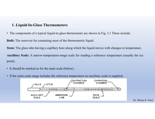
•The components of a typical liquid-in-glass thermometer are shown in Fig. 2.1 These include:
Bulb: The reservoir for containing most of the thermometric liquid.
Stem: The glass tube having a capillary bore along which the liquid moves with changes in temperature.
Auxiliary Scale: A narrow-temperature-range scale for reading a reference temperature (usually the ice
point).
• It should be marked as for the main scale (below).
• If the main scale range includes the reference temperature no auxiliary scale is supplied.
Dr. Dhiren R. Patel
5.
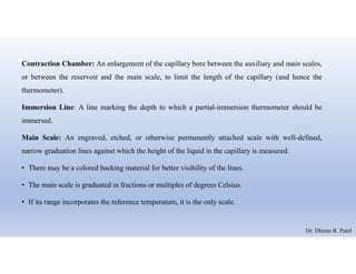
Contraction Chamber: Anenlargement of the capillary bore between the auxiliary and main scales,
or between the reservoir and the main scale, to limit the length of the capillary (and hence the
thermometer).
Immersion Line: A line marking the depth to which a partial-immersion thermometer should be
immersed.
Main Scale: An engraved, etched, or otherwise permanently attached scale with well-defined,
narrow graduation lines against which the height of the liquid in the capillary is measured.
• There may be a colored backing material for better visibility of the lines.
• The main scale is graduated in fractions or multiples of degrees Celsius.
• If its range incorporates the reference temperature, it is the only scale.
Dr. Dhiren R. Patel
6.
Expansion Chamber:
• Anenlargement at the top of the capillary into which the liquid can flow if the thermometer
temperature exceeds the scale limit.
• It is undesirable for liquid to enter the expansion chamber, however, so it is much better to ensure
that there is no overheating of the thermometer.
• The expansion chamber also prevents excessive gas pressure when the thermometer is used near
the top of its range, especially in high-temperature pressurized thermometers.
Dr. Dhiren R. Patel
7.
• The unitconsists of a glass envelope, a responsive liquid and an indicating scale.
• The envelope comprises a thick wailed glass tube with a capillary bore, and a spherical or cylindrical bulb filled with
the liquid.
• The two parts are fused together and the top end of the capillary tube is sealed.
• The range of a liquid-in-glass thermometer is limited by the liquid, by the glass, and by the construction.
• The commonest and best liquid is mercury.
• The recommended range of use is from near the mercury freezing point (-38 °C) to about 350 °C with soda-lime
glasses; higher temperatures require borosilicate or other special glasses.
• The capillary above the mercury is filled with a dry gas (frequently nitrogen) to prevent separation of the column and
to inhibit distillation of the mercury; in the higher-temperature models, substantial gas pressures are required to raise
the mercury boiling point above the range of the thermometer.
• Air is not a good filling gas because it may lead to oxidation of the mercury and consequent sticking of the latter in the
capillary. Dr. Dhiren R. Patel
8.
Working
• Changes inthe temperature will cause the fluid to expand and rise up the stem.
• Since the area of the stem is much less than the bulb, the respectively small changes of fluid volume will
result in significant fluid rise in the stem.
• The length of the movement of the free surface of the fluid column serves, by a prior calibration, to indicate
the temperature of the bulb.
• The laboratory work thermometers have a scale engraved directly on the glass stem, while the industry types
have separate scale located adjacent to the stem.
• Quite often the top of the capillary tube is also bulb shaped to provide safety in case the temperature range
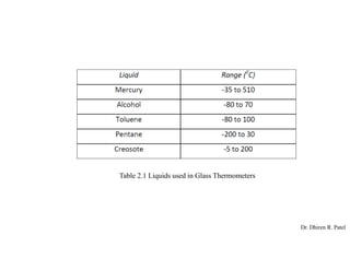
of the instrument is inadvertently exceeded. The range of application of different liquids is stated in table 2.1
Dr. Dhiren R. Patel
Salient features /characteristics:
Simplicity of use and relatively low cost easily pot table
Ease of checking for physical damage
Absence of need for auxiliary power
No need of additional indicating instruments
Fragile construction; range limited to about 600°C
Lack of adaptability to remote reading
Time lag between change of temperature and thermometer response due to relatively high heat capacity
of the bulb.
Dr. Dhiren R. Patel
11.
CALIBRATION OF THERMOMETER
•These thermometers are generally designed and calibrated for one of the following three conditions
shown in Fig. 2.2.
A. Total immersion — the bulb and liquid containing part of the capillary is exposed to the temperature
being measured.
B. Complete immersion — the entire thermometer is exposed to the temperature being measured.
C. Partial immersion — the liquid in the stem emerging from the liquid bath is subjected to the ambient
temperature which may be radically different from the temperature of the liquid bath.
Dr. Dhiren R. Patel
12.
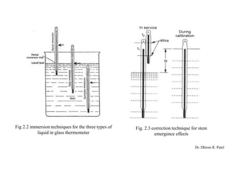
Fig 2.2 immersiontechniques for the three types of
liquid in glass thermometer
Fig. 2.3 correction technique for stem
emergence effects
Dr. Dhiren R. Patel
13.
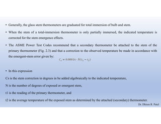
• Generally, theglass stem thermometers are graduated for total immersion of bulb and stem.
• When the stem of a total-immersion thermometer is only partially immersed, the indicated temperature is
corrected for the stem emergence effects.
• The ASME Power Test Codes recommend that a secondary thermometer be attached to the stem of the
primary thermometer (Fig. 2.3) and that a correction to the observed temperature be made in accordance with
the emergent-stem error given by:
• In this expression
Cs is the stem correction in degrees in be added algebraically to the indicated temperature,
N is the number of degrees of exposed or emergent stem,
t1 is the reading of the primary thermometer, and
t2 is the average temperature of the exposed stem as determined by the attached (secondary) thermometer.
Dr. Dhiren R. Patel
14.
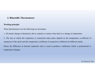
2. Bimetallic Thermometer
Workingprinciple
These thermometers use the following two principles:
1. All metals change in dimension, that is expand or contract when there is a change in temperature.
2. The rate at which this expansion or contraction takes place depend on the temperature co-efficient of
expansion of the metal and this temperature coefficient of expansion is different for different metals.
Hence the difference in thermal expansion rates is used to produce a deflection which is proportional to
temperature changes.
Dr. Dhiren R. Patel
15.
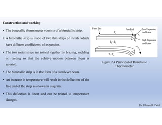
Construction and working
•The bimetallic thermometer consists of a bimetallic strip.
• A bimetallic strip is made of two thin strips of metals which
have different coefficients of expansion.
• The two metal strips are joined together by brazing, welding
or riveting so that the relative motion between them is
arrested.
• The bimetallic strip is in the form of a cantilever beam.
• An increase in temperature will result in the deflection of the
free end of the strip as shown in diagram.
• This deflection is linear and can be related to temperature
changes.
Figure 2.4 Principal of Bimetallic
Thermometer
Dr. Dhiren R. Patel
16.
• The radiusof the curvature of the bimetallic strip which was initially flat is determined using the following
relationship.
Where,
R = radius of the curvature at the temperature T2.
T = total thickness of the bimetallic strip = (t1+t2)
m = t1/t2 = ratio of thickness of low to high expansion materials,
α1 = coefficient of expansion of lower expansion metal.
α2 = coefficient of expansion of higher expansion metal.
T1 = Initial temperature.
T2 = temperature to be measured.
Dr. Dhiren R. Patel
17.
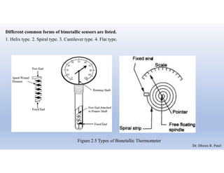
Different common formsof bimetallic sensors are listed.
1. Helix type. 2. Spiral type. 3. Cantilever type. 4. Flat type.
Figure 2.5 Types of Bimetallic Thermometer
Dr. Dhiren R. Patel
18.
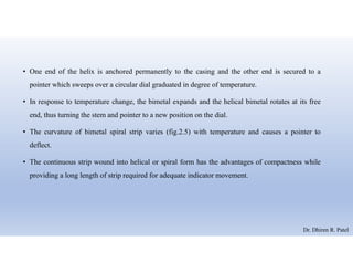
• One endof the helix is anchored permanently to the casing and the other end is secured to a
pointer which sweeps over a circular dial graduated in degree of temperature.
• In response to temperature change, the bimetal expands and the helical bimetal rotates at its free
end, thus turning the stem and pointer to a new position on the dial.
• The curvature of bimetal spiral strip varies (fig.2.5) with temperature and causes a pointer to
deflect.
• The continuous strip wound into helical or spiral form has the advantages of compactness while
providing a long length of strip required for adequate indicator movement.
Dr. Dhiren R. Patel
19.
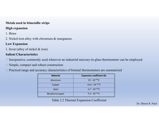
Metals used inbimetallic strips
High expansion
1. Brass
2. Nickel-iron alloy with chromium & manganese.
Low Expansion
1. Invar (alloy of nickel & iron).
Salient Characteristics
Inexpensive; commonly used wherever an industrial mercury-in-glass thermometer can be employed
Simple, compact and robust construction
Practical range and accuracy characteristics of bimetal thermometers are summarized
Table 2.2 Thermal Expansion Coefficient
Dr. Dhiren R. Patel
20.
3. THERMISTORS
Construction andworking
• Thermistor is a contraction of term “Thermal Resistor’.
• They are essentially semiconductors which behave as registers with a high negative temperature
coefficient.
• As the temperature increases, the resistance goes up.
• This is just opposite to the effect of temperature changes on metals.
• A high sensitivity to temperature changes (decrease in resistance as much as 6% for each 1°C rise in
temperature in some cases) makes the thermistors extremely useful for precision temperature
measurement, control and compensation in the temperature range of - 100°C to 300°C.
Dr. Dhiren R. Patel
21.
• The thermistorsare composed of metal oxides.
• The most commonly used oxides are those of manganese, nickel, cobalt, iron, copper and titanium.
• The fabrication of commercial NTC thermistors uses basic ceramics technology and continues today
much as it has for decades.
• In the basic process, a mixture of two or more metal oxide powders are combined with suitable binders,
are formed to a desired geometry, dried, and sintered at an elevated temperature.
• By varying the types of oxides used, their relative proportions, the sintering atmosphere, and the
sintering temperature, a wide range of resistivity and temperature coefficient characteristics can be
obtained.
• Metalized surface contact thermistors include the following:
Bead Disks Chips (Wafers) Rods
Dr. Dhiren R. Patel
22.
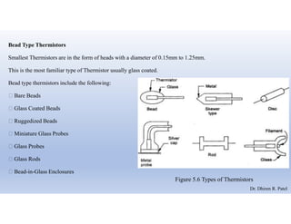
Bead Type Thermistors
SmallestThermistors are in the form of heads with a diameter of 0.15mm to 1.25mm.
This is the most familiar type of Thermistor usually glass coated.
Bead type thermistors include the following:
Bare Beads
Glass Coated Beads
Ruggedized Beads
Miniature Glass Probes
Glass Probes
Glass Rods
Bead-in-Glass Enclosures
Figure 5.6 Types of Thermistors
Dr. Dhiren R. Patel
23.
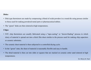
Disks:
• Disk typethermistors are made by compressing a blend of oxide powders in a round die using presses similar
to those used for making powdered metal parts or pharmaceutical tablets.
• The “green” disks are then sintered at high temperatures.
Chips:
• NTC chip thermistors are usually fabricated using a “tape-casting” or “doctor-blading” process in which
slurry of material is spread out into a thick film sheet similar to the process used for making chip capacitors
or ceramic substrates.
• The ceramic sheet material is then subjected to a controlled drying cycle.
• In the “green” state, the sheet of material is reasonably flexible and easy to handle.
• The dried material is then cut into slabs or squares that are stacked on ceramic setter sand sintered at high
temperatures.
Dr. Dhiren R. Patel
24.
Rods:
• Rod-type thermistorsare made by extruding a mixture of oxide powders and a suitable binder through a
die.
• Their greater mass, longer thermal time constants and higher dissipation constants makes them suitable for
applications involving temperature compensation, time delay or surge suppression.
Washers:
• Washer type thermistors are fabricated using techniques similar to those used for disks except that a hole is
formed in the center during the pressing operation.
• Washers are usually connected to circuitry by means of spring clips or other hardware.
Dr. Dhiren R. Patel