SlideShare a Scribd company logo
1 of 1
Download to read offline
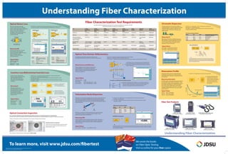
Understanding Fiber Characterization
Note: Specifications, terms and conditions are subject to change without notice.
30137200 004 0811 FIBERCHAR.PO.FOP.TM.AE
To learn more, visit www.jdsu.com/fibertest
Fiber Test Products
Cleaning connectors is important.
A dirty connector will dramatically increase power loss!
Inspect connectors before and after cleaning using a
video inspection scope.
Optical Connection Inspection
Before cleaning After cleaning
IEC 60512-25-2 – Connectors for electronic equipment – Tests and measurements
Part 25-2: Test 25b- Attenuation (insertion loss)
IEC 61300-3-34 – Fiber optic interconnecting devices and passive components Basic
test and measurement
ITU-T G650.1 – Definitions and test methods for linear, deterministic attributes of single-
mode fibre and cable
–
–
Power Meter Light Source
FUT Insertion loss is typically tested
using a power meter and a
2- or 3-wavelength light source.
FUT
Power Meter/
Light Source
Power Meter/
Light Source
Automatic bidirectional
insertion loss is tested using
a loss test set that combines a
light source and power meter.
Mechanical splice: 0.5 dB
Fusion splice: 0.1 dB
PC connector: 0.3 dB
APC connector: 0.5 dB
Typical Values
Measuring IL
1260 nm – 1360 nm:0.35 dB/km
1530 nm – 1565 nm:0.22 dB/km
1565 nm – 1625 nm:0.25 dB/km
IEC 60793-1-40 – Measurement methods and test procedures
FUT Optical
Spectrum
Analyzer
Broadband
Source
Wavelength (nm)
Water peak around 1383 nm
8500
1
10
1310 1550
Attenuation(dB/km)
Measuring Attenuation
Typical Values
Attenuation Profile
IEC 61786 – Calibration of optical time-domain reflectometers (OTDRs)
GR-196 – Generic Requirements for OTDR Type Equipment
ITU-T G650.1 – Definitions and test methods for linear, deterministic attributes of single-mode fiber and cable
OTDR
FUT
Coupler
Pulsed
Laser Source
Optical
Receiver
The OTDR injects a short, intense laser pulse into the optical fiber and
measures the backscatter and reflection of light as a function of time.
It then analyzes the information to determine the location of fiber optic
breaks or splice losses.
Fiber
End
Mechanical
Splice
Fiber
Bend
Connector
Pair
Fusion
Splice
Connector
Pair
Attenuation(dB)
OTDR
Splice loss
Splice gain
True Splice Loss: Bidirectional OTDR Measurement
The OTDR retrieves the fiber signature and distance and
loss/reflectance information for each event present along the link.
Mechanical splice: 0.5 dB
Fusion splice: 0.1 dB
UPC connector: Loss: 0.3 dB, Reflectance: −55 dB
APC connector: Loss: 0.5 dB, Reflectance: −65 dB
Typical Values
Measuring Loss and Reflectance
Optical Time Domain eflectometryR
Chromatic dispersion (CD) results from different
wavelengths (colors or spectral components of light)
traveling at different speeds in a fiber due to the
variation of index of refraction, including a pulse
width variation.
Distance
IEC 60793-1-42 – Optical fibers − Part 1-42: Measurement methods and
Chromatic dispersion
ITU-T G650.1 – Definitions and test methods for linear, deterministic attributes
of single-mode fiber and cable
test procedures –
Measuring CD
Typical Values
ITU-T G.652:~17 ps/(nm.km) at 1550 nm
ITU-T G.653: 0 ps/(nm.km) at 1550 nm
ITU-T G.655: ~4 ps/(nm.km) at 1550 nm
The modulated light is sent over the FUT. The phase of the test signal is
compared to the phase of the reference signal used to modulate the input
signal. The phase measurement is performed over the entire wavelength
range of the broadband source.
Phase Shift Method
FUT
Phase Meter
Broadband
Source
Intensity
Modulator
∆φ
Phase Shift
λref
λ
CD Limits According to Bit Rate
Chromatic Dispersion
Bit Rate SDH SONET Total Allowable Dispersion
at 1550 nm
Coefficient
for a Given Link
2.5 Gbps STM-16 OC-48 12000 to 16000 ps/nm
10 Gbps STM-64 OC-192 800 to 1000 ps/nm
40 Gbps STM-256 OC-768 60 to 100 ps/nm
10 Gbps Ethernet 738 ps/nm—
PMD Limits According to Bit Rate
IEC 60793-1-48 – Optical fibers - Part 1-48: Measurement methods and test procedures –
polarization mode dispersion
ITU-T G650.2 – Definitions and test methods for statistical and nonlinear attributes of single-
mode fiber and cable
V2
V1
DGD
Field PMD Test Equipment
Polarzized
Broadband Source
FUT Optical
Spectrum
Analyzer
Send a polarized light over the FUT to enable analysis of the transmitted spectrum through a polarizer. The analysis
of the fixed-analyzer response is shifted to the time domain by taking the Fourier transform. Calculate mean DGD
from the Gaussian distribution.For a new fiber - Max PMD: 0.2 ps/√kmITU-T G.652D
Typical Values
Measuring PMD
Polarization Mode Dispersion
Bit Rate SDH SONET PMD
Per Channel Delay Limit
2.5 Gbps STM-16 OC-48 40 ps
10 Gbps STM-64 OC-192 10 ps
40 Gbps STM-256 OC-768 2.5 ps
10 Gbps Ethernet - 5 ps
Use a connector inspection scope to guarantee that optical connectors are operational and free of contamination.
Particles, such as dust, are the primary source of problems in optical networks causing backreflection, signal loss, and equipment damage.
Mating contaminated connectors embeds debris into the glass causing permanent damage.
Fiber connectors should always be visually inspected before mating!
SmartClass™ Family
Optical Handheld Meters
T-BERD®/MTS-4000
Multiple Services Test Platform
P5000i Digital Analysis Microscope
Optical Video Inspection Probe
Scalable Optical Test Platform
T-BERD®/MTS-8000E
Test 2.5 Gbps 2.5 Gpbs 10 Gbps 10 Gbps 40 Gbps Equipment Testing
STM-16/OC-48 STM-16/OC-48 STM-64/OC-192 STM-64/OC-192 STM-256/OC-768 Required Recommended
1550 DWDM 1550 DWDM DWDM
Insertion Loss LTS
Return Loss
Physical PlantVerification
Polarization Mode
Chromatic Dispersion
10 Gbps
Ethernet
Dispersion
Attenuation Profile
1310/1550 nm 1550/1625 nm 1310/1550 nm 1550/1625 nm 1310/1550/1625 nm 1310/1550 nm PM & LS, or Unidirectional
1550 nm 1550 nm 1550 nm 1550 nm 1550 nm 1550 nm OTDR or ORL Meter Unidirectional
1310/1550 nm 1550/1625 nm 1310/1550 nm 1550/1625 nm 1310/1550 nm 1310/1550 nm 2 or 3 wavelengths Bidirectional
<80 km not required <80 km not required Required Required Required Required BB Source, Unidirectional
Not required if less Not required if less Recommended Recommended Recommended Recommended 4 Lambda OTDR or Unidirectional
( OTDR
)
unless pre-1993 fiber unless pre-1993 fiber PMD Analyzer
than150 km than 150 km Phase Shift Analyzer
No 1550 to 1625 nm No 1550 to 1625 nm 1550 to 1625 nm 1550 to 1625 nm BB Source and OSA Unidirectional
Inc. Connector & Splice Loss/
Point Ref. / Distance
Fiber Characterization Test Requirements
This table is greatly simplified and each user must review and modify it in accordance with their
specific Network Element equipment and application.IEC 61300-3-6 – Fiber optic interconnecting devices and passive components – Basic
test and measurement – Part 3-6: Examinations and measurements – Return loss
ORL = 10 log (P /P )inc refl
PtransP inc
Prefl
Optical Component
(e.g. connector)
ORL is the ratio (expressed in dB)
between incident power and reflective
power in a fiber optic network. The reflected
power is due to Fresnel reflections or
changes in the index of refraction.
The higher the ORL value, the lower the
reflected power, therefore, 40 dB
is better than 30 dB.
Measuring backreflection is essential
when installing and maintaining
networks, especially in DWDM or analog
CATV transmission systems.
High levels of ORL will decrease
system performance.
OCWR Method
OCWR
FUT
Coupler
Termination
Plug
Light Source
Optical
Power Meter
The OCWR launches a stable, continuous wave
signal into the optical fiber and measures the
strength of the time-integrated return signal.
Accuracy: ± 0.5 dB
Typ. Appl.: Total link ORL
Strengths: Accurate
Fast and real time information
Possibility to measure short link
Weaknesses: No reflective event localization
OTDR Method
OTDR
FUT
Coupler
Pulsed
Laser Source
Optical
Receiver
The OTDR launches light pulses into the device
under test and collects backscatter information
as well as Fresnel reflections.
Accuracy: ±2 dB
Typ. Appl.: Spatial characterization of reflective
events & estimation of sectional and
total link ORL
Strength: Reflective event localization
Weaknesses: Accuracy
Longer acquisition time
Requirement: 27 dB
Objective: 40 dB
(defined by Telcordia
GR-1312-CORE)
Typical Values
Measuring ORL
Optical Return Loss
Understanding Fiber Characterization
Insertion Loss/Bidirectional Insertion Loss
We wrote the books
on Fiber Optic Testing.
Visit us online for your free copies.
Fiber Optic Testing
Volume 2
Insertion Loss (IL) represents the
decrease of power (expressed in dB)
when optical light path travels
down a fiber link through passive
components, such as connectors
and splices.
Measuring insertion loss is
extremely important because each
transmitter/receiver combination
has a limited power range.
Exceeding these limitations can
result in transmission failure or
excessive noise.
PMD refers to the temporal spreading of the transmission signal pulses due to
birefringence resulting from the differential time delay between principal
states of polarization (PSPs) of the fiber. Two PSPs propagating at different
speeds through the fiber may cause severe distortion in the optical receiver at
the end of the fiber.
PMD may vary with time and with optical frequency, therefore, signals
transmitted over different wavelength channels of a fiber usually
experience varying amounts of distortion.
Measuring PMD during the manufacturing process, fiber installation, or
system upgrades ensures that the fiber link is suitable for high-speed
transmissions of 10 Gbps or higher and within network equipment or
system constraints.
Test spectral attenuation using a
broadband source and optical
spectrum analyzer. The spectrum
analyzer compares the broadband
source reference signal to the
resulting signal at the end of the
fiber under test.
In DWDM systems, obtaining the attenuation profile of
the wavelength range used for transmission is impor-
tant because it impacts channel equalization as well as
the amplifier specifications for equipment placed in
the network. Check CWDM systems, covering the
entire wavelength range of 1261 to 1611 nm, for fiber
suitability, especially within the“water peak”region
around 1383 nm.
Attenuation profile is the loss of signal power per
wavelength, normalized to 1 km, and is caused by
material absorption, impurities, waveguide geometry,
and scattering.
Measuring CD during the manufacturing process,
fiber installation, or system upgrades ensures that
the fiber link is suitable for high-speed transmis-
sions of 10 Gbps or higher and within network
equipment or system constraints.
Testing components, such as splices and connectors,
during installation or commissioning is important
because their losses and reflectances greatly impact link
quality. An OTDR can detect, localize, and measure
events along a fiber link.
Mismatches in fiber backscatter coefficients can cause a splice to appear as a
gain or a loss, depending upon the test direction. Use of bidirectional analysis
removes the effects of mismatches by measuring the splice loss in both
directions and averaging the result to obtain the true splice loss.
T-BERD®/MTS-6000
Compact Optical Test Platform
T-BERD®/MTS-2000
Compact Optical Test Platform

More Related Content

What's hot

TCP/IP performance over Optical Fiber
TCP/IP performance over Optical FiberTCP/IP performance over Optical Fiber
TCP/IP performance over Optical FiberShethwala Ridhvesh
 
Fiber otdr testing
Fiber otdr testingFiber otdr testing
Fiber otdr testingbsateeshbsnl
 
OTDR(OPTICAL TIME DOMAIN REFLECTOMETER)
OTDR(OPTICAL TIME DOMAIN REFLECTOMETER)OTDR(OPTICAL TIME DOMAIN REFLECTOMETER)
OTDR(OPTICAL TIME DOMAIN REFLECTOMETER)Shail Mishra
 
Analog and digital modulation formats of optical fiber communication within a...
Analog and digital modulation formats of optical fiber communication within a...Analog and digital modulation formats of optical fiber communication within a...
Analog and digital modulation formats of optical fiber communication within a...IAEME Publication
 
3-WE3_ExtendingTheReachOfVCSEL_Rev5
3-WE3_ExtendingTheReachOfVCSEL_Rev53-WE3_ExtendingTheReachOfVCSEL_Rev5
3-WE3_ExtendingTheReachOfVCSEL_Rev5Waruna Fernando
 
Measuring Fiber / Merenja na optičkim vlaknima
Measuring Fiber / Merenja na optičkim vlaknimaMeasuring Fiber / Merenja na optičkim vlaknima
Measuring Fiber / Merenja na optičkim vlaknimaNemanja Radić
 
Introduction to RF & Wireless - Part 1
Introduction to RF & Wireless - Part 1Introduction to RF & Wireless - Part 1
Introduction to RF & Wireless - Part 1Carl Weisman
 
Process Variation Aware Crosstalk Mitigation for DWDM based Photonic NoC Arch...
Process Variation Aware Crosstalk Mitigation for DWDM based Photonic NoC Arch...Process Variation Aware Crosstalk Mitigation for DWDM based Photonic NoC Arch...
Process Variation Aware Crosstalk Mitigation for DWDM based Photonic NoC Arch...Ishan Thakkar
 
Fundamentals of RF Systems
Fundamentals of RF SystemsFundamentals of RF Systems
Fundamentals of RF SystemsYong Heui Cho
 
Cisco DWDM Chromatic Dispertion Calculation in CTP\XLS
Cisco DWDM Chromatic Dispertion Calculation in CTP\XLSCisco DWDM Chromatic Dispertion Calculation in CTP\XLS
Cisco DWDM Chromatic Dispertion Calculation in CTP\XLSValery Kayukov
 
Polymer Waveguide Based Optical Interconnects for High-Speed On-Board Communi...
Polymer Waveguide Based Optical Interconnects for High-Speed On-Board Communi...Polymer Waveguide Based Optical Interconnects for High-Speed On-Board Communi...
Polymer Waveguide Based Optical Interconnects for High-Speed On-Board Communi...Jian Chen
 
OPTICAL TIME DOMAIN REFLECTOMETRY-OTDR
OPTICAL TIME DOMAIN REFLECTOMETRY-OTDROPTICAL TIME DOMAIN REFLECTOMETRY-OTDR
OPTICAL TIME DOMAIN REFLECTOMETRY-OTDRPremashis Kumar
 

What's hot (20)

APD & Laser Diode
APD & Laser Diode APD & Laser Diode
APD & Laser Diode
 
Optical Time Domain Reflector
Optical Time Domain ReflectorOptical Time Domain Reflector
Optical Time Domain Reflector
 
TCP/IP performance over Optical Fiber
TCP/IP performance over Optical FiberTCP/IP performance over Optical Fiber
TCP/IP performance over Optical Fiber
 
Optical receivers
Optical receiversOptical receivers
Optical receivers
 
Fiber otdr testing
Fiber otdr testingFiber otdr testing
Fiber otdr testing
 
OTDR(OPTICAL TIME DOMAIN REFLECTOMETER)
OTDR(OPTICAL TIME DOMAIN REFLECTOMETER)OTDR(OPTICAL TIME DOMAIN REFLECTOMETER)
OTDR(OPTICAL TIME DOMAIN REFLECTOMETER)
 
Analog and digital modulation formats of optical fiber communication within a...
Analog and digital modulation formats of optical fiber communication within a...Analog and digital modulation formats of optical fiber communication within a...
Analog and digital modulation formats of optical fiber communication within a...
 
Basics of RF
Basics of RFBasics of RF
Basics of RF
 
3-WE3_ExtendingTheReachOfVCSEL_Rev5
3-WE3_ExtendingTheReachOfVCSEL_Rev53-WE3_ExtendingTheReachOfVCSEL_Rev5
3-WE3_ExtendingTheReachOfVCSEL_Rev5
 
Measuring Fiber / Merenja na optičkim vlaknima
Measuring Fiber / Merenja na optičkim vlaknimaMeasuring Fiber / Merenja na optičkim vlaknima
Measuring Fiber / Merenja na optičkim vlaknima
 
Introduction to RF & Wireless - Part 1
Introduction to RF & Wireless - Part 1Introduction to RF & Wireless - Part 1
Introduction to RF & Wireless - Part 1
 
Process Variation Aware Crosstalk Mitigation for DWDM based Photonic NoC Arch...
Process Variation Aware Crosstalk Mitigation for DWDM based Photonic NoC Arch...Process Variation Aware Crosstalk Mitigation for DWDM based Photonic NoC Arch...
Process Variation Aware Crosstalk Mitigation for DWDM based Photonic NoC Arch...
 
Rf basics
Rf basicsRf basics
Rf basics
 
Bg25346351
Bg25346351Bg25346351
Bg25346351
 
Ch17
Ch17Ch17
Ch17
 
Fundamentals of RF Systems
Fundamentals of RF SystemsFundamentals of RF Systems
Fundamentals of RF Systems
 
Cisco DWDM Chromatic Dispertion Calculation in CTP\XLS
Cisco DWDM Chromatic Dispertion Calculation in CTP\XLSCisco DWDM Chromatic Dispertion Calculation in CTP\XLS
Cisco DWDM Chromatic Dispertion Calculation in CTP\XLS
 
RF module
RF moduleRF module
RF module
 
Polymer Waveguide Based Optical Interconnects for High-Speed On-Board Communi...
Polymer Waveguide Based Optical Interconnects for High-Speed On-Board Communi...Polymer Waveguide Based Optical Interconnects for High-Speed On-Board Communi...
Polymer Waveguide Based Optical Interconnects for High-Speed On-Board Communi...
 
OPTICAL TIME DOMAIN REFLECTOMETRY-OTDR
OPTICAL TIME DOMAIN REFLECTOMETRY-OTDROPTICAL TIME DOMAIN REFLECTOMETRY-OTDR
OPTICAL TIME DOMAIN REFLECTOMETRY-OTDR
 

Similar to Understanding fiber-characterization-po-fop-tm-ae

SPC_EXFOSession1.pdf
SPC_EXFOSession1.pdfSPC_EXFOSession1.pdf
SPC_EXFOSession1.pdfmenif73
 
09-Luna-Fiber-Optic-Test-Measurement-final.pptx
09-Luna-Fiber-Optic-Test-Measurement-final.pptx09-Luna-Fiber-Optic-Test-Measurement-final.pptx
09-Luna-Fiber-Optic-Test-Measurement-final.pptxAbdalmoedAlaiashy2
 
Transmission system used for optical fibers
Transmission system used for optical fibers Transmission system used for optical fibers
Transmission system used for optical fibers Jay Baria
 
Fiber Optic Measurement.pdf
Fiber Optic Measurement.pdfFiber Optic Measurement.pdf
Fiber Optic Measurement.pdfmengistuyirga
 
OTDR HSV600 User Training.pptx
OTDR HSV600 User Training.pptxOTDR HSV600 User Training.pptx
OTDR HSV600 User Training.pptxNatalie Felicerta
 
Testing effectiveness of the splice through otdr and power meter tests
Testing effectiveness of the splice through otdr and  power meter testsTesting effectiveness of the splice through otdr and  power meter tests
Testing effectiveness of the splice through otdr and power meter testsBala V
 
Optical_Fiber_Technology
Optical_Fiber_TechnologyOptical_Fiber_Technology
Optical_Fiber_Technologyrajen maji
 
Fiber Optical Cable illustrated Presentation.ppt
Fiber Optical Cable illustrated Presentation.pptFiber Optical Cable illustrated Presentation.ppt
Fiber Optical Cable illustrated Presentation.pptAbdalmoedAlaiashy2
 
101483423-Fiber-Characterization-Training.pdf
101483423-Fiber-Characterization-Training.pdf101483423-Fiber-Characterization-Training.pdf
101483423-Fiber-Characterization-Training.pdfMohamedshabana38
 
OFC link design and WDM network
OFC link design and WDM network OFC link design and WDM network
OFC link design and WDM network ashok mane
 
Nd At S Best Practices For Single Mode Tier I Ii Testing 01 2011
Nd At S   Best Practices For Single Mode Tier I  Ii Testing 01 2011Nd At S   Best Practices For Single Mode Tier I  Ii Testing 01 2011
Nd At S Best Practices For Single Mode Tier I Ii Testing 01 2011Dean Murray
 
Optical fiber communication-Presented by Kiran Devkota
Optical fiber communication-Presented by Kiran DevkotaOptical fiber communication-Presented by Kiran Devkota
Optical fiber communication-Presented by Kiran DevkotaSujit Jha
 
Optical Fibres by using Digital Communication without Direct Current to Detec...
Optical Fibres by using Digital Communication without Direct Current to Detec...Optical Fibres by using Digital Communication without Direct Current to Detec...
Optical Fibres by using Digital Communication without Direct Current to Detec...IRJET Journal
 
foc Unit 5 point -to- point link system conc.pptx
foc Unit 5 point -to- point link system conc.pptxfoc Unit 5 point -to- point link system conc.pptx
foc Unit 5 point -to- point link system conc.pptxhari341507
 
ComNet FDC1M Data Sheet
ComNet FDC1M Data SheetComNet FDC1M Data Sheet
ComNet FDC1M Data SheetJMAC Supply
 

Similar to Understanding fiber-characterization-po-fop-tm-ae (20)

SPC_EXFOSession1.pdf
SPC_EXFOSession1.pdfSPC_EXFOSession1.pdf
SPC_EXFOSession1.pdf
 
Optical fiber
Optical fiber   Optical fiber
Optical fiber
 
09-Luna-Fiber-Optic-Test-Measurement-final.pptx
09-Luna-Fiber-Optic-Test-Measurement-final.pptx09-Luna-Fiber-Optic-Test-Measurement-final.pptx
09-Luna-Fiber-Optic-Test-Measurement-final.pptx
 
Transmission system used for optical fibers
Transmission system used for optical fibers Transmission system used for optical fibers
Transmission system used for optical fibers
 
H010315456
H010315456H010315456
H010315456
 
Fiber Optic Measurement.pdf
Fiber Optic Measurement.pdfFiber Optic Measurement.pdf
Fiber Optic Measurement.pdf
 
OTDR HSV600 User Training.pptx
OTDR HSV600 User Training.pptxOTDR HSV600 User Training.pptx
OTDR HSV600 User Training.pptx
 
Testing effectiveness of the splice through otdr and power meter tests
Testing effectiveness of the splice through otdr and  power meter testsTesting effectiveness of the splice through otdr and  power meter tests
Testing effectiveness of the splice through otdr and power meter tests
 
Optical_Fiber_Technology
Optical_Fiber_TechnologyOptical_Fiber_Technology
Optical_Fiber_Technology
 
OTDR Testing
OTDR TestingOTDR Testing
OTDR Testing
 
Fiber Optics
Fiber OpticsFiber Optics
Fiber Optics
 
Fiber Optical Cable illustrated Presentation.ppt
Fiber Optical Cable illustrated Presentation.pptFiber Optical Cable illustrated Presentation.ppt
Fiber Optical Cable illustrated Presentation.ppt
 
101483423-Fiber-Characterization-Training.pdf
101483423-Fiber-Characterization-Training.pdf101483423-Fiber-Characterization-Training.pdf
101483423-Fiber-Characterization-Training.pdf
 
OFC link design and WDM network
OFC link design and WDM network OFC link design and WDM network
OFC link design and WDM network
 
Nd At S Best Practices For Single Mode Tier I Ii Testing 01 2011
Nd At S   Best Practices For Single Mode Tier I  Ii Testing 01 2011Nd At S   Best Practices For Single Mode Tier I  Ii Testing 01 2011
Nd At S Best Practices For Single Mode Tier I Ii Testing 01 2011
 
Cma5000a osa
Cma5000a   osaCma5000a   osa
Cma5000a osa
 
Optical fiber communication-Presented by Kiran Devkota
Optical fiber communication-Presented by Kiran DevkotaOptical fiber communication-Presented by Kiran Devkota
Optical fiber communication-Presented by Kiran Devkota
 
Optical Fibres by using Digital Communication without Direct Current to Detec...
Optical Fibres by using Digital Communication without Direct Current to Detec...Optical Fibres by using Digital Communication without Direct Current to Detec...
Optical Fibres by using Digital Communication without Direct Current to Detec...
 
foc Unit 5 point -to- point link system conc.pptx
foc Unit 5 point -to- point link system conc.pptxfoc Unit 5 point -to- point link system conc.pptx
foc Unit 5 point -to- point link system conc.pptx
 
ComNet FDC1M Data Sheet
ComNet FDC1M Data SheetComNet FDC1M Data Sheet
ComNet FDC1M Data Sheet
 

Recently uploaded

Understanding the Laravel MVC Architecture
Understanding the Laravel MVC ArchitectureUnderstanding the Laravel MVC Architecture
Understanding the Laravel MVC ArchitecturePixlogix Infotech
 
How to convert PDF to text with Nanonets
How to convert PDF to text with NanonetsHow to convert PDF to text with Nanonets
How to convert PDF to text with Nanonetsnaman860154
 
Advanced Test Driven-Development @ php[tek] 2024
Advanced Test Driven-Development @ php[tek] 2024Advanced Test Driven-Development @ php[tek] 2024
Advanced Test Driven-Development @ php[tek] 2024Scott Keck-Warren
 
Swan(sea) Song – personal research during my six years at Swansea ... and bey...
Swan(sea) Song – personal research during my six years at Swansea ... and bey...Swan(sea) Song – personal research during my six years at Swansea ... and bey...
Swan(sea) Song – personal research during my six years at Swansea ... and bey...Alan Dix
 
Unlocking the Potential of the Cloud for IBM Power Systems
Unlocking the Potential of the Cloud for IBM Power SystemsUnlocking the Potential of the Cloud for IBM Power Systems
Unlocking the Potential of the Cloud for IBM Power SystemsPrecisely
 
My Hashitalk Indonesia April 2024 Presentation
My Hashitalk Indonesia April 2024 PresentationMy Hashitalk Indonesia April 2024 Presentation
My Hashitalk Indonesia April 2024 PresentationRidwan Fadjar
 
#StandardsGoals for 2024: What’s new for BISAC - Tech Forum 2024
#StandardsGoals for 2024: What’s new for BISAC - Tech Forum 2024#StandardsGoals for 2024: What’s new for BISAC - Tech Forum 2024
#StandardsGoals for 2024: What’s new for BISAC - Tech Forum 2024BookNet Canada
 
Key Features Of Token Development (1).pptx
Key  Features Of Token  Development (1).pptxKey  Features Of Token  Development (1).pptx
Key Features Of Token Development (1).pptxLBM Solutions
 
The Codex of Business Writing Software for Real-World Solutions 2.pptx
The Codex of Business Writing Software for Real-World Solutions 2.pptxThe Codex of Business Writing Software for Real-World Solutions 2.pptx
The Codex of Business Writing Software for Real-World Solutions 2.pptxMalak Abu Hammad
 
Scanning the Internet for External Cloud Exposures via SSL Certs
Scanning the Internet for External Cloud Exposures via SSL CertsScanning the Internet for External Cloud Exposures via SSL Certs
Scanning the Internet for External Cloud Exposures via SSL CertsRizwan Syed
 
Human Factors of XR: Using Human Factors to Design XR Systems
Human Factors of XR: Using Human Factors to Design XR SystemsHuman Factors of XR: Using Human Factors to Design XR Systems
Human Factors of XR: Using Human Factors to Design XR SystemsMark Billinghurst
 
APIForce Zurich 5 April Automation LPDG
APIForce Zurich 5 April  Automation LPDGAPIForce Zurich 5 April  Automation LPDG
APIForce Zurich 5 April Automation LPDGMarianaLemus7
 
Are Multi-Cloud and Serverless Good or Bad?
Are Multi-Cloud and Serverless Good or Bad?Are Multi-Cloud and Serverless Good or Bad?
Are Multi-Cloud and Serverless Good or Bad?Mattias Andersson
 
Presentation on how to chat with PDF using ChatGPT code interpreter
Presentation on how to chat with PDF using ChatGPT code interpreterPresentation on how to chat with PDF using ChatGPT code interpreter
Presentation on how to chat with PDF using ChatGPT code interpreternaman860154
 
Pigging Solutions Piggable Sweeping Elbows
Pigging Solutions Piggable Sweeping ElbowsPigging Solutions Piggable Sweeping Elbows
Pigging Solutions Piggable Sweeping ElbowsPigging Solutions
 
Maximizing Board Effectiveness 2024 Webinar.pptx
Maximizing Board Effectiveness 2024 Webinar.pptxMaximizing Board Effectiveness 2024 Webinar.pptx
Maximizing Board Effectiveness 2024 Webinar.pptxOnBoard
 
"Federated learning: out of reach no matter how close",Oleksandr Lapshyn
"Federated learning: out of reach no matter how close",Oleksandr Lapshyn"Federated learning: out of reach no matter how close",Oleksandr Lapshyn
"Federated learning: out of reach no matter how close",Oleksandr LapshynFwdays
 
AI as an Interface for Commercial Buildings
AI as an Interface for Commercial BuildingsAI as an Interface for Commercial Buildings
AI as an Interface for Commercial BuildingsMemoori
 

Recently uploaded (20)

08448380779 Call Girls In Diplomatic Enclave Women Seeking Men
08448380779 Call Girls In Diplomatic Enclave Women Seeking Men08448380779 Call Girls In Diplomatic Enclave Women Seeking Men
08448380779 Call Girls In Diplomatic Enclave Women Seeking Men
 
Understanding the Laravel MVC Architecture
Understanding the Laravel MVC ArchitectureUnderstanding the Laravel MVC Architecture
Understanding the Laravel MVC Architecture
 
How to convert PDF to text with Nanonets
How to convert PDF to text with NanonetsHow to convert PDF to text with Nanonets
How to convert PDF to text with Nanonets
 
Advanced Test Driven-Development @ php[tek] 2024
Advanced Test Driven-Development @ php[tek] 2024Advanced Test Driven-Development @ php[tek] 2024
Advanced Test Driven-Development @ php[tek] 2024
 
Swan(sea) Song – personal research during my six years at Swansea ... and bey...
Swan(sea) Song – personal research during my six years at Swansea ... and bey...Swan(sea) Song – personal research during my six years at Swansea ... and bey...
Swan(sea) Song – personal research during my six years at Swansea ... and bey...
 
Unlocking the Potential of the Cloud for IBM Power Systems
Unlocking the Potential of the Cloud for IBM Power SystemsUnlocking the Potential of the Cloud for IBM Power Systems
Unlocking the Potential of the Cloud for IBM Power Systems
 
My Hashitalk Indonesia April 2024 Presentation
My Hashitalk Indonesia April 2024 PresentationMy Hashitalk Indonesia April 2024 Presentation
My Hashitalk Indonesia April 2024 Presentation
 
#StandardsGoals for 2024: What’s new for BISAC - Tech Forum 2024
#StandardsGoals for 2024: What’s new for BISAC - Tech Forum 2024#StandardsGoals for 2024: What’s new for BISAC - Tech Forum 2024
#StandardsGoals for 2024: What’s new for BISAC - Tech Forum 2024
 
Key Features Of Token Development (1).pptx
Key  Features Of Token  Development (1).pptxKey  Features Of Token  Development (1).pptx
Key Features Of Token Development (1).pptx
 
The Codex of Business Writing Software for Real-World Solutions 2.pptx
The Codex of Business Writing Software for Real-World Solutions 2.pptxThe Codex of Business Writing Software for Real-World Solutions 2.pptx
The Codex of Business Writing Software for Real-World Solutions 2.pptx
 
Scanning the Internet for External Cloud Exposures via SSL Certs
Scanning the Internet for External Cloud Exposures via SSL CertsScanning the Internet for External Cloud Exposures via SSL Certs
Scanning the Internet for External Cloud Exposures via SSL Certs
 
Human Factors of XR: Using Human Factors to Design XR Systems
Human Factors of XR: Using Human Factors to Design XR SystemsHuman Factors of XR: Using Human Factors to Design XR Systems
Human Factors of XR: Using Human Factors to Design XR Systems
 
APIForce Zurich 5 April Automation LPDG
APIForce Zurich 5 April  Automation LPDGAPIForce Zurich 5 April  Automation LPDG
APIForce Zurich 5 April Automation LPDG
 
Are Multi-Cloud and Serverless Good or Bad?
Are Multi-Cloud and Serverless Good or Bad?Are Multi-Cloud and Serverless Good or Bad?
Are Multi-Cloud and Serverless Good or Bad?
 
Presentation on how to chat with PDF using ChatGPT code interpreter
Presentation on how to chat with PDF using ChatGPT code interpreterPresentation on how to chat with PDF using ChatGPT code interpreter
Presentation on how to chat with PDF using ChatGPT code interpreter
 
Pigging Solutions Piggable Sweeping Elbows
Pigging Solutions Piggable Sweeping ElbowsPigging Solutions Piggable Sweeping Elbows
Pigging Solutions Piggable Sweeping Elbows
 
Maximizing Board Effectiveness 2024 Webinar.pptx
Maximizing Board Effectiveness 2024 Webinar.pptxMaximizing Board Effectiveness 2024 Webinar.pptx
Maximizing Board Effectiveness 2024 Webinar.pptx
 
DMCC Future of Trade Web3 - Special Edition
DMCC Future of Trade Web3 - Special EditionDMCC Future of Trade Web3 - Special Edition
DMCC Future of Trade Web3 - Special Edition
 
"Federated learning: out of reach no matter how close",Oleksandr Lapshyn
"Federated learning: out of reach no matter how close",Oleksandr Lapshyn"Federated learning: out of reach no matter how close",Oleksandr Lapshyn
"Federated learning: out of reach no matter how close",Oleksandr Lapshyn
 
AI as an Interface for Commercial Buildings
AI as an Interface for Commercial BuildingsAI as an Interface for Commercial Buildings
AI as an Interface for Commercial Buildings
 

Understanding fiber-characterization-po-fop-tm-ae

  • 1. Understanding Fiber Characterization Note: Specifications, terms and conditions are subject to change without notice. 30137200 004 0811 FIBERCHAR.PO.FOP.TM.AE To learn more, visit www.jdsu.com/fibertest Fiber Test Products Cleaning connectors is important. A dirty connector will dramatically increase power loss! Inspect connectors before and after cleaning using a video inspection scope. Optical Connection Inspection Before cleaning After cleaning IEC 60512-25-2 – Connectors for electronic equipment – Tests and measurements Part 25-2: Test 25b- Attenuation (insertion loss) IEC 61300-3-34 – Fiber optic interconnecting devices and passive components Basic test and measurement ITU-T G650.1 – Definitions and test methods for linear, deterministic attributes of single- mode fibre and cable – – Power Meter Light Source FUT Insertion loss is typically tested using a power meter and a 2- or 3-wavelength light source. FUT Power Meter/ Light Source Power Meter/ Light Source Automatic bidirectional insertion loss is tested using a loss test set that combines a light source and power meter. Mechanical splice: 0.5 dB Fusion splice: 0.1 dB PC connector: 0.3 dB APC connector: 0.5 dB Typical Values Measuring IL 1260 nm – 1360 nm:0.35 dB/km 1530 nm – 1565 nm:0.22 dB/km 1565 nm – 1625 nm:0.25 dB/km IEC 60793-1-40 – Measurement methods and test procedures FUT Optical Spectrum Analyzer Broadband Source Wavelength (nm) Water peak around 1383 nm 8500 1 10 1310 1550 Attenuation(dB/km) Measuring Attenuation Typical Values Attenuation Profile IEC 61786 – Calibration of optical time-domain reflectometers (OTDRs) GR-196 – Generic Requirements for OTDR Type Equipment ITU-T G650.1 – Definitions and test methods for linear, deterministic attributes of single-mode fiber and cable OTDR FUT Coupler Pulsed Laser Source Optical Receiver The OTDR injects a short, intense laser pulse into the optical fiber and measures the backscatter and reflection of light as a function of time. It then analyzes the information to determine the location of fiber optic breaks or splice losses. Fiber End Mechanical Splice Fiber Bend Connector Pair Fusion Splice Connector Pair Attenuation(dB) OTDR Splice loss Splice gain True Splice Loss: Bidirectional OTDR Measurement The OTDR retrieves the fiber signature and distance and loss/reflectance information for each event present along the link. Mechanical splice: 0.5 dB Fusion splice: 0.1 dB UPC connector: Loss: 0.3 dB, Reflectance: −55 dB APC connector: Loss: 0.5 dB, Reflectance: −65 dB Typical Values Measuring Loss and Reflectance Optical Time Domain eflectometryR Chromatic dispersion (CD) results from different wavelengths (colors or spectral components of light) traveling at different speeds in a fiber due to the variation of index of refraction, including a pulse width variation. Distance IEC 60793-1-42 – Optical fibers − Part 1-42: Measurement methods and Chromatic dispersion ITU-T G650.1 – Definitions and test methods for linear, deterministic attributes of single-mode fiber and cable test procedures – Measuring CD Typical Values ITU-T G.652:~17 ps/(nm.km) at 1550 nm ITU-T G.653: 0 ps/(nm.km) at 1550 nm ITU-T G.655: ~4 ps/(nm.km) at 1550 nm The modulated light is sent over the FUT. The phase of the test signal is compared to the phase of the reference signal used to modulate the input signal. The phase measurement is performed over the entire wavelength range of the broadband source. Phase Shift Method FUT Phase Meter Broadband Source Intensity Modulator ∆φ Phase Shift λref λ CD Limits According to Bit Rate Chromatic Dispersion Bit Rate SDH SONET Total Allowable Dispersion at 1550 nm Coefficient for a Given Link 2.5 Gbps STM-16 OC-48 12000 to 16000 ps/nm 10 Gbps STM-64 OC-192 800 to 1000 ps/nm 40 Gbps STM-256 OC-768 60 to 100 ps/nm 10 Gbps Ethernet 738 ps/nm— PMD Limits According to Bit Rate IEC 60793-1-48 – Optical fibers - Part 1-48: Measurement methods and test procedures – polarization mode dispersion ITU-T G650.2 – Definitions and test methods for statistical and nonlinear attributes of single- mode fiber and cable V2 V1 DGD Field PMD Test Equipment Polarzized Broadband Source FUT Optical Spectrum Analyzer Send a polarized light over the FUT to enable analysis of the transmitted spectrum through a polarizer. The analysis of the fixed-analyzer response is shifted to the time domain by taking the Fourier transform. Calculate mean DGD from the Gaussian distribution.For a new fiber - Max PMD: 0.2 ps/√kmITU-T G.652D Typical Values Measuring PMD Polarization Mode Dispersion Bit Rate SDH SONET PMD Per Channel Delay Limit 2.5 Gbps STM-16 OC-48 40 ps 10 Gbps STM-64 OC-192 10 ps 40 Gbps STM-256 OC-768 2.5 ps 10 Gbps Ethernet - 5 ps Use a connector inspection scope to guarantee that optical connectors are operational and free of contamination. Particles, such as dust, are the primary source of problems in optical networks causing backreflection, signal loss, and equipment damage. Mating contaminated connectors embeds debris into the glass causing permanent damage. Fiber connectors should always be visually inspected before mating! SmartClass™ Family Optical Handheld Meters T-BERD®/MTS-4000 Multiple Services Test Platform P5000i Digital Analysis Microscope Optical Video Inspection Probe Scalable Optical Test Platform T-BERD®/MTS-8000E Test 2.5 Gbps 2.5 Gpbs 10 Gbps 10 Gbps 40 Gbps Equipment Testing STM-16/OC-48 STM-16/OC-48 STM-64/OC-192 STM-64/OC-192 STM-256/OC-768 Required Recommended 1550 DWDM 1550 DWDM DWDM Insertion Loss LTS Return Loss Physical PlantVerification Polarization Mode Chromatic Dispersion 10 Gbps Ethernet Dispersion Attenuation Profile 1310/1550 nm 1550/1625 nm 1310/1550 nm 1550/1625 nm 1310/1550/1625 nm 1310/1550 nm PM & LS, or Unidirectional 1550 nm 1550 nm 1550 nm 1550 nm 1550 nm 1550 nm OTDR or ORL Meter Unidirectional 1310/1550 nm 1550/1625 nm 1310/1550 nm 1550/1625 nm 1310/1550 nm 1310/1550 nm 2 or 3 wavelengths Bidirectional <80 km not required <80 km not required Required Required Required Required BB Source, Unidirectional Not required if less Not required if less Recommended Recommended Recommended Recommended 4 Lambda OTDR or Unidirectional ( OTDR ) unless pre-1993 fiber unless pre-1993 fiber PMD Analyzer than150 km than 150 km Phase Shift Analyzer No 1550 to 1625 nm No 1550 to 1625 nm 1550 to 1625 nm 1550 to 1625 nm BB Source and OSA Unidirectional Inc. Connector & Splice Loss/ Point Ref. / Distance Fiber Characterization Test Requirements This table is greatly simplified and each user must review and modify it in accordance with their specific Network Element equipment and application.IEC 61300-3-6 – Fiber optic interconnecting devices and passive components – Basic test and measurement – Part 3-6: Examinations and measurements – Return loss ORL = 10 log (P /P )inc refl PtransP inc Prefl Optical Component (e.g. connector) ORL is the ratio (expressed in dB) between incident power and reflective power in a fiber optic network. The reflected power is due to Fresnel reflections or changes in the index of refraction. The higher the ORL value, the lower the reflected power, therefore, 40 dB is better than 30 dB. Measuring backreflection is essential when installing and maintaining networks, especially in DWDM or analog CATV transmission systems. High levels of ORL will decrease system performance. OCWR Method OCWR FUT Coupler Termination Plug Light Source Optical Power Meter The OCWR launches a stable, continuous wave signal into the optical fiber and measures the strength of the time-integrated return signal. Accuracy: ± 0.5 dB Typ. Appl.: Total link ORL Strengths: Accurate Fast and real time information Possibility to measure short link Weaknesses: No reflective event localization OTDR Method OTDR FUT Coupler Pulsed Laser Source Optical Receiver The OTDR launches light pulses into the device under test and collects backscatter information as well as Fresnel reflections. Accuracy: ±2 dB Typ. Appl.: Spatial characterization of reflective events & estimation of sectional and total link ORL Strength: Reflective event localization Weaknesses: Accuracy Longer acquisition time Requirement: 27 dB Objective: 40 dB (defined by Telcordia GR-1312-CORE) Typical Values Measuring ORL Optical Return Loss Understanding Fiber Characterization Insertion Loss/Bidirectional Insertion Loss We wrote the books on Fiber Optic Testing. Visit us online for your free copies. Fiber Optic Testing Volume 2 Insertion Loss (IL) represents the decrease of power (expressed in dB) when optical light path travels down a fiber link through passive components, such as connectors and splices. Measuring insertion loss is extremely important because each transmitter/receiver combination has a limited power range. Exceeding these limitations can result in transmission failure or excessive noise. PMD refers to the temporal spreading of the transmission signal pulses due to birefringence resulting from the differential time delay between principal states of polarization (PSPs) of the fiber. Two PSPs propagating at different speeds through the fiber may cause severe distortion in the optical receiver at the end of the fiber. PMD may vary with time and with optical frequency, therefore, signals transmitted over different wavelength channels of a fiber usually experience varying amounts of distortion. Measuring PMD during the manufacturing process, fiber installation, or system upgrades ensures that the fiber link is suitable for high-speed transmissions of 10 Gbps or higher and within network equipment or system constraints. Test spectral attenuation using a broadband source and optical spectrum analyzer. The spectrum analyzer compares the broadband source reference signal to the resulting signal at the end of the fiber under test. In DWDM systems, obtaining the attenuation profile of the wavelength range used for transmission is impor- tant because it impacts channel equalization as well as the amplifier specifications for equipment placed in the network. Check CWDM systems, covering the entire wavelength range of 1261 to 1611 nm, for fiber suitability, especially within the“water peak”region around 1383 nm. Attenuation profile is the loss of signal power per wavelength, normalized to 1 km, and is caused by material absorption, impurities, waveguide geometry, and scattering. Measuring CD during the manufacturing process, fiber installation, or system upgrades ensures that the fiber link is suitable for high-speed transmis- sions of 10 Gbps or higher and within network equipment or system constraints. Testing components, such as splices and connectors, during installation or commissioning is important because their losses and reflectances greatly impact link quality. An OTDR can detect, localize, and measure events along a fiber link. Mismatches in fiber backscatter coefficients can cause a splice to appear as a gain or a loss, depending upon the test direction. Use of bidirectional analysis removes the effects of mismatches by measuring the splice loss in both directions and averaging the result to obtain the true splice loss. T-BERD®/MTS-6000 Compact Optical Test Platform T-BERD®/MTS-2000 Compact Optical Test Platform