Download to read offline

![International Research Journal of Engineering and Technology (IRJET) e-ISSN: 2395 -0056
Volume: 04 Issue: 02 | Feb -2017 www.irjet.net p-ISSN: 2395-0072
© 2017, IRJET | Impact Factor value: 5.181 | ISO 9001:2008 Certified Journal | Page 196
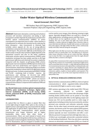
(b) Eye diagram @ 50 km distance
It can be seen from the result that as the distance increases
the output in terms of Q-factor and eye diagram decreases.
4. Conclusion
As power consumption is an importantissuein under-water
missions, it is fundamental to minimize the intensity loss by
reducing the beam divergence , data transmission in
relatively high turbidity waters appeals for the use of
energy-efficient modulations and powerful channel codes at
the physical and data link layers. In this paper underwater
wireless optical link is generated using optisystemsoftware.
The link is simulated for 10 km to 50 km and the distortions
are taken into consideration. It can be seen from the result
that as the distance increases theoutputgetsmoredistorted.
The output is better at 10 km compared to 50 km in terms of
Q-factor, Bit Error Rate and eye Diagram.
5. References
[1] Chadi Gabriel, Mohammad-Ali Khalighi, Salah
Bourennane, Pierre Le´on, Vincent Rigaud – “Investigation
of Suitable Modulation Techniques for UnderwaterWireless
Optical Communication” Published by-IEEE.ISSDN No.:978-
1-4673-2733-6 ,2012.
[2] Mohammad-Ali Khalighi1, ChadiGabriel,TasnimHamza,
Salah Bourennane. Pierre Le´on, Vincent Rigaud.
―”Underwater WirelessbOptical Communication; Recent
Advances and Remaining Challenges”,
Published by-IEEE. ISSDN No.: 978-1-4799-5601-2 , 2014.
[3] Hai-Han Lu1, Chung-Yi Li1, Hung-Hsien Lin1, Wen-Shing
Tsai2, Chien-An Chu1, Bo-Rui Chen1, and Chang-Jen Wu1, ―
“An 8 m/9.6 Gbps underwater wireless optical
communication
System” , Published by- IEEE,2016.
[4] Yuhan Dong, Jinxing Liu ― “On BER Performance of
Underwater Wireless Optical MISO Links under Weak
Turbulence” published by- IEEE ISSDN No. : 978-1-4673-
9724-7,2016.
[5] Xuelong Mi and Yuhan Dong ― “Polarized Digital Pulse
Interval Modulation for Underwater Wireless Optical
Communications”, published by-IEEE,ISSDN No.: 978-1-
4673-9724-7 ,2016.
[6] Xifeng Li, Xinsheng You,,Meihong Sui, ―Evaluation of
Underwater Wireless Optical Communication Link with
Pspice Simulator 1-4244-1312-5/07,2007.
[7] Podila Swathi , Shanthi Prince ,-“ Designing Issues in
Design of Under Water Optical Wireless Communication”
Published by IEEE, ISSDN No. : 978-1-4799-3357-7 (1440-
1445), 2014.](https://image.slidesharecdn.com/irjet-v4i237-171113092351/85/Under-Water-Optical-Wireless-Communication-3-320.jpg)

This document discusses underwater wireless optical communication (UWOC). It begins by introducing some key challenges of UWOC, such as attenuation and fading caused by absorption, scattering, and turbulence in water. It then discusses different modulation techniques that have been used for UWOC, including on-off keying (OOK), digital pulse interval modulation (DPIM), and polarization shift keying (Polk). The document proposes a new modulation scheme called polarized DPIM (P-DPIM) that combines PPM and Polk to improve power efficiency and error performance over long distances. It presents the results of a simulation comparing P-DPIM to other modulation schemes at different transmission distances, finding that P-DPIM provides better performance