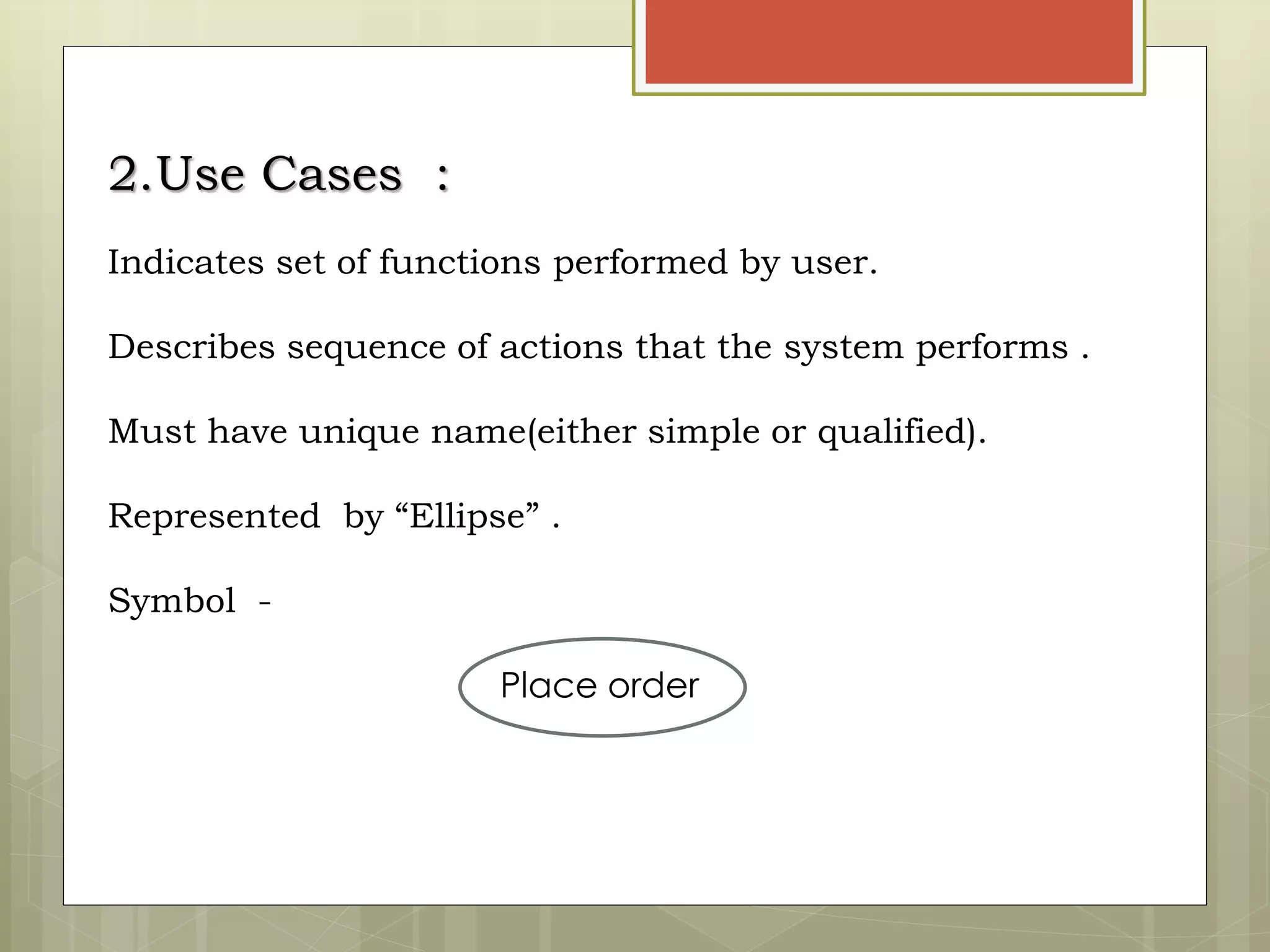
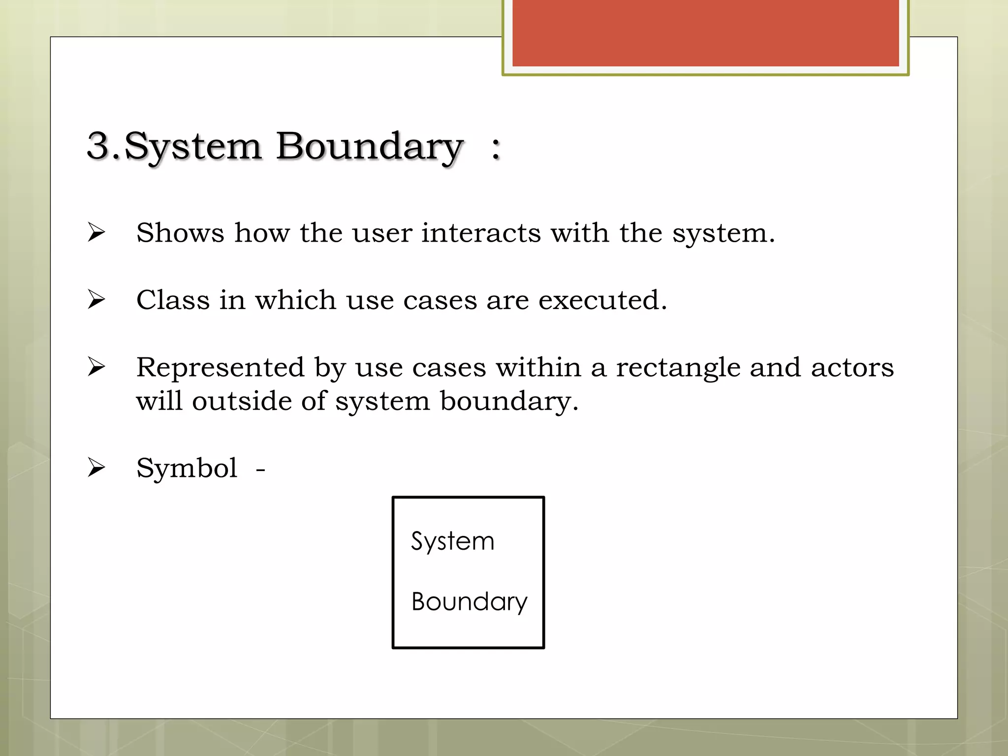
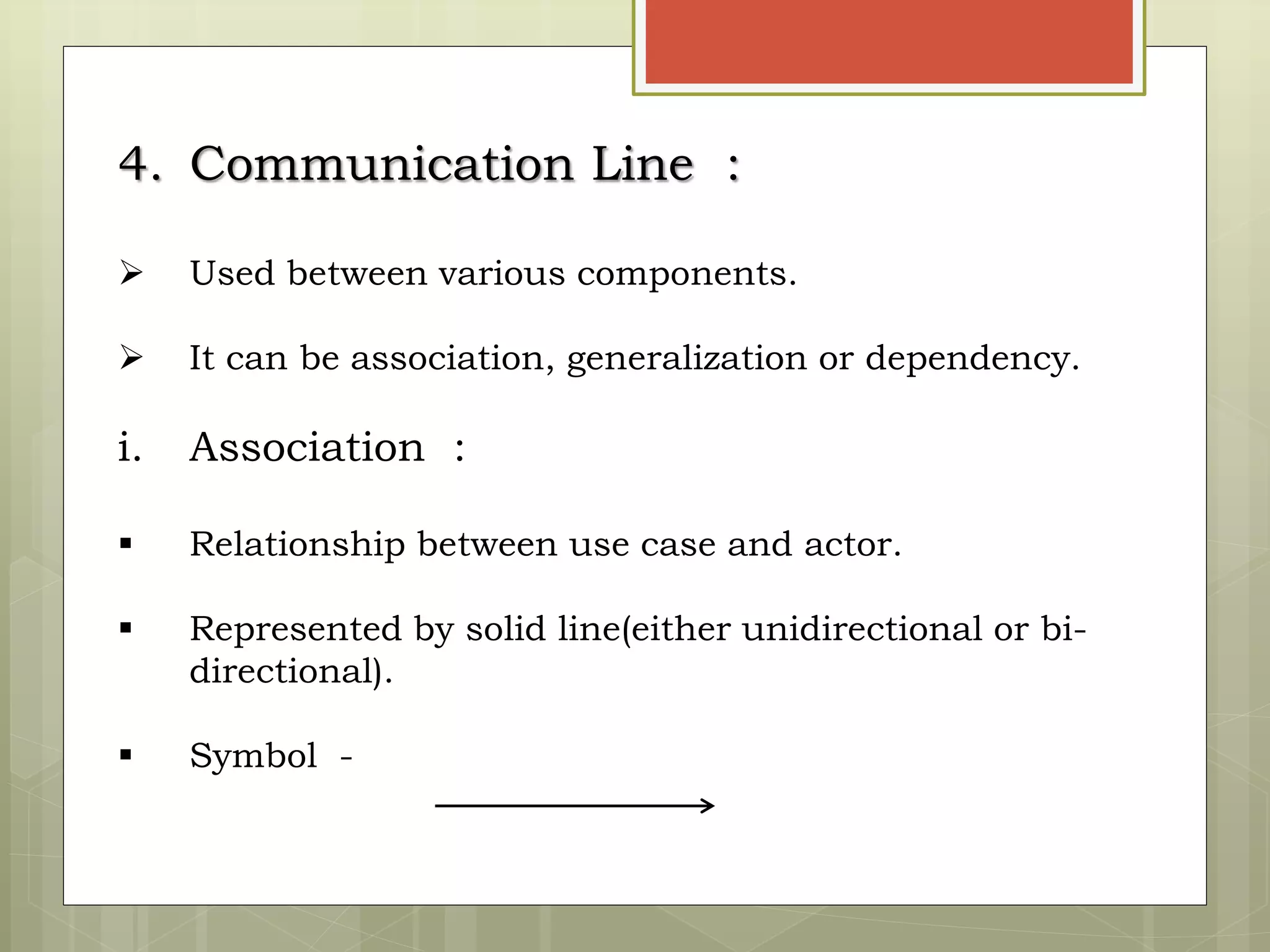
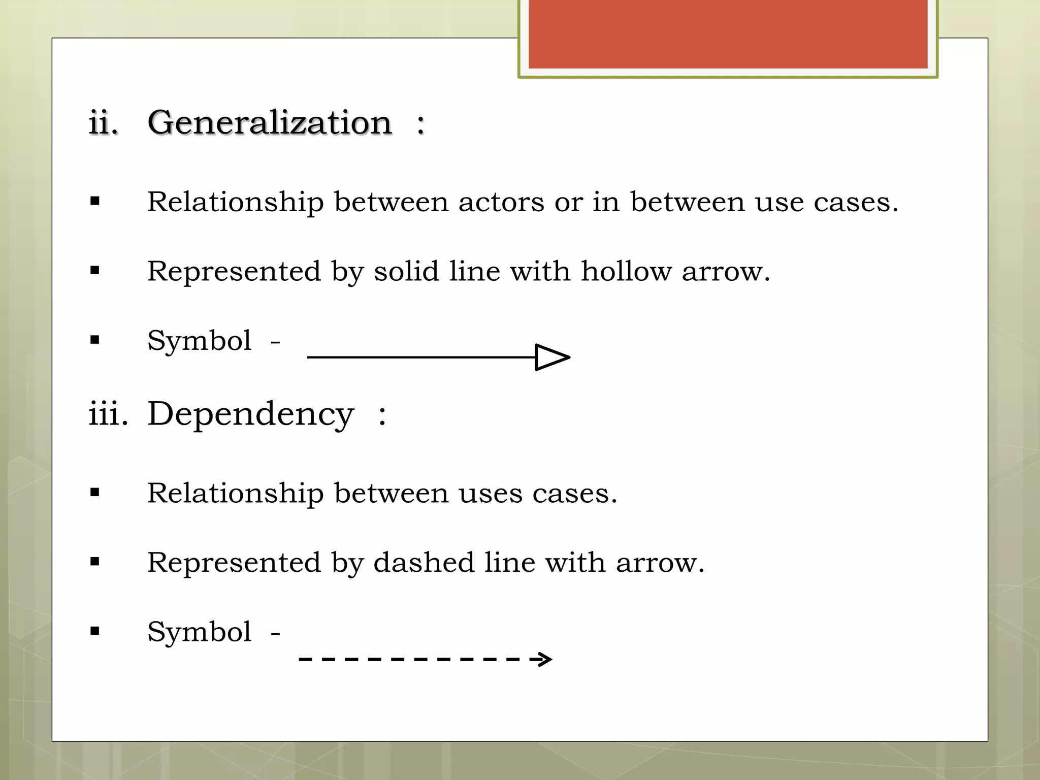
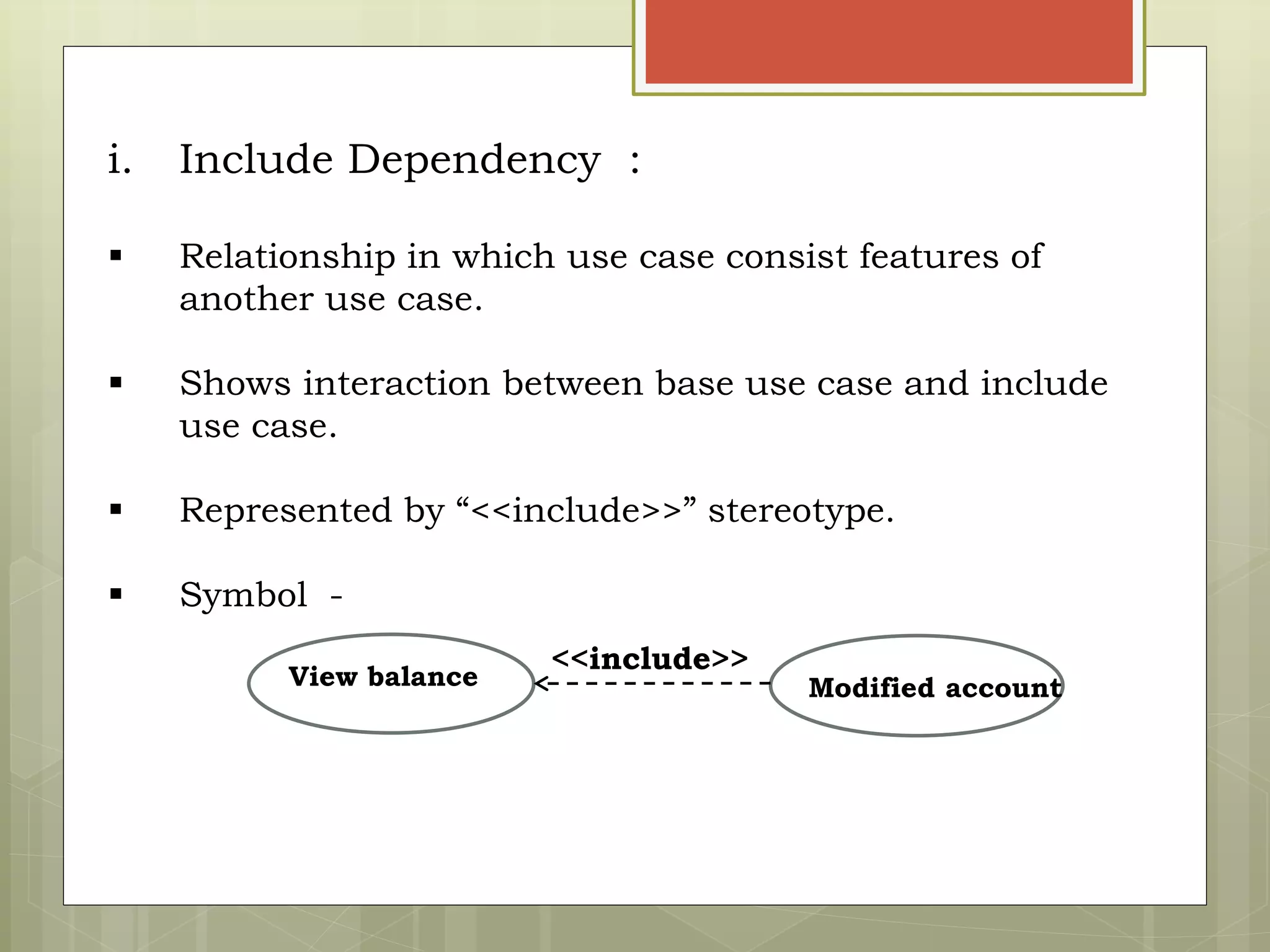
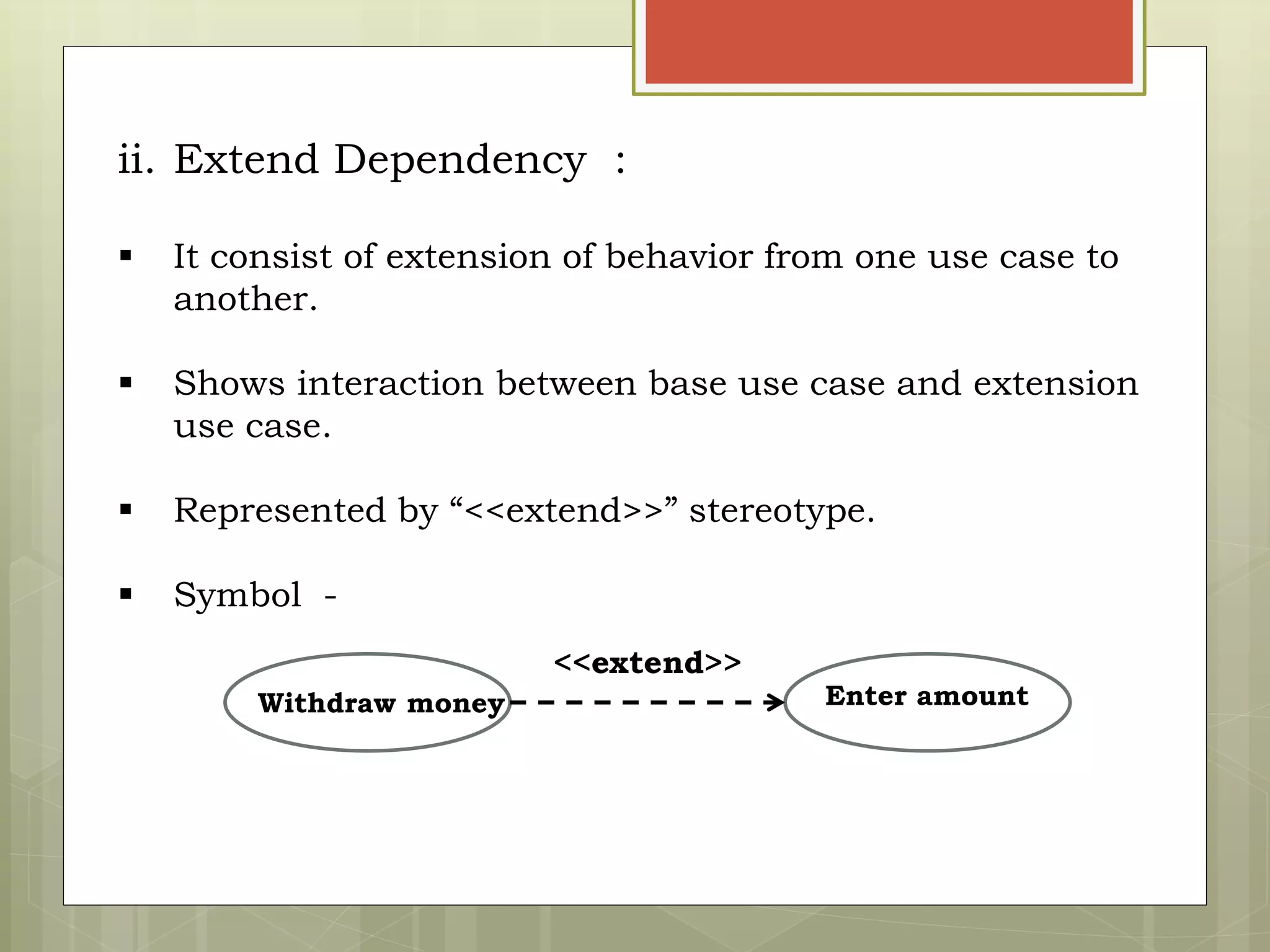
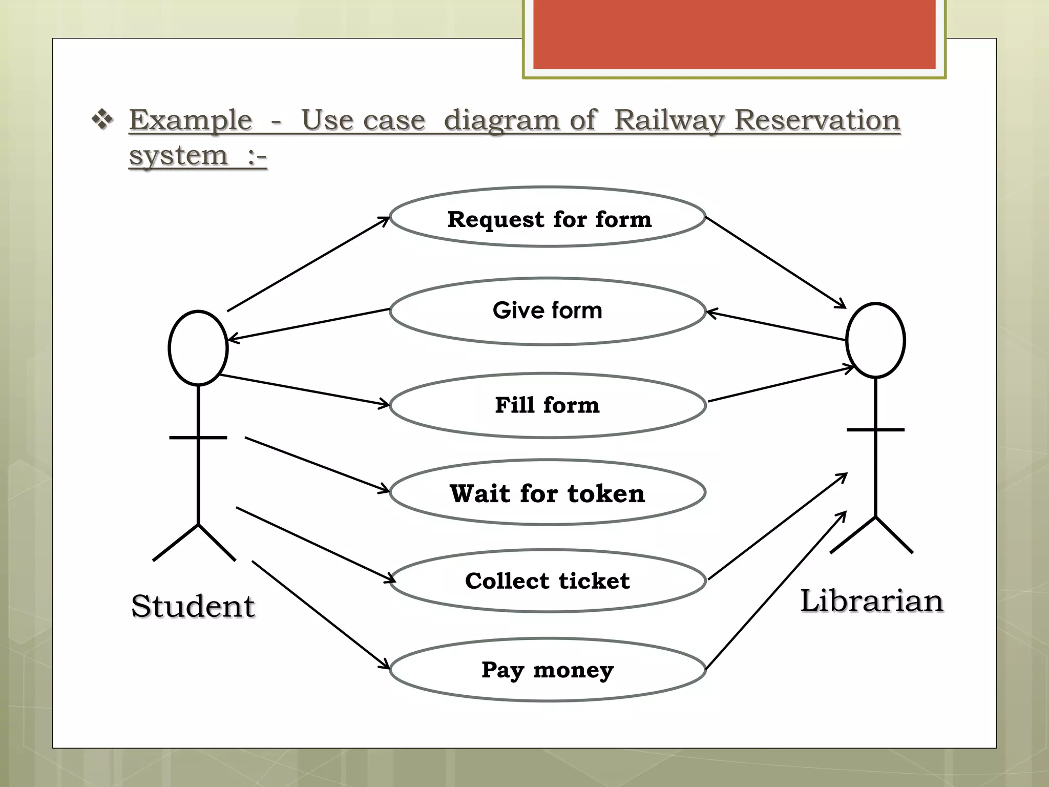
UML
Diagrams :
Use Case Diagram
INTRODUCTION :
 Use Case Diagram is invented by Jacobson.
 Specifies the static use case view and functionality of a
system.
 Useful in modeling the behavior of system.
 Used to gather requirements and to get outside view of a
system.
 Identifies external and internal factors influencing a
system.
 Shows interaction among actors.
Terms and concepts :
1. Actor :
 performs functions of a system
 Represents role played by a person that interacts
with a system.
 Responsible for giving input to system .
 Uses processed output for performing particular
action.
i. Primary Actor :
 People who performs main system functions.
ii. Secondary Actor :
 People who performs admin/ maintenance task.
iii. External Hardware :
 Hardware devices which are part of application.
iv. Other Systems :
 Other systems with which the system must interact.
2.Use Cases :
Indicates set of functions performed by user.
Describes sequence of actions that the system performs .
Must have unique name(either simple or qualified).
Represented by “Ellipse” .
Symbol -
Place order
3.System Boundary :
 Shows how the user interacts with the system.
 Class in which use cases are executed.
 Represented by use cases within a rectangle and actors
will outside of system boundary.
 Symbol -
System
Boundary
4. Communication Line :
 Used between various components.
 It can be association, generalization or dependency.
i. Association :
 Relationship between use case and actor.
 Represented by solid line(either unidirectional or bi-
directional).
 Symbol -
ii. Generalization :
 Relationship between actors or in between use cases.
 Represented by solid line with hollow arrow.
 Symbol -
iii. Dependency :
 Relationship between uses cases.
 Represented by dashed line with arrow.
 Symbol -
i. Include Dependency :
 Relationship in which use case consist features of
another use case.
 Shows interaction between base use case and include
use case.
 Represented by “<<include>>” stereotype.
 Symbol -
View balance Modified account
<<include>>
ii. Extend Dependency :
 It consist of extension of behavior from one use case to
another.
 Shows interaction between base use case and extension
use case.
 Represented by “<<extend>>” stereotype.
 Symbol -
Withdraw money Enter amount
<<extend>>
 Example - Use case diagram of Railway Reservation
system :-
Student Librarian
Pay money
Request for form
Fill form
Collect ticket
Wait for token
Give form
UML  Diagrams
UML  Diagrams

UML Diagrams

  • 1.
  • 2.
    INTRODUCTION :  UseCase Diagram is invented by Jacobson.  Specifies the static use case view and functionality of a system.  Useful in modeling the behavior of system.  Used to gather requirements and to get outside view of a system.  Identifies external and internal factors influencing a system.  Shows interaction among actors.
  • 3.
    Terms and concepts: 1. Actor :  performs functions of a system  Represents role played by a person that interacts with a system.  Responsible for giving input to system .  Uses processed output for performing particular action.
  • 4.
    i. Primary Actor:  People who performs main system functions. ii. Secondary Actor :  People who performs admin/ maintenance task. iii. External Hardware :  Hardware devices which are part of application. iv. Other Systems :  Other systems with which the system must interact.
  • 5.
    2.Use Cases : Indicatesset of functions performed by user. Describes sequence of actions that the system performs . Must have unique name(either simple or qualified). Represented by “Ellipse” . Symbol - Place order
  • 6.
    3.System Boundary : Shows how the user interacts with the system.  Class in which use cases are executed.  Represented by use cases within a rectangle and actors will outside of system boundary.  Symbol - System Boundary
  • 7.
    4. Communication Line:  Used between various components.  It can be association, generalization or dependency. i. Association :  Relationship between use case and actor.  Represented by solid line(either unidirectional or bi- directional).  Symbol -
  • 8.
    ii. Generalization : Relationship between actors or in between use cases.  Represented by solid line with hollow arrow.  Symbol - iii. Dependency :  Relationship between uses cases.  Represented by dashed line with arrow.  Symbol -
  • 9.
    i. Include Dependency:  Relationship in which use case consist features of another use case.  Shows interaction between base use case and include use case.  Represented by “<<include>>” stereotype.  Symbol - View balance Modified account <<include>>
  • 10.
    ii. Extend Dependency:  It consist of extension of behavior from one use case to another.  Shows interaction between base use case and extension use case.  Represented by “<<extend>>” stereotype.  Symbol - Withdraw money Enter amount <<extend>>
  • 11.
     Example -Use case diagram of Railway Reservation system :- Student Librarian Pay money Request for form Fill form Collect ticket Wait for token Give form