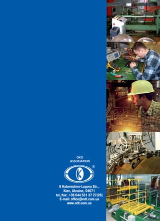
www.ndt.com.ua
Ukraine, 04071 Kiev, 8 Naberezhno Lugova Str.
tel./fax: +38 044 531 37 27 (26)
PROMPRYLAD LLC ULTRACON SERVICE LLC UkrSRINDT
TM
®
®
NON DESTRUCTIVE
T E S T I N G
OKO
ASSOCIATION
DEAR SIRS!
OKO Association motto: "Turnkey NDT technologies".
We are trying to solve all the problems, connected with non-
destructive testing (NDT). Included to "OKO" Association enterprises
have a full range of means for designing, manufacturing, warranty
and post-warranty services of different equipment and NDT means,
development of techniques and technologies of NDT procedure,
training and certification of NDT personnel.
For objects detection we have covered practically all the sphere of
NDT methods: ultrasonic, eddy current, visual, penetrant, magnetic
particle and acoustic emission. Moreover by the Customer`s request
we also provide technical check-up, technical diagnostics (expert evalua-
tion), thickness gauging of base metal and welded joints of equipment.
We can help you, if you decided to carry out non-destructive
testing in your own laboratory.
NDT technologies division of Ukrainian Scientific Research Institute
for Non-Destructive Testing (UkrSRINDT) is the developer of more
than 50 NDT techniques for different items. Up-to-date NDT tech-
nologies are used when designing new techniques. The department is
equipped with all the necessary equipment for implementation of
different testing methods such as ultrasonic, eddy current, acoustic
emission, magnetic particle, visual and penetrant. One method or a
group of methods is separately chosen for optimum solution to problem.
Integrated approach is used for each specific testing task.
We use high-level equipment for NDT techniques implementation.
"OKO" Association includes the leaders of domestic engineering in the
field of non-destructive testing such as Ultracon-Service LLC and
Promprylad LLC. Ultrasonic, eddy current and magnetic particle flaw
detectors, hardness testers, thickness gauges, wide range of ultrasonic
and eddy current probes and other equipment have worked up
Ukrainian market long ago due to its high quality and moderate prices.
Also, UkrSRINDT successfully designs high-efficiently Systems of
automated NDT at customer's request. It is both important and useful
to show to the customer that if the solution of an assigned testing task
was not found with serial equipment, than it is possible to design special-
purpose probes and make additions to the instrument software.
Manufacturing companies to all delivered equipment hold consulta-
НДІ
tions on its implementation at a customer`s enterprise and carry out
starting-up and commissioning of NDT systems.
But unfortunately, it's impossible to produce everything. If it's dif-
ficult to solve the testing task using instruments, produced by our
companies, "OKO" Association can supply the necessary equipment,
made by other producers.
Among such equipment are X-ray units, consumables for magnetic
particle and penetrant testing.
Service center of Promprylad LLC provides warranty and post-warranty
services for all supplied equipment.
It is well known, that without skillful specialists any, even perfect-
made equipment, is just "piece of iron". NDT Training Center of
Ultracon-Service LLC, NDT Certification Center of Promprylad LLC and
Personnel Certification Center of UkrSRINDT (Accreditation certificate
of National Accreditation Agency of Ukraine NAAU No.6O012 dated
14.01.2014) will train NDT specialists of your enterprise and then issue
them a certificate in conformity with the acting Regulatory
Documentation. We are deeply convinced that only the authors of NDT
procedures and designers of NDT instruments can provide proper training
for carrying out the testing. We got all research engineers, methodolo-
gists, designers, producers of instruments, lecturers and experts together
"under one roof". As a result optimal solution of any testing task can be
found for the customer!
OKO Association - technology must be “Turnkey”. It is the main
principle of our work.
PROMPRYLAD LLC
ULTRACON SERVICE LLC
Ukrainian
scientific research institute
for non destructive testing
OKO ASSOCIATION TM
TABLE OF CONTENTS
НДІ
2
UKRAINIAN
SCIENTIFIC
RESEARCH INSTITUTE
FOR NON DESTRUCTIVE
TESTING
Ultrasonic testing:
• SONOCON B ultrasonic flaw detector and thickness gauge _ _ _ _ _ _ _4
• UD4 76 ultrasonic flaw detector _ _ _ _ _ _ _ _ _ _ _ _ _ _ _ _5
• UD3 71 ultrasonic flaw detector small sized _ _ _ _ _ _ _ _ _ _ _6
• TOFD PRO System _ _ _ _ _ _ _ _ _ _ _ _ _ _ _ _ _ _ _ _ _ _ _ _ _ _7
• OKO 22M EMA ultrasonic multi-channel flaw detector _ _ _ _ _ _ _ _8
• OKO 22M UT ultrasonic multi-channel flaw detector _ _ _ _ _ _ _ _ _9
• Ultrasonic probes for flaw detection and sizing _ _ _ _ _ _ _ _ _10 15
• TOFD transducers _ _ _ _ _ _ _ _ _ _ _ _ _ _ _ _ _ _ _ _ _ _ _ _ _16
• UTG-8 ultrasonic thickness gauge _ _ _ _ _ _ _ _ _ _ _ _ _ _ _ _ _ _17
Eddy current testing:
• VD3 81 EDDYCON eddy current flaw detector _ _ _ _ _ _ _ _ _ _ _ _19
• EDDYCON С eddy current flaw detector _ _ _ _ _ _ _ _ _ _ _ _ _ _ _20
• EDDYCON D eddy current multi-channel flaw detector _ _ _ _ _ _ _ _21
• Ultrasonic and eddy current calibration blocks _ _ _ _ _ _ _ _ _ _ _ _22
• Eddy current production probes. Standart compliant EN13860 2 _ _ _ _ _23
Mechanized and automated non destructive testing systems:
• UDS2 73 MR ultrasonic double rail flaw detector _ _ _ _ _ _ _ _ _25 26
• UDS2 77 ultrasonic single rail flaw detector _ _ _ _ _ _ _ _ _ _ _ _ _27
• UD3 71 flaw detector for ultrasonic testing of rail welds _ _ _ _ _ _ _28
• Series of magnetic particle testing systems for railway wheels
UMPK 3 and UMPK 5 _ _ _ _ _ _ _ _ _ _ _ _ _ _ _ _ _ _ _ _ _ _ _29
• UMPK-8 system for wet magnetic particle testing of couplings _ _ _ _30
• UMPK-38 System for magnetic particle testing
and flaw detection of railway axles _ _ _ _ _ _ _ _ _ _ _ _ _ _ _ _ _31
• OS 3
System for ultrasonic and eddy current in line testing of railway axles _32
• OS 4 System for ultrasonic immersion testing of railway axles _ _ _ _ _33
• SAUZK T-18US system for automated ultrasonic testing of pipes _ _ _ _34
• T 18, T 18VT
System of automated non destructive testing of pipe`s body _ _ _ _ _35
• SNK “YUG” system for automated ultrasonic in-line testing
of wheels and tyres _ _ _ _ _ _ _ _ _ _ _ _ _ _ _ _ _ _ _ _ _ _ _ _36
• KP 8 Automated system
for complex non destructive testing of railcar wheelsets _ _ _ _ _ _ _ _37
• PSH 11
System of automated ultrasonic testing of longitudinal welded pipes _ _38
Personnel certification body
• PCB “UkrSRINDT” _ _ _ _ _ _ _ _ _ _ _ _ _ _ _ _ _ _ _ _ _ _ _39-40
ULTRACON SERVICE LLC
TM
PROMPRYLAD LLC
8, Naberezhno Lugova Str., Kiev,
Ukraine 04071
Tel./ Fax: +38 044 467 51 38(39)
E mail: office@ndt.com.ua
www.promprilad.ua
TM
4
U L T R A S O N I C
FLAW DETECTOR
& THICKNESS GAUGE
SONOCON BSONOCON B
PURPOSE
SONOCON B ADVANTAGES
ERGONOMICS
• Optimal dimensions and display format of 800x480
pixel resolution ensures qualitative data separation
and its perception and does not cause excessive eye-
strain to NDT inspector.
• Convenient case and small device weight allow to use
the flaw detector in enclosed spaces and hard to
reach areas.
• All main instruments setting are accessible with key-
pad shortcuts.
• Call of the most frequently used modes from the key-
pad or “Quick Access Menu”.
MULTIFUNCTIONALITY
• Carrying out the flaw detection, thickness gauging,
sound velocity assessment in different materials.
• Availability of various flaw detector software versions
(“firmware upgrade”) for solution of special purpose
testing tasks.
• Results analysis and reports generation PC software.
• Operation with all probe types.
INDIVIDUAL DELIVERY SET
• By agreement with the Customer the flaw detector
can be completed with different probes, calibration
blocks and software for operation in different industri-
al sectors.
UT Basic software version:
• Manual non destructive testing for the presence of defects such as discon-
tinuity and inhomogenuity of the material of finished items, semi finished
products and welded (soldered) joints.
• Measuring the defects depth and coordinates.
• Assessing the sound velocity in different materials.
• Measuring the equivalent defect sizes.
• Measuring the ratio of signal amplitudes, reflected from defects.
“Thickness gauge +” software version:
MAIN MODES AND OPTIONS
• Pulser modes: spike pulser, square wave pulser.
• Automatic algorithms of various probes calibration
(straight beam, angle beam, rayleigh wave).
• Mode of automatic building of DGS diagrams simul-
taneously for three different acceptance diameters.
• DAC modes: building DAC curve according to
EN1712, EN1713, EN1714, ASTM E164, ASME,
ASME III, JIS 23060, GB11345.
• TCG: dynamic range of 110 dB.
• Mode of Automatic Gain Control (AGC).
• Acoustic coupling control.
• Measurement of echo signal parameters by the “Scan”
of a peak signal (useful while products testing with bad
input conditions of ultrasonic vibrations).
• Mode of high accuracy thickness measurement of a
product with the application of a measurement marker.
• “Legs marking” mode (applied during welded joints
testing).
• “Peak hold” mode peak value of the signal envelope
accumulation, this mode is useful during small defects
search and operation in unstable acoustic coupling
conditions.
• Availability of two independent measurement gates
with three levels, as well as the system of automatic
flaw alarm (light and sound) by each measurement
gate.
• Different rectification modes radio frequency (RF),
positive or negative halfwave, full wave.
• Fast data transmission to PC via USB Flash.
• Result display: A Scan, B Scan. C Scan (“Thickness
gauge+” version).
• Testing report in a form of *.jpg
• Temperature range: from minus 25 to plus 50 0
C.
APPLICATION
• Weld testing in the Power Generation and
Petrochemical Industries.
• Precise measurement of thickness in the Automo-
tive Industry.
• Corrosion measurement in the Power Generation
and Petrochemical Industries.
• Forgings testing.
• Testing of special purpose materials in the Aero-
space and Automotive Industries.
• Measuring the products thickness at one sided
access to them.
• Formation of multi dimensional files with the thick-
ness measurement results of the testing objects.
5
UD4 76 FLAW DETECTOR ADVANTAGES
• Operation with any type of piezoelectric trans-
ducers.
• Thickness measurement.
• A scan, B scan, orthographic views of 3D scan.
• Synchronization: internal, external from
encoder.
• Scanning speed control.
• Rectification: full wave, positive and negative
halfwaves and radio frequency (RF) signals.
• Set of gain control functions, including AGC,
TCG.
• Interface of automatic calibration of a probe
and test piece.
• Mode for operation with DGS diagrams.
• Two independent three level measuring gates.
• Two additional special purpose probes.
• DAC curves, automatic plotting of TCG curves
by DAC curves.
• Coupling control system.
• ALARM system at all gate levels.
• Bright three color alarm LED`s.
• Mode of current signal overlaying on earlier
frozen one (“freeze and live” mode).
• Signals spectrum display.
• Dynamic control of the pulser parameters
depending on the probe frequency.
• Reflections highlight mode.
• Special program interface.
• “User” and “Expert” menu modes.
• Voice comments recording referred to all data
types.
• Large, high contrast TFT display.
• Storage and call of testing results.
• Communication with PC via USB.
ULTRASONIC
FLAW DETECTOR
UD4 76UD4 76
PURPOSE
Intended for manual and mechanized testing of products to detect defects
such as discontinuities and inhomogenuity of materials, items and
semi finished products, welded joints, measurement of signal amplitudes
ratio from flaws, flaws coordinates. Tomography function allows reflecting
and saving testing results in a form of B scan with the affixment to the scan-
ning path.
ADDITIONAL FUNCTIONS
• SAFT mode
SAFT algorithm, implemented in the results pro-
cessing software, allows significantly improve the
signal/noise ratio, virtually change the probe angle,
with which the testing was carried out.
• Building the “corrosion map” “thickness map”
This software function allows to build the thickness
map of a tested object by the results of a raster
scanning.
This simplifies the visual perception of testing
results and their convenient registration.
• Radio frequency signal.
For the high accuracy measurement of item thick-
ness and flaw coordinates the RF signal is used,
providing the measurement step of 0.01 mm.
• Special program interface mode.
This mode is applied to solve special purpose tasks
while testing different one type parts or in a case
when the part has many testing areas.
EN 12668 1 Compliant
Б6
UD3 71 FLAW DETECTOR ADVANTAGES
• MULTIFUNCTIONALITY — carrying out of flaw
detection, thickness gauging, and assessment of
sound velocity in the material.
• MINIMAL DIMENSIONS OF FLAW DETECTOR no
more than (188 x 107 x 78) mm, assure high ergo-
nomics of the instrument and simplicity of operation.
• ERGONOMICS — convenient case, small weight,
high contrast TFT display, assignment of the most
frequently used functions to keypad "hot keys", and
usage of a special leather cover for handy and
secure holding of the instrument in a hand.
• INDIVIDUAL DELIVERY SET
By agreement with the Customer the instrument
can be completed with different special purpose
probes, calibration blocks and software for operation
in different industrial sectors.
SEALING PROTECTION AND OPERATING CONDITIONS
• Sealing protection IP65.
• Ambient temperature minus 30 to plus 45°C.
• Measuring the flaws coordinates.
• Measuring the different items thickness at one sided access to them.
• Measuring the echo amplitudes ratio.
• Measuring the equivalent sizes of flaws.
• Evaluating the sound velocity in different materials.
ULTRASONIC
FLAW DETECTOR
UD3 71UD3 71
SMALL SIZED
PURPOSE
UD3 71 ultrasonic flaw detector provides the testing of welded
joints and base materials along with thickness measurement of
monometals, bimetals in compliance with Regulatory Documenta-
tion in various industrial sectors.
MAIN MODES AND OPTIONS
• “TCG” and "DAC" modes for plotting the time
corrected gain curve and DAC curve.
• “AGC” mode of automatic gain control.
• Mode for operation with DGS diagrams.
• "Legs marking" mode (indispensable during
welded joins testing).
• “Peak” mode (indispensible during small
defects search, operation in unstable acoustic
coupling conditions).
• Rectification: full wave, positive and negative
halfwaves and radio frequency (RF) signals.
• Availability of two independent measurement
gates, each having automatic three level flaw
alarm system (ALARM).
• Possibility to create special purpose inter-
faces to solve certain tasks when performing
ultrasonic testing.
• Accurate measurement of product thickness
(with manual choice of position of a measu-
ring pointer.
• Measurement of operating frequency of
applied probe.
• Selection of information display modes:
A scan, B scan.
• Fast data transfer to PC and their analysis in
“Ultra UDx 7x” program application with the
possibility of testing report storing and prin-
ting.
7
THE BEST
SOLUTION FOR HIGH-QUALITY
ULTRASONIC TESTING OF WELDS.
TOFD PROTOFD PRO SYSTEM
• Profile types: CRC Evans, single J groove weld,
single V groove weld, double V groove weld,
X welds, etc.
• Conventional wall thickness: from 6 mm (0.25 inch).
• Tube material: standard carbon steels.
• Testing with up to 4 pairs of TOFD probes according
to standards CEN/TS 14751:2004, ENV 583 6:2000
Non destructive testing.
Time of Flight diffraction technique as a method
for defect detection and sizing.
• Detection of defects of various orientation (longi-
tudinal, transverse), precise determination of a
depth and length of defects, high sensitivity from
its corner position.
• Testing scheme fully covers the groove area and
the whole volume of a welded joint.
• Testing the whole volume of the welded joint per
one scanning cycle.
THE SYSTEM SOFTWARE INCLUDES
THE FOLLOWING PAGES (MODULES):
The “Object” page ensures:
• Selecting the test object geometry and setting
up its geometrical dimensions.
• Selecting the type of test object material.
• Selecting the type of weld bevel and setting up
of all geometrical dimensions.
The “Scanner” page ensures:
• Selecting the scanner.
• Setting up the scanner type: manual, motor operated.
• Setting up the spatial position of TOFD transducers
pair relative to the origin of the coordinate system.
• Using of up to 4 TOFD transducer pairs.
• Carrying out the encoder calibration.
The “TOFD setup” page ensures:
• Selecting the type of TOFD probes,
TOFD wedges, setup of their parameters.
• Setting up the PCS the distance between the
index points of TOFD transducers and their shift
relative to the welded joint axis.
• Calculation and graphic plotting of the following
parameters when using the TOFD Calculator:
• Spatial resolution (R);
• Scanning surface dead zone (Dds);
• Backwall dead zone (Ddw);
• Locus curve;
• Beam Spread.
CEN/TS 14751:2004 Compliant
EN 5836:2000 Compliant
PURPOSE
TOFD PRO System is intended for mechanized testing of welded joints
using Time of Flight Diffraction (TOFD) technique. The System assures
the solution of the following tasks testing the welded joints of:
Figure 4. Data analysis.
Figure 1. Object.
Figure 2. Scanner.
Figure 3. TOFD setup.
CONFIGURATIONS
OF TESTED WELDED JOINTS:
• flat objects;
• tubes of medium and large diameters (with min. outer diameter of 600 mm);
• spherical and cylindrical oil and gas tanks (with min. diameter of 10 m).
1
2
3
4
8
THE BEST INDUSTRIAL SOLUTION FOR
IN-LINE AND IN-SERVICE SYSTEMS.
EMA ULTRASONIC
MULTI-CHANNEL
FLAW DETECTORS
ОКО 22M EMA V.2,ОКО 22M EMA V.2,
ОКО 22M EMA PROОКО 22M EMA PRO
PURPOSE
The ОКО 22М EMA ultrasonic multi-channel flaw detector is an inde-
pendent electronic device and is designed for application in in line and
off line high performance systems (automated multi channel NDT
Systems), transportable systems (mechanized NDT systems) or for man-
ual testing.
Due to the flaw detector is designed in a form of a standalone device
with the connection to the PC via Ethernet port, several EMA channels
can be connected to the PC via Switch unit. This allows to create EMA
multi channel testing systems.
THE ОКО 22М EМА MAIN SPECIFICATIONS
TCG
• Depth _ _ _ _ _ _ _ _ _ _ _ _ _ _ _ _ _ _ _ _ _ _ _ _ _ _ _ _ _ _ _ _entire gain range;
• Number of points _ _ _ _ _ _ _ _ _ _ _ _ _ _ _ _ _ _ _ _ _ _ _ _ _ _ _ _ _ _up to 20;
• Minimum time step between TCG points _ _ _ _ _ _ _ _ _ _ _ _ _ _ _ _ _ _ 1 us;
• Maximum slope _ _ _ _ _ _ _ _ _ _ _ _ _ _ _ _ _ _ _ _ _ _ _ _ _ _ _ _ _ _ 46 dB/us;
DATA PORTS
• Ethernet (for communication with PC).
CONNECTORS
• 2 pairs of lemo00 connectors for connecting the EMAT to the receiver of EMA channel;
• 2 BNC connectors (one connector for the first pulser, second connector for
the second pulser);
• 1 lemo connector for Encoder connection;
• 1 Power connector;
• 1 Ethernet connector for transmitting the data to PC;
• 1 Trigger connector is used either for synchronization between EMA chan-
nels, or for EMA channel metrological verification.
Catalog Frequency, Probe Working surface Connector Connector
number MHz angle, 0
size, mm type position
EMAT0.5 0 0.5 0 20 x 20 2Lemo00/BNC cable
EMAT0.5 90 0.5 90 20 x 20 2Lemo00/BNC cable
EMAT1 0 1.0 0 20 x 20 2Lemo00/BNC cable
EMAT1 45 1.0 45 20 x 20 2Lemo00/BNC cable
EMAT1 90 1.0 90 20 x 20 2Lemo00/BNC cable
EMAT2 0 2.0 0 20 x 20 2Lemo00/BNC cable
EMAT2 45 2.0 45 20 x 20 2Lemo00/BNC cable
EMAT2 90 2.0 90 20 x 20 2Lemo00/BNC cable
EMAT4 0 4.0 0 20 x 20 2Lemo00/BNC cable
EMAT4 45 4.0 45 20 x 20 2Lemo00/BNC cable
EMAT4 90 4.0 90 20 x 20 2Lemo00/BNC cable
EMAT5 0 5.0 0 20 x 20 2Lemo00/BNC cable
EMAT5 45 5.0 45 20 x 20 2Lemo00/BNC cable
EMAT6 0 6.0 0 20 x 20 2Lemo00/BNC cable
EMAT8 0 8.0 0 20 x 20 2Lemo00/BNC cable
* Working surface size and dimensions of EMA probes can be performed at the customer`s request.
Available high temperature EMAT modification.
TRANSDUCERS SPECIFICATIONS
EMA Transducers
A/D CONVERTER
•10 bit, 80 MHz.
PULSER
• Initial pulse filling frequency (Selection of a frequency filling is
determined by the testing task. Available 2 channels
with different frequencies); _ _ _ _ _ _ _ _ 0.5, 1, 2, 4, 8 MHz;
(Up to 8 MHz available as an extra option);
• Type of initial pulse _ _ _ _ _ _ _ _ _ _ _ _ _Toneburst, Waveform
• Number of periods _ _ _ _ _ _ _ _ _ _ _ _ _ _ _ _ _ _ _ _ _ _ _2 6;
• Pulser amplitude _ _ _ _ _ _ _ _ _ _ _ _ _ _ _ _ _ _up to 2000 Vpp;
• Pulse energy _ _ _ _ _ _ _ _ _ _ _depends on a filling frequency;
• Pulse repetition frequency (PRF) _ _ _ _ _ _from 50 to 1000 Hz
(OKO-22M-EMA PRO 2000 Hz);
RECEIVER
• Gain adjustment _ _ _ _ _ _ _ _ _ _ _ _ _ _ _ _ _ _28 dB to 68 dB
_ _ _ _ _ _ _ _ _ _ _ _ _ _ _ _ _ _ _ _(gain step 0.1, 0.5, 1, 2 dB).
• Filter _ _ _ _ _ _ _ _ _ _ _ _ _ _ _ _ _ _ _ _0.5, 1, 2, 3, 4, 5, 6 MHz
(Selection of a frequency filling is determined by the testing task.
Available 2 channels with different narrow band filter);
• Delay _ _from 0 to 1000 mm in steel (sound velocity 3230 m/s);
• Range _ _from 1 tо 6000 mm in steel (sound velocity 3230 m/s);
• Number of averages _ _ _ _ _ _ _ _ _ _ _ _ _ _2 / 4 / 8 / 16 / 32;
• Data presentation _ _ _ _ _ _ _ _ _ _ _А Scan; B Scan; C Scan;
GATES
• Two independent gates per channel Amplitude and time
measurements;
• Two levels per gate.
PURPOSE
The ОКО 22М UT ultrasonic multi-channel flaw detector is a standalone elec-
tronic unit and is intended for application in high performance automated
multi channel NDT Systems, transportable systems (mechanized NDT systems) or for
manual testing.
Available in several flaw detector models that are different in a volume of built in
functions for results processing.
Due to the flaw detector is designed in a form of a
standalone device with the connection to the PC via
Ethernet port, the several UT channels can be connected
to the PC via Switch unit. This allows to create UT
multi channel testing systems.
Technical capabilities of the flaw detector allow to use
it both in stationary type and rotary testing systems.
THE BEST INDUSTRIAL OEM SOLUTION FOR
IN-LINE AND IN-SERVICE NDT SYSTEMS.
ULTRASONIC
MULTI-CHANNEL
FLAW DETECTORS
OKO-22M-UTOKO-22M-UT Standart,
OKO-22M-UTOKO-22M-UT StandartMX,
OKO-22M-OKO-22M-UT PROUT PRO
SPECIFICATIONS
• Pulser mode Spike pulser, Square Wave pulser
(OKO-22M-UT PRO)
• Pulse Voltage (SQ mode) 120 300 V in steps 10 V with tolerance 10%
• Pulse falling/rising time 5 ns
• Pulse Width (SQ mode) 20 500 ns in steps 10 ns with tolerance 10%
• PRF (SQ mode) 15 2000 Hz in steps 5 Hz, 3 automatic modes:
Auto Low, Auto Med, Auto High, Manual
• Pulse Voltage (spike mode) Low (100 V), High (400 V)
• Pulse energy (spike mode) Low (30 ns), High (100 ns)
• PRF (spike mode) 15 10000 Hz in steps 5 Hz, 3 automatic adjustment
modes: Auto Low, Auto Med, Auto High, Manual
(OKO-22M-UT PRO)
• Damping 50, 62, 150, 400 (OKO-22M-UT PRO)
RECEIVER
• Gain 0 to 110 dB adjustable in steps of 0.2, 0.5, 1, 2 dB
• Receiver input impedance 400 ±5%
• Receiver bandwidth 0.2 27 MHz ( 3 dB)
• Digital filter setting Customizable filters set (0.2 10 MHz; 2.0 21.5 MHz;
8.0 26.5 MHz; 0.5 4 MHz; 5 15 MHz; DC 10 MHz)
(OKO-22M-UT PRO)
• Rectification Full wave, positive halfwave, negative halfwave, RF
• Amplitude measurement 0 110%
• Reject 0 80% FSH
• Units Millimeters, inch or microseconds
• Range 1 to 6000 mm
• Velocity range 1000 to 10000 m/s in steps of 1, 10, 100, 1000 m/s
• Thickness measurements range 0.6 to 6000 m/s
• Probe angle 00
to 900
in steps 0.10
, 1.00
, 100
DIGITAL SPECIFICATION
• ADC 10 bits with the sampling rate 100 MHz
GATES
• Measurements gates — 2 fully independent three level gates for ampli
tude and TOF measurement.
— Additional gate for immersion testing.
— Additional gate of the Automatic
Gain Control (AGC)
• Gate Start Variable over entire range
• Gate Width Variable over entire range
• Gate Height Variable from 2 to 100% FSH
MEASUREMENT SPECIFICATION
• Result display A scan, B scan, C scan, D scan, TOFD scan.
• DAC/TCG — Dynamic range is up to 110 dB.
— Number of points is 32.
— Building TCG curve by DAC
• DGS — Automatic building of up to 3 curves for different
equivalent diameters
— Calibration at calibration blocks and testing
objects
— Building DGS curve by DAC
CONNECTORS
• Probe connector 2 BNC or 2 Lemo 1S
• USB port USB 2.0 (OKO-22M-UT PRO)
• Ethernet +
• Alarm output + (OKO-22M-UT PRO)
• Encoder 1 Lemo (with the option of two encoders operation)
• Number of channels 1- 8 (OKO-22M-UT StandartMX)
9
10
ULTRASONIC PROBES for FLAW DETECTION AND SIZING
Transducer series Description TSB
TSB, TS Single element straight beam contact transducer
TSD, TGI Double element straight beam contact transducer
TAB Single element angle beam contact transducer
TWS, WS Single element straight beam contact transducer and wedge for interchangeable designs
Element
Size
Element
Size
General specifications
Transducer dimensions
*connector type: M microdot; L lemo00; B BNC;
* connector position: T top; S side; **outside diameter of transducer
Catalog Frequency, Element dia. O.D. (А), Type Connector Connector
number MHz mm in mm in of case type position
TSB1 50 MS* 1.0 12 .500 16 .625 Stainless steel Microdot/lemo00/BNC Top/side
TSB1 75 20 .750 24 .900 Stainless steel Microdot/lemo00/BNC Top/side
TSB1 100 24 1.00 30 1.15 Stainless steel Microdot/lemo00/BNC Top/side
TSB2 25 2.25 6 .250 10 .375 Stainless steel Microdot Top/side
TSB2 37 10 .375 12 .475 Stainless steel Microdot/lemo00 Top/side
TSB2 50 12 .500 16 .625 Stainless steel Microdot/lemo00/BNC Top/side
TSB2 75 20 .750 24 .900 Stainless steel Microdot/lemo00/BNC Top/side
TSB2 100 24 1.00 30 1.15 Stainless steel Microdot/lemo00/BNC Top/side
TSB5 25 5.0 6 .250 8 .312 Stainless steel Microdot Top/side
TSB5 25 37** 6 .250 10 .375 Stainless steel Microdot Top/side
TSB5 37 10 .375 12 .475 Stainless steel Microdot/lemo00 Top/side
TSB5 50 12 .500 16 .625 Stainless steel Microdot/lemo00/BNC Top/side
TSB10 18 10.0 4 .187 6 .250 Stainless steel Microdot Top
TSB10 18 31 4 .187 8 .312 Stainless steel Microdot Top/side
TSB10 25 6 .250 8 .312 Stainless steel Microdot Top/side
TSB10 25 37 6 .250 10 .375 Stainless steel Microdot Top/side
TSB10 37 10 .375 12 .475 Stainless steel Microdot/lemo00 Top/side
Element size А, B,
mm in mm in mm in
4 .187 6 .250 12.5 .50
8 .312 12.5 .50
6 .250 8 .312 12.5 .50
10 .375 12.5 .50
10 .375 12 .475 16 .65
16 .500 16 .625 24 1.0
20 .750 24 .900 32 1.25
24 1.00 30 1.15 32 1.25
CONTACT TRANSDUCERS
Straight Beam Probes (single element)
For example:
11
Б
CONTACT TRANSDUCERS
Angle Beam Probe (single element)
Transducer dimensions with “microdot” connector
Transducer dimensions with “lemo00” connector
Wedge dimensions
General specifications
* connector type: M microdot; L lemo00
Element size. D, L, E, Thread
mm in mm in mm in mm in size
6 .250 12.5 .50 25.0 1.0 19.0 .75 3/8'' 32 UNEF
8 .375 12.5 .50 25.0 1.0 19.0 .75 1/2'' 28 UNEF
10 .500 12.5 .50 25.0 1.0 19.0 .75 5/8'' 24 UNEF
Catalog Frequency, Element dia. Connector Connector
number MHz mm in type position
TWS1 37 M* 1.0 10 .375 Microdot/lemo00 Top
TWS1 50 12 .500 Microdot/lemo00 Top
TWS2 25 2.25 6 .250 Microdot/lemo00 Top
TWS2 37 10 .375 Microdot/lemo00 Top
TWS2 50 12 .500 Microdot/lemo00 Top
TWS2 25 5.0 6 .250 Microdot/lemo00 Top
TWS2 37 10 .375 Microdot/lemo00 Top
TWS2 50 12 .500 Microdot/lemo00 Top
TWS10 25 10.0 6 .250 Microdot/lemo00 Top
TWS10 37 10 .375 Microdot/lemo00 Top
Element size D, L, E, Thread
mm in mm in mm in mm in size
6 .250 12.0 .450 14.0 .540 8.5 .335 3/8'' 32 UNEF
8 .375 16.0 .590 18.0 .690 11.2 .440 1/2'' 28 UNEF
10 .500 18.0 .700 18.0 .710 12.0 .460 5/8'' 24 UNEF
Catalog Element A, B, C, Refracted
number size mm in mm in mm in angle
mm in in steel
WS25 45 6 .250 14.0 .54 19.0 .74 12.0 .48 45
WS25 60 14.0 .54 21.0 .83 14.0 .54 60
WS25 70 14.0 .54 25.0 .98 14.5 .57 70
WS25 90 14.0 .54 28.5 1.12 16.0 .64 90
WS37 45 8 .375 15.75 .62 21.0 .83 45 .55 45
WS37 60 15.75 .62 27.5 1.08 60 .64 60
WS37 70 15.75 .62 30.7 1.21 70 .70 70
WS37 90 15.75 .62 36.0 1.41 90 .72 90
WS50 45 10 .500 19.0 .75 28.0 1.1 14.0 .55 45
WS50 60 19.0 .75 33.0 1.31 16.0 .64 60
WS50 70 19.0 .75 36.0 1.43 18.0 .70 70
WS50 90 19.0 .75 41.0 1.62 18.0 .72 90
General specifications
* material of the face transducer: C Ceramic
12
CONTACT TRANSDUCERS
Straight Beam Probe with
ceramic face (single element)
CONTACT TRANSDUCERS
Case dimensions
General specifications
Case dimensions
Element size А, B, C,
mm in mm in mm in mm in
10 .375 13 .375 2.2 .08 43.5 1.7
12 .500 15 .570 2.2 .08 43.5 1.7
20 .750 23 .900 2.3 .12 50.6 2.0
24 1.00 28 1.1 3.2 .12 56.0 2.2
Catalog Frequency, Element size Type of Connector Connector
number MHz mm in case type position
TS2 10C* 2.0 10 .375 Plated brass Lemo00 Side
TS4 10C 4.0 10 .375 Plated brass Lemo00 Side
TS2 12C 2.0 12 .500 Plated brass Lemo00 Side
TS4 12C 4.0 12 .500 Plated brass Lemo00 Side
TS2 20C 2.0 20 .750 Plated brass Lemo00 Side
TS4 20C 4.0 20 .750 Plated brass Lemo00 Side
TS1 24C 1.0 24 1.00 Plated brass Lemo1S Side
TS2 24C 2.0 24 1.00 Plated brass Lemo1S Side
TS4 24C 4.0 24 1.00 Plated brass Lemo1S Side
Catalog Frequency, Element size Type of Connector Connector
number MHz mm in case type position
TSD2 20F* 2.0 20 .750 Plated brass Lemo00 Side
TSD4 20F 4.0 20 .750 Plated brass Lemo00 Side
TSD2 24F 2.0 6 x 20 .250 x .750 Plated brass Lemo00 Side
TSD4 24F 4.0 6 x 20 .250 x .750 Plated brass Lemo00 Side
Straight Beam Probes
with replaceable membrane
(dual element)
Element size А, B, C,
mm in mm in mm in mm in
20 .750 24 .9 35.5 1.32 52.5 2.0
6 x 20 .250 x .750 30 1.2 44.5 1.75 57.0 2.24
* material of the face transducer: F flexible.
13
Straight Beam Probes
(double element)
CONTACT TRANSDUCERS
Element size А, B, C,
mm in mm in mm in mm in
10 .375 13.2 .52 9.0 .35 50.4 1.98
12 .500 15.4 .60 9.0 .35 50.4 1.98
20 .750 24.0 .94 9.0 .35 59.0 2.32
7 x 18 .275 x .750 29.0 1.14 10.0 .40 66.0 2.60
6 x 20 .250 x .750 29.0 1.14 10.0 .40 66.0 2.60
Case dimensions
General specifications
Catalog Frequency, Element size Type of Connector Connector
Number MHz mm in case type position
TSD2 10 2.0 10 .375 Plated brass Lemo00 Side
TSD4 10 4.0 10 .375 Plated brass Lemo00 Side
TSD5 10 5.0 10 .375 Plated brass Lemo00 Side
TSD2 12 2.0 12 .500 Plated brass Lemo00 Side
TSD4 12 4.0 12 .500 Plated brass Lemo00 Side
TSD5 12 5.0 12 .500 Plated brass Lemo00 Side
TSD2 20 2.0 20 .750 Plated brass Lemo00 Side
TSD4 20 4.0 20 .750 Plated brass Lemo00 Side
TSD5 20 5.0 20 .750 Plated brass Lemo00 Side
TSD2 24 2.0 7 x 18 .275 x .750 Plated brass Lemo00 Side
TSD4 24 4.0 6 x 20 .250 x .750 Plated brass Lemo00 Side
TSD5 24 5.0 6 x 20 .250 x .750 Plated brass Lemo00 Side
14
Case dimensions
General specifications
Angle Beam Probes (single element)
Catalog Frequency, Refracted Element size Type Connector Connector
number MHz angle, 0
mm in of case type position
TAB2 45 8x9 2.0 45 8 x 9 .315 x .350 Plated brass Lemo00 Side
TAB2 60 8x9 2.0 60 8 x 9 .315 x .350 Plated brass Lemo00 Side
TAB2 70 8x9 2.0 70 8 x 9 .315 x .350 Plated brass Lemo00 Side
TAB4 45 8x9 4.0 45 8 x 9 .315 x .350 Plated brass Lemo00 Side
TAB4 60 8x9 4.0 60 8 x 9 .315 x .350 Plated brass Lemo00 Side
TAB4 70 8x9 4.0 70 8 x 9 .315 x .350 Plated brass Lemo00 Side
TAB2 45 14x14 2.0 45 14 x 14 .550 x .550 Plated brass Lemo00 Side
TAB2 60 14x14 2.0 60 14 x 14 .550 x .550 Plated brass Lemo00 Side
TAB2 70 14x14 2.0 70 14 x 14 .550 x .550 Plated brass Lemo00 Side
TAB4 45 14x14 4.0 45 14 x 14 .550 x .550 Plated brass Lemo00 Side
TAB4 60 14x14 4.0 60 14 x 14 .550 x .550 Plated brass Lemo00 Side
TAB4 70 14x14 4.0 70 14 x 14 .550 x .550 Plated brass Lemo00 Side
TAB2 45 20x22 2.0 45 20 x 22 .860 x .860 Plated brass Lemo00 Side
TAB2 60 20x22 2.0 60 20 x 22 .860 x .860 Plated brass Lemo00 Side
TAB2 70 20x22 2.0 70 20 x 22 .860 x .860 Plated brass Lemo00 Side
TAB4 45 20x22 4.0 45 20 x 22 .860 x .860 Plated brass Lemo00 Side
TAB4 60 20x22 4.0 60 20 x 22 .860 x .860 Plated brass Lemo00 Side
TAB4 70 20x22 4.0 70 20 x 22 .860 x .860 Plated brass Lemo00 Side
Element size А, B, C,
mm mm in mm in mm in
8 x 9 16.5 .65 28.5 1.12 22.0 2.0
14 x 14 21.2 .83 37.5 1.47 30.7 1.2
22 x 22 31.6 1.24 56.0 2.2 44.0 1.73
CONTACT TRANSDUCERS
15
Straight Beam Probes
(dual element, integral
cable transducers) for
Thickness gauges
CONTACT TRANSDUCERS
General specifications
Catalog Frequency, Element size Type of Connector Connector
number MHz mm in case type position
TGI2.5 12 L* 2.5 3 .125 Stainless steel Lemo00/BNC cable
TGI5 12 B* 5.0 3 .125 Stainless steel Lemo00/BNC cable
TGI10 12 10.0 3 .125 Stainless steel Lemo00/BNC cable
TGI2 25 2.25 6 .250 Stainless steel Lemo00/BNC cable
TGI2.5 25 2.5 6 .250 Stainless steel Lemo00/BNC cable
TGI5 25 5.0 6 .250 Stainless steel Lemo00/BNC cable
TGI10 25 10.0 6 .250 Stainless steel Lemo00/BNC cable
TGI2 50 2.25 12 .500 Stainless steel Lemo00/BNC cable
TGI2.5 50 2.5 12 .500 Stainless steel Lemo00/BNC cable
TGI5 50 5.0 12 .500 Stainless steel Lemo00/BNC cable
Case dimensions
Element size D, L, E,
mm in mm in mm in mm in
3 .125 16 .60 26.0 1.0 10.0 .40
6 .250 16 .60 28.0 1.2 12.0 .50
8 .500 16 .60 28.0 1.2 15.5 .60
*connector type: L lemo00; B BNC
16
1. Transmitter
2. Receiver
3. Internal crack
a lateral wave;
b back wall echo;
c diffracted signal
from the top tip;
d diffracted signal
from the bottom tip
TOFD transducers specification
TOFD wedges specification
Catalog Frequency, Element size Object thickness, A, B, C,
number MHz mm in mm in mm in mm in mm in
TWS10 3 TOFD 3/8” 10 3 .125 10 15 .390 .600 10 .375 6.5 .256 28 1.1
TWS10 6 TOFD 3/8” 10 6 .250 15 35 .600 1.4 10 .375 6.5 .256 28 1.1
TWS5 6 TOFD 3/8” 5 6 .250 15 50 1.4 2.0 10 .375 6.5 .256 28 1.1
TWS5 12 TOFD М16 5 12 .500 50 100 2.0 4.0 16 .625 8 .315 33 1.3
TWS3 12 TOFD М16 3 12 .500 100 200 4.0 8.0 16 .625 8 .315 33 1.3
TWS2,5 12 TOFD М16 2.5 12 .500 200 300 8.0 6.0 16 .625 8 .315 33 1.3
TWS2,25 12 TOFD М16 2.25 12 .500 200 300 8.0 6.0 16 .625 8 .315 33 1.3
TWS3 8 TOFD М16 3.0 8 .325 100 200 4.0 8.0 16 .625 8 .315 33 1.3
TWS2,5 8 TOFD М16 2.5 8 .325 100 200 4.0 8.0 16 .625 8 .315 33 1.3
TWS2,25 8 TOFD М16 2.25 8 .325 100 200 4.0 8.0 16 .625 8 .315 33 1.3
Catalog Refracted A, B, C,
number angle, 0
mm in mm in mm in
WS45 L 3/8” TOFD 45 15 .570 32 1.26 25 .984
WS50 L 3/8” TOFD 50 15 .570 32 1.26 25 .984
WS60 L 3/8” TOFD 60 15 .570 32 1.26 25 .984
WS70 L 3/8” TOFD 70 15 .570 32 1.26 25 .984
WS45 L М16 TOFD 45 15 .570 32 1.26 25 .984
WS50 L М16 TOFD 50 15 .570 32 1.26 25 .984
WS60 L М16 TOFD 60 15 .570 32 1.26 25 .984
WS70 L М16 TOFD 70 15 .570 32 1.26 25 .984
TOFD TRANSDUCERS
AND WEDGES
17
PHYSICAL
• Weight _ _ _ _ _ _ _ _ _ _ _ _ _ _ _ _ _ _ _ _ _ _ _ _ _ _ _ _ _ _ _ _ _176 g
• Size _ _ _ _ _ _ _ _ _ _ _ _ _ _ _ _ _ _ _ _ _ _ _125 W x 70 H x 35 D mm
• Operating Temperature _ _ _ _ _ _ _ _ _ _ _ _ _ _ _ _ _ _ _ _20 to 50 °C
• Case _ _ _ _ _ _ _ _ _ _ _ _ _ _ _ _ _ _ _ _ _ _ _ _ _ _ _ _ _ _ _ _ _ _Plastic
• Keypad _ _ _ _ _ _ _ _ _ _ _ _ _ _ _Sealed membrane, resistant to water
and petroleum products.
• Power Source _ _ _ _ _ _ _ _ _ _ _ _ _Three "AAA" size, 1.5 volt alkaline
or 1.2 volt NiCad cells.
200 hours typical operating time on alkaline, 120 hours on NiCad.
• Display _ _ _ _ _ _ _ _ _ _ _ _ _ _FSNT/POSITIVE Liquid-Crystal-Display,
_ _ _ _ _ _ _ _ _ _ _ _ _ _ _ _ _ _size 30 mm (Height) x 25 mm (Width)
MEASURING
• Range _ _ _ _ _ _ _ _ _ _ _ _ _0.025 to 19.999 inches (0.6 to 500 mm)
• Resolution _ _ _ _ _ _ _ _ _ _ _ _ _ _ _ _ _ _0.001 inch (0.01 millimeter)
• Accuracy _ _ _ _ _ _ _ _ _ _ _ _ _ _ _ _ _± 0.001 inch (0.01 millimeter),
depends on probe material and conditions
• Sound Velocity Range _ _ _ _ _ _ _ _ _ _ _ _ _ _0.0492 to 0.3930 in/ms
(1250 to 10000 m/s)
DISTINCTIVE FEATURES:
• Plastic case.
• Size _ _ _ _ _ _ _ _ _ _ _ _ _ _ _ _125 W x 70 H x 35 D mm.
This is a small-sized portable thickness gauge, which
operates on three "ААA" batteries (alkaline) for 200 hours.
• Compact for transportation and operation.
• Warranty _ _ _ _ _ _ _ _ _ _ _ _ _ _ _ _ _ _ _ _ _18 months.
APPLICATION:
• Corrosion & Pitting, Tube & Pipe, Tanks, Boilers, Glass,
Various Applications.
UTG-8 SPECIFICATIONS
PURPOSE
The UTG-8 is a precision Ultrasonic thickness gauge. Based on the
same operating principles as SONAR, the UTG-8 is capable of measuring
the thickness of various materials with accuracy as high as ± 0.001 inches,
or ± 0.03 millimeters. The principal advantage of ultrasonic measurement
over traditional methods is that ultrasonic measurements can be performed
with access to only one side of the material being measured.
ULTRASONIC
THICKNESS GAUGE
UTG-8
ULTRACON SERVICE LLC
8, Naberezhno Lugova Str.,
Kiev, Ukraine, 04071
Tel./Fax:+380 44 531 37 26(27)
E mail: office@ndt.com.ua
www.ultracon service.com.ua
EDDY CURRENT
FLAW DETECTOR
VD3 81VD3 81
EDDYCONEDDYCON
SMALL SIZEDSMALL SIZED
SPECIFICATIONS AND SERVICE FUNCTIONS
• Possibility of defects detection
with the depth _ _ _ _ _ _ _ _ _ _ _ _from 0.1 mm
and width _ _ _ _ _ _ _ _ _ _ _ _ _from 0.002 mm.
• Operating frequencies
adjustment _ _ _ _ _ _ _ _from 50 Hz to 12 MHz.
• Generator output voltage
(double amplitude) _ _ _ _ _ _from 0.5 V to 6 V.
• Gain adjustment _ _ _ _ _ _ _ _from 0 to 30 dB.
• Preamplifier
adjustment _ _ _ _ _from minus 6 to plus 40 dB.
• Changing the ECP signal phase
(range of signal turn _ _ _ _ _ _ _from 0 to 3600
with a step of 0.10
; 10
; 100
).
• Samples frequency _ _ _ _ _ _ _ _ _up to 8 kHz.
• Digital signal filtering (there are 5 filter types:
Lowpass, Highpass, Bandpass, Differential,
Averaging).
• Eddy current signal display:
a) complex plane (XY) allows to detect defects
among interferences by analyzing the signal wave-
form;
b) formation of a mix of two frequencies can be used
for suppression of interfering factors and reduction
of their influence on testing results
(for mixing an operator can select one of 4 algo-
rithms: summation, subtraction, summation with
horizontal inversion, summation with vertical inver-
sion).
VD3 81 EDDYCON ADVANTAGES
• Possibility to suppress from the gap influence and inhomoge-
nuity of electromagnetic properties of testing object.
• Storing of a great number of setups and testing results in the
flaw detector memory.
• Specialty application dependent software.
• Mode of two way communication with PC via USB port.
• Possibility of conditional assessment of defects length.
• LED and Sound flaw ALARM.
• Simplicity in operation due to the user friendly interface.
• Small mass dimensional indexes.
APPLICATION
• AIRCRAFT (testing of aeronautical engineering
parts (wheel disks, cove ring, turbine blades,
multilayered constructions, holes of various
kinds, etc.).
• OIL AND GAS (testing of pipelines, turbine
blades of gas distributing station (GDS), pres-
sure vessels, etc.).
• CHEMICAL (testing of pipelines, industrial
tanks, etc.).
• POWER (testing of steam generator pipes by
internal bobbin eddy current probes, (I/D ECP),
collectors etc.).
• ENGINEERING (testing of rods, wire, metal-
wares, forming rolls, sheet metals etc.).
• RAIL TRANSPORT (testing or rail components
and railcar units (parts of wheelsets and axlebox
unit, load trolley, refrigerated carriages and
coaches, automatic coupler, etc.).
"VD3 81 Eddycon" flaw detector refers to the means of
defects assessment and detection and is intended for the
manual testing by eddy current technique for the presence of
surface and subsurface defects such as discontinuities of
material (cracks, laps, cissings, fine cracks, etc.).
19
20
EDDY CURRENT
FLAW DETECTOR
EDDYCON СEDDYCON С
EDDYCON C DISTINCTIVE FEATURES
• Color high contrast TFT display.
• ALARM system:
4 three color LEDs, sound alarm.
• Possibility of operation in
two frequency mode.
• Simplified procedure of instrument
calibration on standard calibration
blocks.
• Possibility of encoder and eddy cur-
rent rotary scanner connection.
• Possibility of quick signal/noise ratio
measurement.
• USB master.
EDDYCON C ADVANTAGES
• Possibility to measure the conductivity of non ferrous materials and paint
thickness.
• Storage of a great number of setups and testing results in the flaw detector
memory.
• Mode of two way connection with PC via USB port (for inputting the informa-
tion from the flaw detector memory into PC and possibility of this data
printing as well as setups loading from PC into the flaw detector memory).
• Possibility of conditional defect depth and length evaluation.
• Removable storage battery.
• Time of continuous battery operation is 8 hours.
• Automatic LED and sound flaw alarm.
• Operation simplicity due to the intuitive interface.
• Small mass and dimension parameters.
• Access to main instrument functions with one button press.
SPECIFICATIONS AND SERIVCE FUNCTIONS
• Defects detection with depth _ _ _ _from 0.1 mm and width from 0.002 mm.
• Operating frequencies adjustment _ _ _ _ _ _ _ _ _ _ _ _ _ _ _ _10 Hz to 16 МHz.
• Generator output voltage (peak to peak) _ _ _ _ _ _ _ _ _ _ _ _from 0.5 V to 6 V.
• Gain adjustment _ _ _ _ _ _ _ _ _ _ _ _ _ _ _ _ _ _ _ _ _ _ _ _ _ _ _from 0 to 30 dB.
• Preamplifier adjustment _ _ _ _ _ _ _ _ _ _ _ _ _ _ _ _ _from minus 6 to plus 40 dB.
• Changing of ECP signal phase
(the range of signal turn _ _ _ _ _ _from 0° to 360° with a step of 0.1°; 1°; 10°).
• Samples frequency _ _ _ _ _ _ _ _ _ _ _ _ _ _ _ _ _ _ _ _ _ _ _ _ _ _ _up to 10 kHz.
• Digital signal filtering
(there are 5 filter types: Lowpass, Highpass, Bandpass, Differential, Averaging).
• Eddy current signal display:
a) complex plane (XY) allows to detect defects among interferences by ana-
lyzing the signal waveform;
b) formation of a mix of two frequencies can be used for suppression of
interfering factors and reduction of their influence on testing results (for mix-
ing an operator can select one of 4 algorithms: summation, subtraction, sum-
mation with horizontal inversion, summation with vertical inversion).
• Two color schemes.
1. “Light” for operation with faint outer lighting;
2. “Dark” for operation with intense outer lighting to increase the display con-
trast.
• Time of flaw detector operation mode setup is up to 1 minute.
• “Persistence”
(adjustable time for the screen clearing 0.1 s and 0.5 s, 1 s, 2 s, 3 s, 4 s).
• Built in clock and calendar.
• Screen backlight and screen brightness control.
• Congestion control of input channel.
• Battery life indicator.
• Possibility of eddy current rotary scanner connection for the testing of
openings and special purpose scanners.
• User friendly multi language interface.
• Time of continuous flaw detector operation
with the fully charged battery _ _ _ _ _ _ _ _ _ _ _ _ _ _ _ _ _ _ _at least 8 hours.
• Total average life _ _ _ _ _ _ _ _ _ _ _ _ _ _ _ _ _ _ _ _ _ _ _ _ _ _at least 10 years.
• Flaw detector is powered from the built in storage battery
with rated voltage _ _ _ _ _ _ _ _ _ _ _ _ _ _of 12 V and capacity of 4500 mA·h.
• Weight of flaw detector with a storage battery _ _ _ _ _ _no more than 0.9 kg.
• Overall dimensions of the flaw detector are no more than _230 x 135 x 98 mm.
PURPOSE
Eddy current flaw detector Eddycon C is referred to the testing and evalua-
tion means. It is intended for manual testing by eddy current technique for the
presence of surface and subsurface defects, such as material discontinuity
(cracks, laps, cissings, fine cracks, etc.).
21
PURPOSE
The EDDYCON D universal eddy current flaw detector is designed to solve a wide range
of tasks of eddy current flaw detection in such industries as:
• AIRCRAFT testing of aeronautical engineering parts (wheel disks, covering, turbine
blades, multilayered constructions, holes of various kinds, etc.);
• OIL AND GAS testing of pipelines, turbine blades of gas distributing station (GDS),
pressure vessels, etc.;
• CHEMICAL testing of pipelines, industrial tanks, etc.;
• POWER GENERATION testing of steam generator pipes by inner bobbin eddy current
probes, collectors etc.;
• MACHINE BUILDING testing of rods, wire, metalwares, forming rolls, sheet metals,
etc.;
• RAILWAY TRANSPOT testing of rail components and car units (parts of wheel pair and
axlebox unit, load trolley, refrigerated carriages and coaches, automatic coupler, etc.).
The flaw detector is an eddy current high performance channel that is connected to station-
ary PCs, portable laptops or tablets and using specially configured software or OEM applications
creates high performance systems for non destructive testing.
THE FLAW DETECTOR ADVANTAGES AND DISTINCTIVE FEATURES
• High performance due to the flaw detector multi channeling.
• Capability to combine several EC channels when creating the automated testing systems.
• High frequency measurement.
• Data transmission via Wi Fi channel.
• Ethernet port for two way communication with PC.
• Rotary scanners connection.
• Up to 2 encoders connection.
• Availability of multi functional software for flaw detection of various test objects (testing
the pipe body, rolled products, wheelsets, rails, bars, wires, etc).
ENVIRONMENTAL SPECIFICATIONS
• Protection level _ _ _ _ _ _ _ _ _ _ _ _ _ _ _ _ _ _ _ _ _ _ _ _ _ _ _ _ _ _ _ _ _ _ _ _ _ _IP 64;
• Enviroment humidity _ _ _ _ _ _ _ _ _ _ _ _ _ _ _ _ _ _ _ _ _ _ _ _ _from 100
to +45 0
С;
• Atmospheric pressure _ _ _ _ _ _ _ _ _ _ _ _ _ _ _ _ _ _ _ _ _ _ _ _ _from 84 to 106,7 kPa;
• Atmospheric pressure _ _ _ _ _ _ _ _ _ _ _ _ _ _ _ _ _ _ _ _ _ _ _ _ _ _(93 ± 3) % at 25 0
С;
• Full average life of the flaw detector _ _ _ _ _ _ _ _ _ _ _ _ _ _ _not less than 10 years.
INPUTS/OUTPUTS
• Ethernet _ _ _ _ _ _ _ _ _ _ _ _ _ _ _ _ _ _ _ _ _ _ _ _ _ _ _ _ _ _ _ _ _ _ _ _ _ _ _ _available;
• Synchronous input _ _ _ _ _ _ _ _ _ _ _ _ _ _ _ _ _ _ _ _ _ _ _ _ _ _ _ _ _ _ _ _ _ _available;
• Headphones _ _ _ _ _ _ _ _ _ _ _ _ _ _ _ _ _ _ _ _ _ _ _ _ _ _ _ _ _ _ _ _ _ _ _ _ _available;
• Encoder input _ _ _ _ _ _ _ _ _ _ _ _ _ _ _ _ _ _ _ _ _ _ _ _ _ _ _ _ _ _ _ _ _ _ _ _ _available.
GENERATOR
• Output voltage (double amplitude) _ _ _ _ _ _ _ _ _ _ _ _ _0,5; 1; 2; 4; 6 V, Peak Peak;
• Frequency range _ _ _ _ _ _ _ _ _ _ _ _ _ _ _ _ _ _ _ _ _ _ _ _ _ _from 10 Hz tо 16 MHz;
• Synchronization type _ _ _ _ _ _ _ _ _ _ _ _ _ _internal, from encoder, from rotary ECP.
RECEIVER
• Gain _ _ _ _ _ _ _ _ _ _ _ _ _ _ _ _ _ _ _ _ _ _ _ _ _ _from 0 tо 70 dB with a step 1, 10 dB
• Added gain _ _ _ _ _ _ _ _ _ _ _ _ _ _ _ _ _ _ _ _ _ _ _ _ _ _ _ _ _ _ _ _ _ _ _from 0 tо 30 dB
• Input signal _ _ _ _ _ _ _ _ _ _ _ _ _ _ _ _ _ _ _ _ _ _ _ _ _up to 0.5 V from Peak to Peak
• Digital filters _ _ _ _ _ _ _ _ 3 digital filters: High frequency, Low frequency, Bandpass.
• Overall dimensions _ _ _ _ _ _ _ _ _ _ _ _ _ _ _ _ _ _ _ _ _ _not more than 293 x 37 x 141 mm;
• Weight _ _ _ _ _ _ _ _ _ _ _ _ _ _ _ _ _ _ _ _ _ _ _ _ _ _ _ _ _ _ _ _ _ _ _not more than 1 kg;
• Number of EC probes connected to one EC channel _ _ _ _ _ _ _ _ _ _ _ _ _ _up to 32;
• ECP connectors _ _ _ _ _ _ _ _ _ _ _ _ _ _ _ _ _ _ _ _ _ _ _ _ _ _ _ _ _ _Lemo 12, Lemo00;
• Power _ _ _ _ _ _ _ _ _ _ _ _ _ _ _ _ _ _ _ _ _ _ _ _ _ _ _ _ _ _ _ _ _ _ _ _ _ _12 V DC power;
• Time for operating mode setup _ _ _ _ _ _ _ _ _ _ _ _ _ _ _ _ _ _ _ _ _ _ _ _ _up to 1 min;
• Warranty _ _ _ _ _ _ _ _ _ _ _ _ _ _ _ _ _ _ _ _ _ _ _ _ _ _ _ _ _ _ _ _ _ _ _ _ _ _ _ _ _1 year.
THE BEST INDUSTRIAL OEM
SOLUTION FOR IN-LINE AND
IN-SERVICE NDT SYSTEMS
EDDY CURRENT
MULTI-CHANNEL
FLAW DETECTOR
EDDYCON DEDDYCON D
THE EDDYCON D MAIN SPECIFICATIONS
22
PURPOSE
By advance approval with the Customer our company man-
ufactures and certifies calibration blocks for operating in all
production sectors.
BLOCKS FOR EDDY CURRENT TESTING
• Calibration blocks for metric thread testing.
Intended for setting up the eddy current flaw detectors.
• Calibration blocks for surface defects detection
(of irregular shape).
• SOP2353.10
Intended for setting up the eddy current flaw detetors
and for surface defects detection in aluminum alloys. It
can be applied for testing the multilayer constructions in
aviation.
• KSOP2353.12
Intended for setting up the eddy current flaw detectors
and subsurface defects detection in bolt and rivet holes
while working with the eddy current rotary scanner.
Reproduces the most frequently occurring defects, such
as solid crack along the whole generatrix and also a
crack developing from the hole corner.
ULTRASONIC
AND EDDY CURRENT
CALIBRATIONCALIBRATION
BLOCKSBLOCKS
BLOCKS FOR ULTRASONIC TESTING
• Ultrasonic calibration blocks V1 and V2 according to
ISO 7963, B.S. 2704, DSTU 4002 2000.
• Enterprise calibration blocks (SOP) with the notch type
reflectors for parameters setup of ultrasonic flaw
detectors while welds testing according to
SOU NMPE40.1.17.302:2005, VSN 012 88, RD 22 205
and No. 23 SD 80, etc.
119
13
14
15
6 7 1 5
22
8
23
1012
16 20
EDDY CURRENT PRODUCTION PROBES
STANDARD COMPLIANT EN13860 2
Sizes of working Operating
№ ECP type surface, frequency, Overall Detected
dimensions, dimensions, flaws
in mm кHz mm
1 SS1.5M05DA0 .200 5 500 2000 13 x 35
2 SS650K06DA0 .250 6 500 1500 13 x 35
3 SS400K07DA0 .275 7 300 600 13 x 35
4 SS300K08DA0 .325 8 200 400 13 x 35
5 SS340K09DA0* .350 9 250 400 13 x 35
6 SS170K13DA0* .525 13 100 250 13 x 35
7 SS50K15DA0 .570 15 50 150 15 x 50
8 SS10K33DA0 1.3 33 1 100 33 x 50
9 SU450K3А6х8A0 .250 x .325 6 x 8 900 x1700 12,5 x 130
10 SU450K05DA0 .200 5 400 600 12,5 x 70
11 SU450K5А05DA0 .200 5 400 600 12.5 x135
12 SU1.8М3.5DS01 .140 3,5 1000 1900 9,6 x 55
13SU1.8М3А3.5DS01 .140 3,5 400 600 9.6 x160
14 SU450K05DA4 .200 5 750 1100 15 x170
15 SU300K08DA0 .325 8 100 450 35 x150
16 SU350K6x0.5DA1 .250 x .020 6 x 0,5 350 600 12 x 61
17 SU350K6x0.5DA2 .250 x .020 6 x 0,5 350 600 12 x 61
18 SU350K6x0.5DA3 .250 x .020 6 x 0,5 350 600 12 x 61
19 SU350K6x0.5DA4 .250 x .020 6 x 0,5 350 600 12 x 61
20 SU350K6x0.5DA5 .250 x .020 6 x 0,5 350 600 12 x 61
21RO1.7M5A“X”DFD0 from .125 3.1 to 25.4 1000 3500 —
22RO1.7M5A“X”DFD0 from .125 3.1 to 25.4 1000 3500 —
23 SU30К16DD0 .625 16 30 200 50 x 55
Surface defects in different conductive materials
(e.g. aluminum alloys, ferromagnetic and austenitic steels.)
Surface and subsurface cracks, pores, corrosive defects in aluminum alloys,
ferromagnetic and austenitic steels, etc.
Surface cracks in rectangular grooves of products made of ferromagnetic and
austenitic steels, etc.
Surface cracks in aluminum alloys, ferromagnetic and austenitic steels, etc.
Surface cracks in aluminum alloys, titanium alloys, etc.
Surface cracks, pores, corrosive damages in aluminum alloys, ferromagnetic
and austenitic steels, etc.
Testing for the presence of cracks in a metric thread with a step of 4 mm made
on products of ferromagnetic material. Used with the SKV MR 02 scanner.
Testing for the presence of surface cracks in metric thread with a step of 6,35 mm
made of ferromagnetic material. Used with the SKV MR 03 scanner.
Testing for the presence of surface cracks in a metric thread with a step of 1,5 mm
made on products made of ferromagnetic material. Used with the SKV MR 04 scanner.
Testing for the presence of surface cracks in a metric thread with a step of 5,08 mm made
on products of ferromagnetic material. Used with the SKV MR 05 scanner.
Rigid probe in a metallic housing. Detection of surface defects in holes of parts made of
aluminum alloys, ferromagnetic and austenitic steels.
Sliding probe in a plastic housing. Detection of surface defects in holes of parts made of
aluminum alloys, ferromagnetic and austenitic steels.
Special purpose probe for detection of surface cracks in fencing epees, made of
austenitic steels.
Testing for the presence of surface cracks in a metric thread with a step of 2 mm
made on products of ferromagnetic material. Used with the SKV MR 01 scanner.
* probes in protective case with the wearproof protector.
New types of probes can be developed according to the Customer`s requirement specifications.
23
21
UKRAINIAN
SCIENTIFIC RESEARCH INSTITUTE
FOR NON DESTRUCTIVE TESTING
8, Naberezhno Lugova Str.,
Kiev, Ukraine, 04071
Tel./Fax:+380 44 531 37 26(27)
E mail: office@ndt.com.ua
www.ndt.com.ua
НДІ
25
ADVANTAGES OF FLAW DETECTOR
• Rail complete sounding (excluding the foot flanges), due to the
flaw detector multi channeling.
• Built in standard setups for channels operation.
• Defining the traveled distance and speed during the complete testing.
• Real time display of testing results in B scan mode (by 4 channels).
• Sounding and storing the information in every millimeter of traveled
distance via all channels is provided in the flaw detector.
• Recording the testing results at different sensitivity levels.
• Registration of all testing results and advanced capabilities of data
analysis.
• Application of the flaw detector with the base sounding scheme
allows to detect all types of fatal defects, appearing while rail track
maintenance.
• Assigning of GPS tags to testing results using GPS tracker.
PURPOSE
Double rail flaw detector is capable of testing both rails of the railway
track at a time for defects detection along the running surface and entire
rail section excluding the rail foot flanges and also is intended for con-
formity testing of separate rail sections using manual probes.
ULTRASONIC
DOUBLE RAIL FLAW
DETECTOR
UDS2 73 MRUDS2 73 MR
EN 12668 1 Compliant
26
UDS2 73MR MAIN SPECIFICATIONS
• Overall dimensions of flaw detector without a handle
and with one ultrasonic unit
and power unit _ _ _ _ _ _ _no more than (1040 x 1640 x 1130);
in transport position _ _ _no more than (900 x 2060 x 600) mm;
• Equipped flaw detector weight _ _ _ _ _ _ _ _no more than 75 kg;
• Keypad _ _ _ _ _ _ _ _ _ _ _ _ _ _ _ _ _ _ _ _ _ _ _ _English, Russian;
• Languages _ _ _ _ _ _ _ _ _ _ _ _ _ _ _ _ _ _ _ _ _ _English, Russian;
• Number of multiplexer units (MUX) _ _ _ _ _ _ _ _ _ _ _ _ _ _ _ _ 4;
• Number of ultrasonic channels _ _ _ _ _ _ _ _ _ _ _ _28 channels;
• Connectors _ _ _ _ _ _ _ _ _ _ _ _ _ _ _ _ _ _ _ _ _ _ _ _BNC, RS 19;
• Data storage _ _ _ _ _ _ _ _ _ _ _ _ _ _ _ _ _ _ _ _ _ _ _ _Flash card;
• Independent power source _ _ _ _ _ _ _ _ _NiMH storage battery
with rated voltage 12 V and rated capacity 17 А.h;
• Operation time _ _ _ _ _ _ _ _ _ _ _ _ _ _ _ _ _ _ _ _ _ _ _ _ _8 hours;
• Flaw detector consumed electric power _ _no more than 30 V·А;
• Time of flaw detector operation mode setup _no more than 15 sec.;
• Display type _ _ _ _ _ _ _ _ _ _ _ _ _ _ _ _ _ _ _ _ _800 x 480 pixels;
• Screen dimensions
(width, height, diagonal) _ _ _155 x 95 mm, 180 mm (7,5 inch);
• Warranty _ _ _ _ _ _ _ _ _ _ _ _ _ _ _ _ _ _ _ _ _ _ _ _ _ _ _ _ _1 year.
INTERFACES
• USB _ _ _ _ _ _ _ _ _ _ _ _ _ _ _ _ _ _USB A (host), USB B (slave);
• Trigger _ _ _ _ _ _ _ _ _ _ _ _ _ _ _ _ _ _ _ _ _ _ _ _ _ _ _ _ _available;
• Headphones _ _ _ _ _ _ _ _ _ _ _ _ _ _ _ _ _ _ _ _ _ _ _ _ _ _available;
• Encoder output _ _ _ _ _ _ _ _ _ _ _ _ _ _ _ _ _ _1 axis encoder line.
MAIN METROLOGICAL PERFORMANCES
• Temporal instability of sensitivity of flaw detector
reception path _ _± 0.5 dB for 8 hours of continuous operation;
• Protection level in operation _ _ _ _ _ _ _ _ _ _ _ _ _ _ _ _ _ _IP 64;
• Ambient temperature _ _ _ _ _ _ _ _from minus 400
to plus 500
С;
• Atmospheric pressure _ _ _ _ _ _ _ _ _ _ _ _from 84 to 106.7 kPa;
• Relative humidity _ _ _ _ _ _(93 ± 3) % at a temperature of 25 0
С;
• Full average flaw detector lifetime _ _ _ _ _no less than 10 years;
• Non failure operation _ _ _ _ _ _ _ _no less than 0.9 for 2 000 h.
PULSER
• Initial pulse type _ _ _ _ _ _ _ _ _ _short pulse of negative polarity;
• Initial pulse frequency one channel mode _ _ _ _ _ _ _ _250 Hz;
complete mode _ _ _ _ _ _ _ _ _ _ _ _ _ _ _no more than 1000 Hz;
• Amplitude _ _ _ _ _ _ _ _ _ _ _ _ _ _ _ _ _ _ _ _ _ _ _ _ _ _ _ _ _180 V;
• Duration _ _ _ _ _ _ _ _ _ _ _ _ _ _ _ _ _ _ _ _ _ _ _ _ _ _ _60 ±10 ns;
• Rising edge duration _ _ _ _ _ _ _ _ _ _ _ _ _ _no more than 20 ns;
• Synchronization type _ _from the initial pulse, from the encoder.
RECEIVER
• Gain _ _ _ _ _ _ _ _from 0 to 100 dB with a step of 0.1, 1, 10 dB;
• Input signal _ _ _ _ _ _ _ _ _no more than 2 V from peak to peak;
• Input resistance of reception path _ _ _ _ _ _no more than 300 W;
• Digital filter _ _ _ _ _ _ _ _ _ _ _ _ _ _ _ _ _ _1 standard digital filter
_ _ _ _ _ _ _ _ _ _ _ _ _ _ _ _ _with a centre frequency of 2.5 MHz.
SETUPS MODE
• Measurements _ _ _ _ _ _ _ _ _ _ _ _ _ _ _ _ _ _ _ _ _ _ _ _ _ _ _mm
• Testing range _ _from 0 to 1000 mm, with a step of 1, 10, 100 mm
• Velocity _ _ _ _ _ _ _ _ _ _ _ _ _ _ _ _ _from 2000 m/s to 8000 m/s,
with a step of 1, 10, 100, 1000 m/s
• Probe zero _ _ _ _ _ _ _from 0 to 60 μs, with a step of 0.1, 1 μs.
• Range delay _ _from 0 to 1000 μs, with a step of 1, 10, 100 μs
• Refracted angle _ _ _ _ _ _ _from 0 tо 900, with a step of 10, 100
ALARM system
• Sound ALARM systemsound separate for each rail and common
(for a group of channels) range of pulse frequency setup of sound
indicator of alarm system is from 0.5 to 5 kHz, with setup resolu-
tion 100 Hz
• Light ALARMlight separate for each rail and common (via all
sounding channels); visual by the screen separate for each rail
and each channel.
Fig. 2. Displaying the testing results in A scan and
B scan modes on the flaw detector screen
Fig. 1. Examples of defects types detected
Fig. 3. Testing results analysis software
PURPOSE
The UDS2 77 single rail flaw detector is capable of testing only one of the rails at
a time for defects detection along the running surface and entire rail section
excluding the rail foot flanges and also is intended for conformity testing of sep-
arate rail sections and welds using manual probes.
ADVANTAGES OF THE FLAW DETECTOR
• Rail complete sounding (excluding the foot flanges), due to the flaw detector
multi channeling.
• Built in standard setups for channels operation.
• Defining the traveled distance and speed during the complete testing.
• Real time display of testing results in B scan mode (by 4 channels).
• Sounding and storing the information in every millimeter of traveled distance via all
channels is provided in the flaw detector.
• Recording the testing results at different sensitivity levels.
• Registration of all testing results and advanced capabilities of data analysis.
• Application of the flaw detector with the base sounding scheme allows to detect all
types of fatal defects, appearing while rail track maintenance.
UDS2 77 MAIN SPECIFICATIONS
• Overall dimensions of flaw detector without a handle and with one ultrasonic unit
and power unit _ _ _ _ _ _ _ _ _ _ _ _ _ _ _ _ _no more than (1040 x 1640 x 1130),
_ _ _ _ _ _ _ _ _ _ _ _ _ _in transport position no more than (900 x 2060 x 600) mm;
• Equipped flaw detector weight _ _ _ _ _ _ _ _ _ _ _ _ _ _ _ _ _no more than 21 kg;
• Keypad _ _ _ _ _ _ _ _ _ _ _ _ _ _ _ _ _ _ _ _ _ _ _ _ _ _ _ _ _ _ _ _ _ _English, Russian;
• Languages _ _ _ _ _ _ _ _ _ _ _ _ _ _ _ _ _ _ _ _ _ _ _ _ _ _ _ _ _ _ _ _English, Russian;
• Number of multiplexer units (MUX) _ _ _ _ _ _ _ _ _ _ _ _ _ _ _ _ _ _ _ _ _ _ _ _ _ 4;
• Number of ultrasonic channels _ _ _ _ _ _ _ _ _ _ _ _ _ _ _ _ _ _ _ _ _ _14 channels;
• Connectors _ _ _ _ _ _ _ _ _ _ _ _ _ _ _ _ _ _ _ _ _ _ _ _ _ _ _ _ _ _ _ _ _BNC, RS 19;
• Data storage _ _ _ _ _ _ _ _ _ _ _ _ _ _ _ _ _ _ _ _ _ _ _ _ _ _ _ _ _ _ _ _ _ _Flash card;
• Independent power source _ _ _ _ _ _ _ _ _ _ _ _ _ _ _ _ _ _ _NiMH storage battery,
_ _ _ _ _ _ _ _ _ _ _ _ _ _ _ _ _ _with rated voltage 12 V and rated capacity 17 А.
h;
• Operation time _ _ _ _ _ _ _ _ _ _ _ _ _ _ _ _ _ _ _ _ _ _ _ _ _ _ _ _ _ _ _ _ _ _8 hours;
• Flaw detector consumed electric power _ _ _ _ _ _ _ _ _ _ _ _no more than 30 V·А;
• Time of flaw detector operation mode setup _ _ _ _ _ _ _ _no more than 15 sec.;
• Display type _ _ _ _ _ _ _ _ _ _ _ _ _ _ _ _ _ _ _ _ _ _ _ _ _ _ _ _ _ _ _800 x 480 pixels;
• Screen dimensions (width, height, diagonal) _ _ _ _ _ _155 x 95 mm, 180 mm (7,5 inch);
• Warranty _ _ _ _ _ _ _ _ _ _ _ _ _ _ _ _ _ _ _ _ _ _ _ _ _ _ _ _ _ _ _ _ _ _ _ _ _ _ _1 year.
INTERFACES
• USB _ _ _ _ _ _ _ _ _ _ _ _ _ _ _ _ _ _ _ _ _ _ _ _ _ _ _ _USB A (host), USB B (slave);
• Trigger O _ _ _ _ _ _ _ _ _ _ _ _ _ _ _ _ _ _ _ _ _ _ _ _ _ _ _ _ _ _ _ _ _ _ _ _ _available;
• Headphones _ _ _ _ _ _ _ _ _ _ _ _ _ _ _ _ _ _ _ _ _ _ _ _ _ _ _ _ _ _ _ _ _ _ _available;
• Encoder output _ _ _ _ _ _ _ _ _ _ _ _ _ _ _ _ _ _ _ _ _ _ _ _ _ _ _1 axis encoder line.
MAIN METROLOGICAL PERFORMANCES
• Temporal instability of sensitivity of flaw detector
reception path _ _ _ _ _ _ _ _ _ _ _ _ _0.5 dB for 8 hours of continuous operation;
• Protection level in operation _ _ _ _ _ _ _ _ _ _ _ _ _ _ _ _ _ _ _ _ _ _ _ _ _ _ _ _IP 64;
• Ambient temperature _ _ _ _ _ _ _ _ _ _ _ _ _ _ _ _ _ _from minus 400
to plus 500
С;
• Atmospheric pressure _ _ _ _ _ _ _ _ _ _ _ _ _ _ _ _ _ _ _ _ _ _from 84 to 106.7 kPa;
• Relative humidity _ _ _ _ _ _ _ _ _ _ _ _ _ _ _(93 ± 3) % at a temperature of 25 0
С;
• Full average flaw detector lifetime _ _ _ _ _ _ _ _ _ _ _ _ _ _ _no less than 10 years;
• Non failure operation _ _ _ _ _ _ _ _ _ _ _ _ _ _ _ _ _no less than 0.9 for 2 000 h.
PULSER
• Initial pulse type _ _ _ _ _ _ _ _ _ _ _ _ _ _ _ _ _ _ _ _short pulse of negative polarity;
• Initial pulse frequency one channel mode _ _ _ _ _ _ _ _ _ _ _ _ _ _ _ _ _ _ _250 Hz,
complete mode _ _ _ _ _ _ _ _ _ _ _ _ _ _ _ _ _ _ _ _ _ _ _ _ _no more than 1000 Hz;
• Amplitude _ _ _ _ _ _ _ _ _ _ _ _ _ _ _ _ _ _ _ _ _ _ _ _ _ _ _ _ _ _ _ _ _ _ _ _ _ _180 V;
• Duration _ _ _ _ _ _ _ _ _ _ _ _ _ _ _ _ _ _ _ _ _ _ _ _ _ _ _ _ _ _ _ _ _ _ _ _60 ± 10 ns;
• Rising edge duration _ _ _ _ _ _ _ _ _ _ _ _ _ _ _ _ _ _ _ _ _ _ _no more than 20 ns;
• Synchronization type _ _ _ _ _ _ _ _ _ _ _ _from the initial pulse, from the encoder.
ULTRASONIC SINGLE RAIL
FLAW DETECTOR
UDS2 77UDS2 77
RECEIVER
• Gain _ _ _ _ _from 0 to 100 dB with a step of 0.1, 1, 10 dB;
• Input signal _ _ _ _ _ _ _no more than 2 V from peak to peak;
• Input resistance of reception path _ _ _no more than 300 W;
• Digital filter _ _ _ _ _ _ _ _ _ _ _ _ _ _ _1 standard digital filter,
_ _ _ _ _ _ _ _ _ _ _ _ _ _with a centre frequency of 2.5 MHz;
• Rectifier _ _ _ _ _ _ _ _ _ _ _ _ _ _ _ _ _ _ _ _ _ _ _ _ _envelope.
SETUPS MODE
• Measurements _ _ _ _ _ _ _ _ _ _ _ _ _ _ _ _ _ _ _ _ _ _ _ _mm;
• Testing range from 0 to 1000 mm, with a step of 1, 10, 100 mm;
• Velocity _ _ _ _ _ _ _ _ _ _ _ _ _ _from 2000 m/s to 8000 m/s,
_ _ _ _ _ _ _ _ _ _ _ _ _ _with a step of 1, 10, 100, 1000 m/s;
• Probe zero _ _ _ _ _from 0 to 60 μs, with a step of 0.1, 1 μs;
• Range delayfrom 0 to 1000 μs, with a step of 1, 10, 100 μs;
• Refracted angle _ _from 0 tо 900, with a step of 100, 1000.
ALARM system
• Sound ALARM system _ _ _ _ sound separate for each rail
and common (for a group of channels) range of pulse
frequency setup of sound indicator
of alarm system is from 0.5 to 5 kHz,
with setup resolution 100 Hz;
• Light ALARM _ _ _light separate for each rail and common
(via all sounding channels),
_visual by the screen separate for each rail and each channel.
27
28
ADVANTAGES OF THE FLAW DETECTOR
• High brightness color TFT display.
• Internal memory (Micro SD card 8 Gb) for saving the
testing setups and testing results.
• Special Test Rig for Tandem Testing Technique.
• Direct digital display of depth and distance of flaws.
• Compact and light weight (0.9 Kg).
UD3 71
MAIN SPECIFICATIONS
• Test Range _ _ _ _ _ _ _ _ _ _ _ _ _ _ _ _ _ _ _ _ _ _ _ _ _ _1 6000 mm.
• Velocity _ _ _ _ _ _ _1000 15000 m/s in steps 1, 10,100,1000 m/s.
• Angle probe _ _ _ _ _ _ _ _ _ _ _ _ _ _ _ _ _ _ _ _ _ _ _ _ _ _ _ _ _0 90 0
• Delay _ _ _ _ _ _ _ _ _ _0 9999 mm depending on the set PRF value
• Gain _ _ _ _ _ _ _ _ _ _ _ _ _ _ _ _ _ _0 100 dB in steps 0.1, 0.5, 1, 10.
• Rejection _ _ _ _ _ _ _ _ _ _ _ _ _ _ _ _ _ _ _ _ _ _ _ _ _ _ _0 80 % FSH.
• Rectification _ _Full wave, positive half wave, negative half wave, RF.
• Receiver bandwidth _ _ _ _ _ _ _ _ _ _ _ _ _ _ _ _0.4 20 MHz ( 3 dB).
• Digital Frequency _0.4, 1, 1.25, 2, 2.5, 3, 4, 5, 6, 7, 8, 10, 15 MHz.
• Test Modes _ _ _ _ _ _ _ _ _ _ _ _ _ _Pulse echo and transmit/receive.
• Connectors _ _ _ _ _ _ _ _ _ _ _ _ _ _ _ _ _ _ _ _ _ _ _ _ _ _ _ _ _ _ _BNC.
• Measurement Gates _ _ _ _ _ _ _2 fully independent three level gates
for amplitude and TOFD measurement.
_ _ _ _ _ _ _ _ _ _ _ _ _ _ _ _Special gate of Automatic gain control (AGC).
• Result display _ _ _ _ _ _ _ _ _ _A scan, B scan, simultaneous of up to
5 measured parameters selected by the user.
• DAC/TCG _ _ _ _ _ _ _ _ _ _ _ _ _ _ _ _ _ _ _ _ _number of points is 32.
_ _ _ _ _ _ _ _ _ _ _ _ _ _ _ _ _ _ _ _ _ _ _ _ _ _Building TCG curve by DAC.
• DGS _ _automatic building of curve for different equivalent diameters
calibration at calibration blocks and testing objects.
_ _ _ _ _ _ _ _ _ _ _ _ _ _ _ _ _ _ _ _ _ _ _ _ _ _building DGS curve by DAC.
• Internal memory _ _ _ _ _ _ _ _ _ _ _ _ _ _ _ _ _ _ _Micro SD card 8 Gb
is used for saving the testing setups and testing results.
• Tandem Technique _ _ _ _ _ _ _special Test Rig for tandem technique
is provided for the Rail weld joint examination.
• Probe _ _ _ _ _ _ _ _ _ _ _ _ _ _ _ _complete set of probes are provided
for the Rail weld examination.
• Display dimension (W x H, diagonal) _ _ _ _ _ _ _ _ _70 mm x 50 mm.
• Weight _ _ _ _ _ _ _ _ _ _ _ _ _ _ _ _ _ _ _ _ _ _ _ _ _ _ _ _ _ _ _ _ _0.8 kg.
• Overall dimensions (H x W x L) _ _ _ _ _ _ _ _ _ _200 x 100 x 110 mm.
PURPOSE
The UD3 71 ultrasonic flaw detector is designed for the testing of welded
rail joints with a set of manual probes and USR 01 scanner (Tandem Rig).
Intended for re testing of various type rails laid down in a track and also is
used to carry out the before welding testing of end sections of new and used
rails and welded joints.
FLAW DETECTOR for
ULTRASONIC TESTING
OF RAIL WELDS
UD3 71UD3 71
29
MAIN SPECIFICATIONS
• The System resetting time for another
dimension type _ _ _ _ _ _ _ _ _ _ _ _ _ _ _ _ _ _ _not more than 30 min.
• Time of wheel testing _ _ _ _ _ _ _ _ _ _ _ _ _ _ _not more than 1.2 min.
• Testing productivity _ _ _ _ _ _ _ _ _ _ _ _ _ _ _ _ _ _ _50 wheels per hour.
• Number of operators _ _ _ _ _ _ _ _ _ _ _ _ _ _ _ _ _ _ _ _ _ _4 operators.
• Intensity of light emitted by UV lamps
at a distance of 380 mm _ _ _ _ _ _ _ _ _not more than 4000 mc W/cm
2
.
• Testing station illumination _ _ _ _ _ _ _ _ _ _ _ _ _ _not more than 10 lx.
• Strength of magnetic fields
excited by magnetizers _ _ _ _ _ _ _ _ _ _ _ _ _ _not more than 30 A/cm.
• 100% registration of testing results.
• Record, storage of testing results and online display of information of
the testing process in a form of a summary table on the Office PC.
• Output of testing results on electronic carrier and in a hard copy.
• Provided remote work with archives of saved data.
• Possibility of video monitoring system integration for remote testing
process control.
Provided implementation of magnetic particle testing in
accordance with the following Regulatory Documentation:
SERIESSERIES
OF MAGNETICOF MAGNETIC
PARTICLE TESTINGPARTICLE TESTING
SSYYSSTTEEMMSS FFOORR
RRAAIILLWWAAYY WWHHEEEELLSS
UМPК 3UМPК 3 andand
UМPК 5UМPК 5
• ISO 6933;
• DIN EN ISO 9934 1,2,3;
• AAR M 107;
• AAR M 208.
30
UMPK-8UMPK-8
SYSTEM FOR WET MAGNETICSYSTEM FOR WET MAGNETIC
PARTICLE TESTINGPARTICLE TESTING
OF COUPLINGSOF COUPLINGS
Couplings with the following dimensions are subject to testing:
– nominal outer diameter _ _ _ _ _ _ _ _ _ _ _ _ _ _ _ _ _ _ _66.5 to 146 mm;
– nominal inner diameter _ _ _ _ _ _ _ _ _ _ _ _ _ _ _ _ _ _ _ _ _ _ _41.9 mm;
– length _ _ _ _ _ _ _ _ _ _ _ _ _ _ _ _ _ _ _ _ _ _ _ _ _ _ _ _ _100 to 300 mm.
MAIN SPECIFICATIONS:
• The system ensures circular (transversal) and longitudinal magnetizing of
couplings, using the applied field method.
• Circular magnetizing current _ _ _ _ _ _ _ _ _ _ _ _ _ _ _ _ _ _ _ _ _AC, 50 Hz,
smoothly adjustable _ _ _ _ _ _ _ _ _ _ _ _ _ _ _ _ _ _ _from 0 up to 5000 A.
• Longitudinal magnetizing current _ _ _ _ _ _ _ _ _ _ _ _ _ _ _ _ _ _AC, 50 Hz,
with smoothly adjustable magnetic flow _ _from 0 to 10000 ampereturns.
• Inspection table at the testing & magnetizing station is rotated with 90° step.
• UV-light intensity on a tested surface _ _ _ _ _no less than 1000 mcW/cmІ.
• Testing station illumination _ _ _ _ _ _ _ _ _ _ _ _ _ _ _ _ _ _ _ _ _ _up to 20 lx.
PURPOSE
The system is intended for testing the couplings for longitudinally and trans-
versely oriented defects on outer and inner surfaces, in accordance with
requirements of the following standards:
API Spec 5СТ/ISO 11960, GOST R 53366 (ISO 11960),
TU U 27.2-35537363-209, TU U 27.2-05757883-197,
GOST 632, TU U 27.2-8-94,
GOST 633, TU 1308-206-0147016,
in compliance with ASTM E709, DIN EN ISO 10893-5,
GOST 21105.
31
PURPOSE
The system is intended for magnetic particle testing of railway axles
during their production (at axle finishing site), using the MT fluorescent
method in accordance with GOST 21105. This stationary-type system
can be either built into the process line of axle production site, or operated
independently as a separate MT station.
The system ensures detection of surface defects such as cracks,
laminations, overlaps, etc. of longitudinal or transverse orientation which
can appear during products manufacturing (“B” reference sensitivity
level as per GOST 21105), in accordance with DSTU GOST 31334-2009,
GOST 31334-2007, EN 13261, RD 32.144-2000.
MAIN SPECIFICATIONS
• Combined circular and polar magnetizing of test objects by continu-
ous field method;
• Automatic demagnetizing of test objects by reducing the alternating
field amplitude from its maximum value to near zero;
• System’s capacity while testing the maximum assortment of flawless
axles, including the mechanical equipment for automatic
loading/unloading _ _ _ _ _ _ _ _ _ _ _ _ _ no less than 15 axles/hour;
• Installed electric power _ _ _ _ _ _ _ _ _ _ _ _ _no more than 50 kVA.
UMPK-38UMPK-38
SYSTEM FORSYSTEM FOR
MAGNETIC PARTICLE TESTINGMAGNETIC PARTICLE TESTING
AND FLAW DETECTIONAND FLAW DETECTION
OF RAILWAY AXLESOF RAILWAY AXLES
32
MAIN SPECIFICATIONS
• Testing time, no more than _ _ _ _ _ _ _ _ _ _ _ _ _ _ _ _ _6 min.
• In line display of testing results.
• Saving the complete testing results in electronic format with the
possibility of further review, analysis and creation of statistical
reports.
CONSIDERING THE CUSTOMER`S REQUIREMENTS THE
SYSTEM CAN IMPLEMENT THE FOLLOWING FEATURES AS:
• Carrying out a complex 100% eddy current testing of axle surface.
• Changing the testing scheme by using additional probes and
sounding schemes.
• Improving the couplant supply system.
• Introducing the customer`s requirements into the System software.
OS 3OS 3
SYSTEMSYSTEM
OFOF ULTRASONIC ANDULTRASONIC AND
EDDY CURRENT IN LINEEDDY CURRENT IN LINE
TESTING OF RAILWAY AXLESTESTING OF RAILWAY AXLES
THE MAIN ADVANTAGE OF THIS SYSTEM IS
THE APPLICATION OF TWO TESTING
TECHNIQUES:
• Ultrasonic (UT) intended for testing the metal
structure of a railway axle and internal defects
detection.
• Eddy current (ET) intended for testing the radial
surfaces and fillet (radius) transitions of the rail axle
for the presence of surface defects (cracks, fine
cracks) with the opening from 10 μm and minimal
depth 0.5 mm.
PURPOSE
Os 3 system performs 100% ultrasonic testing according to
RD 32.144 2000 and eddy current testing of railway axles with the
further analyses of testing results and making a decision on axle
rejection. The testing process is completely automated, including
the axle loading and unloading from the testing site.
PURPOSE
The “Os 4” System is intended for immersion ultrasonic testing of
axles of railway wheelsets for the presence of internal discontinuities
and changes in attenuation of UT vibrations in the axle material.
The System can be applied for ultrasonic testing of cylindrical parts
of various profiles.
The System provides a 100% ultrasonic testing with the further
analysis of testing results and making decision on axle rejection along
with the output of full testing protocol to electronic carrier and in a hard
copy. All UT results are stored on a hard drive in a form of B scan via
all channels on each tested axle with the possibility to archive them on
electronic carrier.
FUNCTIONAL CAPABILITIES
• Carrying out the full ultrasonic testing of axle structural parts in radi-
al direction with the further analysis of testing results and making
the decision on axle rejection.
• Presentation of axle testing results in a matrix:
depth of occurrence, coordinates and conditional defects sizes.
• Recording, storing the received testing results.
• Output of testing results (testing report) in a hard copy and to elec-
tronic carrier with the possibility to archive them on a hard drive.
• Light and Sound flaw ALARM.
The System provides implementation of all
compulsory and additional methods of
acceptance ultrasonic testing of the tested
axle, in accordance with:
• EN13261. Railway applications. Wheelsets and
two axle bogies. Axles. Product requirements
• ISO 5948. Railway rolling stock. Ultrasonic
acceptance testing.
• M101 Association of American Railroads.
Heat treated carbon steel axles. Specifications.
• RD32.144 2000. Non destructive
acceptance testing. Solid rolled wheels, rims
and wheelset axles of rolling stock.
Specifications.
• BN 918275 Wheelset shafts for rolling stock
traction units and wagons.
OS 4OS 4
SYSTEMSYSTEM
OF ULTRASONICOF ULTRASONIC
IMMERSION TESTINGIMMERSION TESTING
OF RAILWAY AXLESOF RAILWAY AXLES
33
34
PURPOSE
The system is intended for automated ultrasonic testing of pipes (with
outer diameter 168-426 mm, wall thickness 4 - 50 mm) during their rotary
traveling in relation to scanners.
The system allows carrying out of ultrasonic immersion testing in accordance
with such international standards as API Spec 5CT, API Spec 5L, EN 10210,
EN 10246, DIN1629, DIN1630, GOST 17410, ASTM E 213, ISO 10893-1,
ISO 10893-2, ISO 10893-8, ISO 10893-10, ISO 10893-12.
FUNCTIONAL CAPABILITIES AND SPECIFICATIONS
• Untested areas at the pipe ends do not exceed _ _ _ _ _ _ _ _ _ _200 mm;
• 100% recording and saving of test results to the database;
• Paint marking of defective sections.
• 4 mechano-acoustic immersion units;
• Number of ultrasonic transducers:
— 20 - for pipe body inspection for the presence of laminations and wall
thickness deviations;
— 16 - for pipe body inspection for the presence of longitudinally oriented
defects;
— 16 - for pipe body inspection for the presence of transversely oriented
defects;
• Nominal frequency of ultrasonic transducers _ _ _ _ _ _ _ _ _ _2.25-5 MHz;
• Number of ultrasonic channels for data acquisition and processing _ __6.
T-18UST-18US
SYSTEM FOR AUTOMATEDSYSTEM FOR AUTOMATED
ULTRASONIC TESTING OF PIPESULTRASONIC TESTING OF PIPES
35
PURPOSE
The System is intended for non-destructive testing of pipes (with the
outer diameter from 140 to 377 mm, wall`s thickness - from 4 to 30 mm)
during drive linear motion along the flaw detection roller bed.
The System provides detection of defects in accordance with the
requirements of the following standards: API Spec 5L, API Spec 5CT, EN
102246 3, EN 10246 7, acceptance class U2, EN 10246 14, acceptance
class U2, DIN 1629, DIN 1630, DIN 17175, ISO.
FUNCTIONAL CAPABILITIES AND SPECIFICATIONS
• Performance of complex ultrasonic and eddy current testing of pipe`s
body.
• Length of not inspected pipe`s ends does not exceed 300 mm.
• Max. scanning step is not less than 30 pipes per hour.
• Marking the fact of testing performance and a separate marking of coor-
dinates of defected areas.
• Sound and light Alarm (automatic defects Alarm).
• 100% registration of testing results.
UT SPECIFICATIONS
• Four immersion tanks.
• Number of ultrasonic channels.
›20 for the pipe`s body testing for delaminations and for
carrying out of thickness gauging.
› 10 for the pipe`s body testing for longitudinal oriented
defects.
›10 for the testing of pipe`s body for transverse oriented
defects.
• Nominal UT frequencies: 2,5 and 7 MHz.
ET SPECIFICATIONS
• Scanner with surface ECPs consists of:
— 18 surface ECPs;
— ECP are set into protective wearproof cases;
— each ECP has independent mechanical suspension pro-
viding stable gap between the ECP and pipe`s body.
• Encircling ECP unit:
— consists of magnetizing device and of encircling ECP with
centering hubs;
— is set with probes allowing to carry out pipes testing with
clearly specified range of diameters;
— equipped with mechanical positioning assembly for ECP
centering relative to the testing pipe.
T 18, T 18VTT 18, T 18VT
SYSTEM OF AUTOMATEDSYSTEM OF AUTOMATED
NON DESTRUCTIVE TESTINGNON DESTRUCTIVE TESTING
OF PIPE`S BODYOF PIPE`S BODY
PURPOSE
The system provides for inspection of wheel rims in axial and radial
directions, along with additional testing with 45° probes (according to the
requirements listed in Appendix H to EN13262), as well as wheel disks and
hubs – in two opposite directions by UT technique, visualizing the inspec-
tion process and verifying its results for conformity to the standard.
The system also assesses the wheels’ compliance with GOST 10791,
EN 13262 and AAR M 107/208 code.
MAIN SPECIFICATIONS
• Wheel diameter _ _ _ _ _ _ _ _ _ _ _ _ _ _ _ _ _ _ _ _ _ _ _ _700-1350 mm;
• Rim width _ _ _ _ _ _ _ _ _ _ _ _ _ _ _ _ _ _ _ _ _ _ _ _ _ _ _ _ _80-160 mm;
• Rim thickness _ _ _ _ _ _ _ _ _ _ _ _ _ _ _ _ _ _ _ _ _ _ _ _ _ _35-150 mm;
• Maximum wheel weight _ _ _ _ _ _ _ _ _ _ _ _ _ _ _ _ _ _ _ _ _ _1500 kg;
• Probe frequency _ _ _ _ _ _ _ _ _ _ _ _ _ _ _ _ _ _ _ _ _ _ _ _ _2 to 5 MHz;
• Number of ultrasonic channels _ _ _ _ _ _ _ _ _ _ _ _ _ _ _ _ _ _ _ _ _ _14;
• Maximum pulse repetition frequency _ _ _ _ _ _ _ _ _ _ _ _ _ _ _2000 Hz;
• System capacity,
including the wheel loading/unloading _ _ _ _ _ _10 - 25 wheels/hour;
• Involute scan step _ _ _ _ _ _ _ _ _ _ _ _ _ _ _adjustable from 1 to 8 mm;
• Defect depth measurement accuracy _ _ _ _ _ _no more than ± 3 mm;
• Accuracy of defects mutual disposition
estimate along the scan path _ _ _ _ _ _ _ _ _ _no more than ±15 mm;
• Minimum detectable reflector _ _ _ _ _ _ _ _ _ _ _ _ _ _ _ _ _ _ _ _1 mm.
36
Б
SNK “YUG”SNK “YUG”
SYSTEM FOR AUTOMATEDSYSTEM FOR AUTOMATED
ULTRASONIC IN-LINE TESTINGULTRASONIC IN-LINE TESTING
OF WHEELS AND TYRESOF WHEELS AND TYRES
37
Б
THE SYSTEM PERFORMS
THE FOLLOWING SERVICE FUNCTIONS
• Recording and storing the testing results.
• Output of testing results (testing report) on
electronic carrier and in a hard copy.
• The System assures the testing efficiency of
not less than 10 wheelsets per hour as soon
as they are continuously loaded to the testing
site and are flaw free.
• Automated complex of non destructive testing
of elements of railcar wheelsets, such as
RU1 957 and RU1Sh 957.
• Rolling circle diameter:
— no more than 964 mm new wheels;
— not less than 850 mm for maximally
worn out wheels.
KP 8KP 8
AUTOMATED SYSTEMAUTOMATED SYSTEM
FOR COMPLEXFOR COMPLEX
NON DESTRUCTIVE TESTINGNON DESTRUCTIVE TESTING OFOF
RAILCAR WHEELSETSRAILCAR WHEELSETS
PURPOSE
The System is intended for automated non destructive testing of
wheelsets of railway freight cars by ultrasonic and eddy current
techniques and provides 100% testing and detection of internal
and surface defects.
MAIN SPECIFICACTIONS
• Number of ultrasonic and EMA channels for:
— solid rolled wheel testing _ _ _ _ _ _ _ _ _ _ _ _ _ _ _ _ _ _ _24;
— wheelset axle testing _ _ _ _ _ _ _ _ _ _ _ _ _ _ _ _ _ _ _ _ _ _13.
• Number of eddy current channels for:
— testing the side surfaces of a wheel rim _ _ _ _ _ _ _ _ _ _ _16;
— rolling surface testing _ _ _ _ _ _ _ _ _ _ _ _ _ _ _ _ _ _ _ _ _ _6;
— testing the pre rim area of a wheel disk _ _ _ _ _ _ _ _ _ _ _8;
— axle webs and wheel seat testing _ _ _ _ _ _ _ _ _ _ _ _ _ _14;
— axle middle part testing _ _ _ _ _ _ _ _ _ _ _ _ _ _ _ _ _ _ _ _ _8;
— flange testing _ _ _ _ _ _ _ _ _ _ _ _ _ _ _ _ _ _ _ _ _ _ _ _ _ _ _9;
— testing the bearing inner races of axlebox unit _ _ _ _ _ _ _10.
• Rated frequency value:
ultrasonic waves, MHz _ _ _ _ _ _ _ _ _ _ _ _0.25; 0.4; 2.5 and 5.
• Values of probe angles _ _ _ _ _ _ _ _ _ _ _ _ _ _ _ _from 0 to 900
.
38
PURPOSE
The System is intended for carrying out automated ultrasonic
testing of welded joints and heat affected zone of tubes with diameter
from 60 to 168 mm and wall thickness from 3 to 10 mm for the
presence of internal defects such as longitudinally oriented cracks
in the area of 20 mm from the weld line along with the measure-
ment of a weld line profile.
Carrying out automated ultrasonic testing according to the
Regulatory Documentation:
— API 5 CT. Specification for casing and tubing. Eighth edition.
— API 5 Spec 5 L. Specification for Line Pipe. Forty forth edition.
PSH 11PSH 11
SYSTEM OF AUTOMATEDSYSTEM OF AUTOMATED
ULTRASONIC TESTINGULTRASONIC TESTING
OF LONGITUDINAL WELDED PIPESOF LONGITUDINAL WELDED PIPES
COMPLIANCE WITH THE REGULATORY
DOCUMENTATION API SPEC 5L, API SPEC 5CT
The System assures detection of defects that are equivalent to
the reflectivity of artificial defects grooves with the depth of 5%
from the wall thickness, but no less than 0.3 mm, width of 1 mm
and length of 50 mm in a base metal, parallel to the weld at both
sides of a weld edge at outer and inner surface of a tube wall.
• The system is incorporated in the cus-
tomer's manufacturing line.
• The inspection process is completely auto-
mated.
• Number of ultrasonic channels:
— 4 for the testing joints for longitudinal
oriented defects;
— 1(2) for carrying out of thickness gauging
in heat affect zone of pipe.
• Nominal UT frequencies: 4,0 and 10,0 MHz.
39
Б
The Personnel Certification Body in the field of non destructive
testing of technical objects of railway transport was founded in 2005
on the base of Ukrainian Scientific Research Institute for
Non Destructive Testing.
Certification of NDT personnel according to the require-
ments of ISO 9712:2012 and ISO/IEC 17024:2012 standard is carried
out on the basis of Accreditation Certificate No. 6O012 dated January
14, 2014 issued by National Accreditation Agency of Ukraine.
PERSONNEL
CERTIFICATION BODY
in the field of
non destructive testing
UkrSRINDT
PCB “UkrSRINDT” assists to ensure an independent and
impartial assessment of the personnel competence to build the
trust and recognition with our customers and meet their needs
in improvement of personnel qualification in accordance with
the requirements of ISO 9712:2012 and ISO/IEC 17024:2012
standards.
Certification of specialists on NDT for I, II and III qualifica-
tion levels are carried out in accordance with the requirements
of ISO 9712: 2012 on the following NDT methods:
SECTORS BY THE PRODUCTION TECHNOLOGY:
1. Castings (c)
2. Forged pieces (f);
3. Welded items (w);
4. Pipes (t);
5. Rolled metal (wp);
5CM.Composite materials.
INDUSTRIAL SECTORS:
6. Metalware manufacture
(different combinations c, f, w, t, wp);
7. Field inspection
(different combinations c, f, w, t, wp);
8. Railway transport and products for it
(combinations f, wp or other sectors by the production tech-
nology).
We are open for our Clients and ready to present the possibil-
ity to get acquainted with our activity, with our requirements
and Quality Control System.
• EDDY CURRENT (ET);
• MAGNETIC PARTICLE (MT);
• PENETRANT (PT);
• ULTRASONIC (UT);
• VISUAL (VT);
• RADIOGRAPHIC (RT);
• ACOUSTIC EMISSION
(AT).
PCB ‘’UkrSRINDT’’
received worldwide
recognition
European Federation for non destructive testing EFNDT rec-
ognized Personnel Certification Body in the field of
non destructive testing PCB "UkrSRINDT" as European
Independent Personnel Certification Body and approved it until
January 13, 2017.
PCB "UkrSRINDT" is registered under the ICNDT Multilateral
Recognition Agreement (MRA) on mutual recognition of certifi-
cates of NDT specialists, issued in accordance with the stan-
dards ISO/IEC 17024:2012 and ISO 9712:2012. Certificates
issued by PCB "UkrSRINDT" are recognized by the signatories
to the ICNDT MRA.
PCB 'UkrSRINDT' assists to ensure an independent and
impartial estimation of personnel competence to build trust and
recognition with our customers and meet their needs in
approval of personnel qualification in the field of voluntary cer-
tification in accordance with the requirements of standards ISO
9712:2012 and EN 4179:2009
Everyone who wants to get qualification level, recognized in
European countries is invited for cooperation.
OUR MOTTO:
QUALIFICATIVE PERSONNEL
IS A PLEADGE OF QUALITY!
Information on PCB "UkrSRINDT" and provided services
can be reached from the web site
www.ospndt.com
40
8 Naberezhno Lugova Str.,
Kiev, Ukraine, 04071
tel./fax: +38 044 531 37 27(26)
E mail: office@ndt.com.ua
www.ndt.com.ua
®
OKO
ASSOCIATION

Ultracon-Service, LLC Product catalog

  • 1.
    www.ndt.com.ua Ukraine, 04071 Kiev,8 Naberezhno Lugova Str. tel./fax: +38 044 531 37 27 (26) PROMPRYLAD LLC ULTRACON SERVICE LLC UkrSRINDT TM ® ® NON DESTRUCTIVE T E S T I N G OKO ASSOCIATION
  • 2.
    DEAR SIRS! OKO Associationmotto: "Turnkey NDT technologies". We are trying to solve all the problems, connected with non- destructive testing (NDT). Included to "OKO" Association enterprises have a full range of means for designing, manufacturing, warranty and post-warranty services of different equipment and NDT means, development of techniques and technologies of NDT procedure, training and certification of NDT personnel. For objects detection we have covered practically all the sphere of NDT methods: ultrasonic, eddy current, visual, penetrant, magnetic particle and acoustic emission. Moreover by the Customer`s request we also provide technical check-up, technical diagnostics (expert evalua- tion), thickness gauging of base metal and welded joints of equipment. We can help you, if you decided to carry out non-destructive testing in your own laboratory. NDT technologies division of Ukrainian Scientific Research Institute for Non-Destructive Testing (UkrSRINDT) is the developer of more than 50 NDT techniques for different items. Up-to-date NDT tech- nologies are used when designing new techniques. The department is equipped with all the necessary equipment for implementation of different testing methods such as ultrasonic, eddy current, acoustic emission, magnetic particle, visual and penetrant. One method or a group of methods is separately chosen for optimum solution to problem. Integrated approach is used for each specific testing task. We use high-level equipment for NDT techniques implementation. "OKO" Association includes the leaders of domestic engineering in the field of non-destructive testing such as Ultracon-Service LLC and Promprylad LLC. Ultrasonic, eddy current and magnetic particle flaw detectors, hardness testers, thickness gauges, wide range of ultrasonic and eddy current probes and other equipment have worked up Ukrainian market long ago due to its high quality and moderate prices. Also, UkrSRINDT successfully designs high-efficiently Systems of automated NDT at customer's request. It is both important and useful to show to the customer that if the solution of an assigned testing task was not found with serial equipment, than it is possible to design special- purpose probes and make additions to the instrument software. Manufacturing companies to all delivered equipment hold consulta-
  • 3.
    НДІ tions on itsimplementation at a customer`s enterprise and carry out starting-up and commissioning of NDT systems. But unfortunately, it's impossible to produce everything. If it's dif- ficult to solve the testing task using instruments, produced by our companies, "OKO" Association can supply the necessary equipment, made by other producers. Among such equipment are X-ray units, consumables for magnetic particle and penetrant testing. Service center of Promprylad LLC provides warranty and post-warranty services for all supplied equipment. It is well known, that without skillful specialists any, even perfect- made equipment, is just "piece of iron". NDT Training Center of Ultracon-Service LLC, NDT Certification Center of Promprylad LLC and Personnel Certification Center of UkrSRINDT (Accreditation certificate of National Accreditation Agency of Ukraine NAAU No.6O012 dated 14.01.2014) will train NDT specialists of your enterprise and then issue them a certificate in conformity with the acting Regulatory Documentation. We are deeply convinced that only the authors of NDT procedures and designers of NDT instruments can provide proper training for carrying out the testing. We got all research engineers, methodolo- gists, designers, producers of instruments, lecturers and experts together "under one roof". As a result optimal solution of any testing task can be found for the customer! OKO Association - technology must be “Turnkey”. It is the main principle of our work. PROMPRYLAD LLC ULTRACON SERVICE LLC Ukrainian scientific research institute for non destructive testing OKO ASSOCIATION TM
  • 4.
    TABLE OF CONTENTS НДІ 2 UKRAINIAN SCIENTIFIC RESEARCHINSTITUTE FOR NON DESTRUCTIVE TESTING Ultrasonic testing: • SONOCON B ultrasonic flaw detector and thickness gauge _ _ _ _ _ _ _4 • UD4 76 ultrasonic flaw detector _ _ _ _ _ _ _ _ _ _ _ _ _ _ _ _5 • UD3 71 ultrasonic flaw detector small sized _ _ _ _ _ _ _ _ _ _ _6 • TOFD PRO System _ _ _ _ _ _ _ _ _ _ _ _ _ _ _ _ _ _ _ _ _ _ _ _ _ _7 • OKO 22M EMA ultrasonic multi-channel flaw detector _ _ _ _ _ _ _ _8 • OKO 22M UT ultrasonic multi-channel flaw detector _ _ _ _ _ _ _ _ _9 • Ultrasonic probes for flaw detection and sizing _ _ _ _ _ _ _ _ _10 15 • TOFD transducers _ _ _ _ _ _ _ _ _ _ _ _ _ _ _ _ _ _ _ _ _ _ _ _ _16 • UTG-8 ultrasonic thickness gauge _ _ _ _ _ _ _ _ _ _ _ _ _ _ _ _ _ _17 Eddy current testing: • VD3 81 EDDYCON eddy current flaw detector _ _ _ _ _ _ _ _ _ _ _ _19 • EDDYCON С eddy current flaw detector _ _ _ _ _ _ _ _ _ _ _ _ _ _ _20 • EDDYCON D eddy current multi-channel flaw detector _ _ _ _ _ _ _ _21 • Ultrasonic and eddy current calibration blocks _ _ _ _ _ _ _ _ _ _ _ _22 • Eddy current production probes. Standart compliant EN13860 2 _ _ _ _ _23 Mechanized and automated non destructive testing systems: • UDS2 73 MR ultrasonic double rail flaw detector _ _ _ _ _ _ _ _ _25 26 • UDS2 77 ultrasonic single rail flaw detector _ _ _ _ _ _ _ _ _ _ _ _ _27 • UD3 71 flaw detector for ultrasonic testing of rail welds _ _ _ _ _ _ _28 • Series of magnetic particle testing systems for railway wheels UMPK 3 and UMPK 5 _ _ _ _ _ _ _ _ _ _ _ _ _ _ _ _ _ _ _ _ _ _ _29 • UMPK-8 system for wet magnetic particle testing of couplings _ _ _ _30 • UMPK-38 System for magnetic particle testing and flaw detection of railway axles _ _ _ _ _ _ _ _ _ _ _ _ _ _ _ _ _31 • OS 3 System for ultrasonic and eddy current in line testing of railway axles _32 • OS 4 System for ultrasonic immersion testing of railway axles _ _ _ _ _33 • SAUZK T-18US system for automated ultrasonic testing of pipes _ _ _ _34 • T 18, T 18VT System of automated non destructive testing of pipe`s body _ _ _ _ _35 • SNK “YUG” system for automated ultrasonic in-line testing of wheels and tyres _ _ _ _ _ _ _ _ _ _ _ _ _ _ _ _ _ _ _ _ _ _ _ _36 • KP 8 Automated system for complex non destructive testing of railcar wheelsets _ _ _ _ _ _ _ _37 • PSH 11 System of automated ultrasonic testing of longitudinal welded pipes _ _38 Personnel certification body • PCB “UkrSRINDT” _ _ _ _ _ _ _ _ _ _ _ _ _ _ _ _ _ _ _ _ _ _ _39-40 ULTRACON SERVICE LLC TM
  • 5.
    PROMPRYLAD LLC 8, NaberezhnoLugova Str., Kiev, Ukraine 04071 Tel./ Fax: +38 044 467 51 38(39) E mail: office@ndt.com.ua www.promprilad.ua TM
  • 6.
    4 U L TR A S O N I C FLAW DETECTOR & THICKNESS GAUGE SONOCON BSONOCON B PURPOSE SONOCON B ADVANTAGES ERGONOMICS • Optimal dimensions and display format of 800x480 pixel resolution ensures qualitative data separation and its perception and does not cause excessive eye- strain to NDT inspector. • Convenient case and small device weight allow to use the flaw detector in enclosed spaces and hard to reach areas. • All main instruments setting are accessible with key- pad shortcuts. • Call of the most frequently used modes from the key- pad or “Quick Access Menu”. MULTIFUNCTIONALITY • Carrying out the flaw detection, thickness gauging, sound velocity assessment in different materials. • Availability of various flaw detector software versions (“firmware upgrade”) for solution of special purpose testing tasks. • Results analysis and reports generation PC software. • Operation with all probe types. INDIVIDUAL DELIVERY SET • By agreement with the Customer the flaw detector can be completed with different probes, calibration blocks and software for operation in different industri- al sectors. UT Basic software version: • Manual non destructive testing for the presence of defects such as discon- tinuity and inhomogenuity of the material of finished items, semi finished products and welded (soldered) joints. • Measuring the defects depth and coordinates. • Assessing the sound velocity in different materials. • Measuring the equivalent defect sizes. • Measuring the ratio of signal amplitudes, reflected from defects. “Thickness gauge +” software version: MAIN MODES AND OPTIONS • Pulser modes: spike pulser, square wave pulser. • Automatic algorithms of various probes calibration (straight beam, angle beam, rayleigh wave). • Mode of automatic building of DGS diagrams simul- taneously for three different acceptance diameters. • DAC modes: building DAC curve according to EN1712, EN1713, EN1714, ASTM E164, ASME, ASME III, JIS 23060, GB11345. • TCG: dynamic range of 110 dB. • Mode of Automatic Gain Control (AGC). • Acoustic coupling control. • Measurement of echo signal parameters by the “Scan” of a peak signal (useful while products testing with bad input conditions of ultrasonic vibrations). • Mode of high accuracy thickness measurement of a product with the application of a measurement marker. • “Legs marking” mode (applied during welded joints testing). • “Peak hold” mode peak value of the signal envelope accumulation, this mode is useful during small defects search and operation in unstable acoustic coupling conditions. • Availability of two independent measurement gates with three levels, as well as the system of automatic flaw alarm (light and sound) by each measurement gate. • Different rectification modes radio frequency (RF), positive or negative halfwave, full wave. • Fast data transmission to PC via USB Flash. • Result display: A Scan, B Scan. C Scan (“Thickness gauge+” version). • Testing report in a form of *.jpg • Temperature range: from minus 25 to plus 50 0 C. APPLICATION • Weld testing in the Power Generation and Petrochemical Industries. • Precise measurement of thickness in the Automo- tive Industry. • Corrosion measurement in the Power Generation and Petrochemical Industries. • Forgings testing. • Testing of special purpose materials in the Aero- space and Automotive Industries. • Measuring the products thickness at one sided access to them. • Formation of multi dimensional files with the thick- ness measurement results of the testing objects.
  • 7.
    5 UD4 76 FLAWDETECTOR ADVANTAGES • Operation with any type of piezoelectric trans- ducers. • Thickness measurement. • A scan, B scan, orthographic views of 3D scan. • Synchronization: internal, external from encoder. • Scanning speed control. • Rectification: full wave, positive and negative halfwaves and radio frequency (RF) signals. • Set of gain control functions, including AGC, TCG. • Interface of automatic calibration of a probe and test piece. • Mode for operation with DGS diagrams. • Two independent three level measuring gates. • Two additional special purpose probes. • DAC curves, automatic plotting of TCG curves by DAC curves. • Coupling control system. • ALARM system at all gate levels. • Bright three color alarm LED`s. • Mode of current signal overlaying on earlier frozen one (“freeze and live” mode). • Signals spectrum display. • Dynamic control of the pulser parameters depending on the probe frequency. • Reflections highlight mode. • Special program interface. • “User” and “Expert” menu modes. • Voice comments recording referred to all data types. • Large, high contrast TFT display. • Storage and call of testing results. • Communication with PC via USB. ULTRASONIC FLAW DETECTOR UD4 76UD4 76 PURPOSE Intended for manual and mechanized testing of products to detect defects such as discontinuities and inhomogenuity of materials, items and semi finished products, welded joints, measurement of signal amplitudes ratio from flaws, flaws coordinates. Tomography function allows reflecting and saving testing results in a form of B scan with the affixment to the scan- ning path. ADDITIONAL FUNCTIONS • SAFT mode SAFT algorithm, implemented in the results pro- cessing software, allows significantly improve the signal/noise ratio, virtually change the probe angle, with which the testing was carried out. • Building the “corrosion map” “thickness map” This software function allows to build the thickness map of a tested object by the results of a raster scanning. This simplifies the visual perception of testing results and their convenient registration. • Radio frequency signal. For the high accuracy measurement of item thick- ness and flaw coordinates the RF signal is used, providing the measurement step of 0.01 mm. • Special program interface mode. This mode is applied to solve special purpose tasks while testing different one type parts or in a case when the part has many testing areas. EN 12668 1 Compliant
  • 8.
    Б6 UD3 71 FLAWDETECTOR ADVANTAGES • MULTIFUNCTIONALITY — carrying out of flaw detection, thickness gauging, and assessment of sound velocity in the material. • MINIMAL DIMENSIONS OF FLAW DETECTOR no more than (188 x 107 x 78) mm, assure high ergo- nomics of the instrument and simplicity of operation. • ERGONOMICS — convenient case, small weight, high contrast TFT display, assignment of the most frequently used functions to keypad "hot keys", and usage of a special leather cover for handy and secure holding of the instrument in a hand. • INDIVIDUAL DELIVERY SET By agreement with the Customer the instrument can be completed with different special purpose probes, calibration blocks and software for operation in different industrial sectors. SEALING PROTECTION AND OPERATING CONDITIONS • Sealing protection IP65. • Ambient temperature minus 30 to plus 45°C. • Measuring the flaws coordinates. • Measuring the different items thickness at one sided access to them. • Measuring the echo amplitudes ratio. • Measuring the equivalent sizes of flaws. • Evaluating the sound velocity in different materials. ULTRASONIC FLAW DETECTOR UD3 71UD3 71 SMALL SIZED PURPOSE UD3 71 ultrasonic flaw detector provides the testing of welded joints and base materials along with thickness measurement of monometals, bimetals in compliance with Regulatory Documenta- tion in various industrial sectors. MAIN MODES AND OPTIONS • “TCG” and "DAC" modes for plotting the time corrected gain curve and DAC curve. • “AGC” mode of automatic gain control. • Mode for operation with DGS diagrams. • "Legs marking" mode (indispensable during welded joins testing). • “Peak” mode (indispensible during small defects search, operation in unstable acoustic coupling conditions). • Rectification: full wave, positive and negative halfwaves and radio frequency (RF) signals. • Availability of two independent measurement gates, each having automatic three level flaw alarm system (ALARM). • Possibility to create special purpose inter- faces to solve certain tasks when performing ultrasonic testing. • Accurate measurement of product thickness (with manual choice of position of a measu- ring pointer. • Measurement of operating frequency of applied probe. • Selection of information display modes: A scan, B scan. • Fast data transfer to PC and their analysis in “Ultra UDx 7x” program application with the possibility of testing report storing and prin- ting.
  • 9.
    7 THE BEST SOLUTION FORHIGH-QUALITY ULTRASONIC TESTING OF WELDS. TOFD PROTOFD PRO SYSTEM • Profile types: CRC Evans, single J groove weld, single V groove weld, double V groove weld, X welds, etc. • Conventional wall thickness: from 6 mm (0.25 inch). • Tube material: standard carbon steels. • Testing with up to 4 pairs of TOFD probes according to standards CEN/TS 14751:2004, ENV 583 6:2000 Non destructive testing. Time of Flight diffraction technique as a method for defect detection and sizing. • Detection of defects of various orientation (longi- tudinal, transverse), precise determination of a depth and length of defects, high sensitivity from its corner position. • Testing scheme fully covers the groove area and the whole volume of a welded joint. • Testing the whole volume of the welded joint per one scanning cycle. THE SYSTEM SOFTWARE INCLUDES THE FOLLOWING PAGES (MODULES): The “Object” page ensures: • Selecting the test object geometry and setting up its geometrical dimensions. • Selecting the type of test object material. • Selecting the type of weld bevel and setting up of all geometrical dimensions. The “Scanner” page ensures: • Selecting the scanner. • Setting up the scanner type: manual, motor operated. • Setting up the spatial position of TOFD transducers pair relative to the origin of the coordinate system. • Using of up to 4 TOFD transducer pairs. • Carrying out the encoder calibration. The “TOFD setup” page ensures: • Selecting the type of TOFD probes, TOFD wedges, setup of their parameters. • Setting up the PCS the distance between the index points of TOFD transducers and their shift relative to the welded joint axis. • Calculation and graphic plotting of the following parameters when using the TOFD Calculator: • Spatial resolution (R); • Scanning surface dead zone (Dds); • Backwall dead zone (Ddw); • Locus curve; • Beam Spread. CEN/TS 14751:2004 Compliant EN 5836:2000 Compliant PURPOSE TOFD PRO System is intended for mechanized testing of welded joints using Time of Flight Diffraction (TOFD) technique. The System assures the solution of the following tasks testing the welded joints of: Figure 4. Data analysis. Figure 1. Object. Figure 2. Scanner. Figure 3. TOFD setup. CONFIGURATIONS OF TESTED WELDED JOINTS: • flat objects; • tubes of medium and large diameters (with min. outer diameter of 600 mm); • spherical and cylindrical oil and gas tanks (with min. diameter of 10 m). 1 2 3 4
  • 10.
    8 THE BEST INDUSTRIALSOLUTION FOR IN-LINE AND IN-SERVICE SYSTEMS. EMA ULTRASONIC MULTI-CHANNEL FLAW DETECTORS ОКО 22M EMA V.2,ОКО 22M EMA V.2, ОКО 22M EMA PROОКО 22M EMA PRO PURPOSE The ОКО 22М EMA ultrasonic multi-channel flaw detector is an inde- pendent electronic device and is designed for application in in line and off line high performance systems (automated multi channel NDT Systems), transportable systems (mechanized NDT systems) or for man- ual testing. Due to the flaw detector is designed in a form of a standalone device with the connection to the PC via Ethernet port, several EMA channels can be connected to the PC via Switch unit. This allows to create EMA multi channel testing systems. THE ОКО 22М EМА MAIN SPECIFICATIONS TCG • Depth _ _ _ _ _ _ _ _ _ _ _ _ _ _ _ _ _ _ _ _ _ _ _ _ _ _ _ _ _ _ _ _entire gain range; • Number of points _ _ _ _ _ _ _ _ _ _ _ _ _ _ _ _ _ _ _ _ _ _ _ _ _ _ _ _ _ _up to 20; • Minimum time step between TCG points _ _ _ _ _ _ _ _ _ _ _ _ _ _ _ _ _ _ 1 us; • Maximum slope _ _ _ _ _ _ _ _ _ _ _ _ _ _ _ _ _ _ _ _ _ _ _ _ _ _ _ _ _ _ 46 dB/us; DATA PORTS • Ethernet (for communication with PC). CONNECTORS • 2 pairs of lemo00 connectors for connecting the EMAT to the receiver of EMA channel; • 2 BNC connectors (one connector for the first pulser, second connector for the second pulser); • 1 lemo connector for Encoder connection; • 1 Power connector; • 1 Ethernet connector for transmitting the data to PC; • 1 Trigger connector is used either for synchronization between EMA chan- nels, or for EMA channel metrological verification. Catalog Frequency, Probe Working surface Connector Connector number MHz angle, 0 size, mm type position EMAT0.5 0 0.5 0 20 x 20 2Lemo00/BNC cable EMAT0.5 90 0.5 90 20 x 20 2Lemo00/BNC cable EMAT1 0 1.0 0 20 x 20 2Lemo00/BNC cable EMAT1 45 1.0 45 20 x 20 2Lemo00/BNC cable EMAT1 90 1.0 90 20 x 20 2Lemo00/BNC cable EMAT2 0 2.0 0 20 x 20 2Lemo00/BNC cable EMAT2 45 2.0 45 20 x 20 2Lemo00/BNC cable EMAT2 90 2.0 90 20 x 20 2Lemo00/BNC cable EMAT4 0 4.0 0 20 x 20 2Lemo00/BNC cable EMAT4 45 4.0 45 20 x 20 2Lemo00/BNC cable EMAT4 90 4.0 90 20 x 20 2Lemo00/BNC cable EMAT5 0 5.0 0 20 x 20 2Lemo00/BNC cable EMAT5 45 5.0 45 20 x 20 2Lemo00/BNC cable EMAT6 0 6.0 0 20 x 20 2Lemo00/BNC cable EMAT8 0 8.0 0 20 x 20 2Lemo00/BNC cable * Working surface size and dimensions of EMA probes can be performed at the customer`s request. Available high temperature EMAT modification. TRANSDUCERS SPECIFICATIONS EMA Transducers A/D CONVERTER •10 bit, 80 MHz. PULSER • Initial pulse filling frequency (Selection of a frequency filling is determined by the testing task. Available 2 channels with different frequencies); _ _ _ _ _ _ _ _ 0.5, 1, 2, 4, 8 MHz; (Up to 8 MHz available as an extra option); • Type of initial pulse _ _ _ _ _ _ _ _ _ _ _ _ _Toneburst, Waveform • Number of periods _ _ _ _ _ _ _ _ _ _ _ _ _ _ _ _ _ _ _ _ _ _ _2 6; • Pulser amplitude _ _ _ _ _ _ _ _ _ _ _ _ _ _ _ _ _ _up to 2000 Vpp; • Pulse energy _ _ _ _ _ _ _ _ _ _ _depends on a filling frequency; • Pulse repetition frequency (PRF) _ _ _ _ _ _from 50 to 1000 Hz (OKO-22M-EMA PRO 2000 Hz); RECEIVER • Gain adjustment _ _ _ _ _ _ _ _ _ _ _ _ _ _ _ _ _ _28 dB to 68 dB _ _ _ _ _ _ _ _ _ _ _ _ _ _ _ _ _ _ _ _(gain step 0.1, 0.5, 1, 2 dB). • Filter _ _ _ _ _ _ _ _ _ _ _ _ _ _ _ _ _ _ _ _0.5, 1, 2, 3, 4, 5, 6 MHz (Selection of a frequency filling is determined by the testing task. Available 2 channels with different narrow band filter); • Delay _ _from 0 to 1000 mm in steel (sound velocity 3230 m/s); • Range _ _from 1 tо 6000 mm in steel (sound velocity 3230 m/s); • Number of averages _ _ _ _ _ _ _ _ _ _ _ _ _ _2 / 4 / 8 / 16 / 32; • Data presentation _ _ _ _ _ _ _ _ _ _ _А Scan; B Scan; C Scan; GATES • Two independent gates per channel Amplitude and time measurements; • Two levels per gate.
  • 11.
    PURPOSE The ОКО 22МUT ultrasonic multi-channel flaw detector is a standalone elec- tronic unit and is intended for application in high performance automated multi channel NDT Systems, transportable systems (mechanized NDT systems) or for manual testing. Available in several flaw detector models that are different in a volume of built in functions for results processing. Due to the flaw detector is designed in a form of a standalone device with the connection to the PC via Ethernet port, the several UT channels can be connected to the PC via Switch unit. This allows to create UT multi channel testing systems. Technical capabilities of the flaw detector allow to use it both in stationary type and rotary testing systems. THE BEST INDUSTRIAL OEM SOLUTION FOR IN-LINE AND IN-SERVICE NDT SYSTEMS. ULTRASONIC MULTI-CHANNEL FLAW DETECTORS OKO-22M-UTOKO-22M-UT Standart, OKO-22M-UTOKO-22M-UT StandartMX, OKO-22M-OKO-22M-UT PROUT PRO SPECIFICATIONS • Pulser mode Spike pulser, Square Wave pulser (OKO-22M-UT PRO) • Pulse Voltage (SQ mode) 120 300 V in steps 10 V with tolerance 10% • Pulse falling/rising time 5 ns • Pulse Width (SQ mode) 20 500 ns in steps 10 ns with tolerance 10% • PRF (SQ mode) 15 2000 Hz in steps 5 Hz, 3 automatic modes: Auto Low, Auto Med, Auto High, Manual • Pulse Voltage (spike mode) Low (100 V), High (400 V) • Pulse energy (spike mode) Low (30 ns), High (100 ns) • PRF (spike mode) 15 10000 Hz in steps 5 Hz, 3 automatic adjustment modes: Auto Low, Auto Med, Auto High, Manual (OKO-22M-UT PRO) • Damping 50, 62, 150, 400 (OKO-22M-UT PRO) RECEIVER • Gain 0 to 110 dB adjustable in steps of 0.2, 0.5, 1, 2 dB • Receiver input impedance 400 ±5% • Receiver bandwidth 0.2 27 MHz ( 3 dB) • Digital filter setting Customizable filters set (0.2 10 MHz; 2.0 21.5 MHz; 8.0 26.5 MHz; 0.5 4 MHz; 5 15 MHz; DC 10 MHz) (OKO-22M-UT PRO) • Rectification Full wave, positive halfwave, negative halfwave, RF • Amplitude measurement 0 110% • Reject 0 80% FSH • Units Millimeters, inch or microseconds • Range 1 to 6000 mm • Velocity range 1000 to 10000 m/s in steps of 1, 10, 100, 1000 m/s • Thickness measurements range 0.6 to 6000 m/s • Probe angle 00 to 900 in steps 0.10 , 1.00 , 100 DIGITAL SPECIFICATION • ADC 10 bits with the sampling rate 100 MHz GATES • Measurements gates — 2 fully independent three level gates for ampli tude and TOF measurement. — Additional gate for immersion testing. — Additional gate of the Automatic Gain Control (AGC) • Gate Start Variable over entire range • Gate Width Variable over entire range • Gate Height Variable from 2 to 100% FSH MEASUREMENT SPECIFICATION • Result display A scan, B scan, C scan, D scan, TOFD scan. • DAC/TCG — Dynamic range is up to 110 dB. — Number of points is 32. — Building TCG curve by DAC • DGS — Automatic building of up to 3 curves for different equivalent diameters — Calibration at calibration blocks and testing objects — Building DGS curve by DAC CONNECTORS • Probe connector 2 BNC or 2 Lemo 1S • USB port USB 2.0 (OKO-22M-UT PRO) • Ethernet + • Alarm output + (OKO-22M-UT PRO) • Encoder 1 Lemo (with the option of two encoders operation) • Number of channels 1- 8 (OKO-22M-UT StandartMX) 9
  • 12.
    10 ULTRASONIC PROBES forFLAW DETECTION AND SIZING Transducer series Description TSB TSB, TS Single element straight beam contact transducer TSD, TGI Double element straight beam contact transducer TAB Single element angle beam contact transducer TWS, WS Single element straight beam contact transducer and wedge for interchangeable designs Element Size Element Size General specifications Transducer dimensions *connector type: M microdot; L lemo00; B BNC; * connector position: T top; S side; **outside diameter of transducer Catalog Frequency, Element dia. O.D. (А), Type Connector Connector number MHz mm in mm in of case type position TSB1 50 MS* 1.0 12 .500 16 .625 Stainless steel Microdot/lemo00/BNC Top/side TSB1 75 20 .750 24 .900 Stainless steel Microdot/lemo00/BNC Top/side TSB1 100 24 1.00 30 1.15 Stainless steel Microdot/lemo00/BNC Top/side TSB2 25 2.25 6 .250 10 .375 Stainless steel Microdot Top/side TSB2 37 10 .375 12 .475 Stainless steel Microdot/lemo00 Top/side TSB2 50 12 .500 16 .625 Stainless steel Microdot/lemo00/BNC Top/side TSB2 75 20 .750 24 .900 Stainless steel Microdot/lemo00/BNC Top/side TSB2 100 24 1.00 30 1.15 Stainless steel Microdot/lemo00/BNC Top/side TSB5 25 5.0 6 .250 8 .312 Stainless steel Microdot Top/side TSB5 25 37** 6 .250 10 .375 Stainless steel Microdot Top/side TSB5 37 10 .375 12 .475 Stainless steel Microdot/lemo00 Top/side TSB5 50 12 .500 16 .625 Stainless steel Microdot/lemo00/BNC Top/side TSB10 18 10.0 4 .187 6 .250 Stainless steel Microdot Top TSB10 18 31 4 .187 8 .312 Stainless steel Microdot Top/side TSB10 25 6 .250 8 .312 Stainless steel Microdot Top/side TSB10 25 37 6 .250 10 .375 Stainless steel Microdot Top/side TSB10 37 10 .375 12 .475 Stainless steel Microdot/lemo00 Top/side Element size А, B, mm in mm in mm in 4 .187 6 .250 12.5 .50 8 .312 12.5 .50 6 .250 8 .312 12.5 .50 10 .375 12.5 .50 10 .375 12 .475 16 .65 16 .500 16 .625 24 1.0 20 .750 24 .900 32 1.25 24 1.00 30 1.15 32 1.25 CONTACT TRANSDUCERS Straight Beam Probes (single element) For example:
  • 13.
    11 Б CONTACT TRANSDUCERS Angle BeamProbe (single element) Transducer dimensions with “microdot” connector Transducer dimensions with “lemo00” connector Wedge dimensions General specifications * connector type: M microdot; L lemo00 Element size. D, L, E, Thread mm in mm in mm in mm in size 6 .250 12.5 .50 25.0 1.0 19.0 .75 3/8'' 32 UNEF 8 .375 12.5 .50 25.0 1.0 19.0 .75 1/2'' 28 UNEF 10 .500 12.5 .50 25.0 1.0 19.0 .75 5/8'' 24 UNEF Catalog Frequency, Element dia. Connector Connector number MHz mm in type position TWS1 37 M* 1.0 10 .375 Microdot/lemo00 Top TWS1 50 12 .500 Microdot/lemo00 Top TWS2 25 2.25 6 .250 Microdot/lemo00 Top TWS2 37 10 .375 Microdot/lemo00 Top TWS2 50 12 .500 Microdot/lemo00 Top TWS2 25 5.0 6 .250 Microdot/lemo00 Top TWS2 37 10 .375 Microdot/lemo00 Top TWS2 50 12 .500 Microdot/lemo00 Top TWS10 25 10.0 6 .250 Microdot/lemo00 Top TWS10 37 10 .375 Microdot/lemo00 Top Element size D, L, E, Thread mm in mm in mm in mm in size 6 .250 12.0 .450 14.0 .540 8.5 .335 3/8'' 32 UNEF 8 .375 16.0 .590 18.0 .690 11.2 .440 1/2'' 28 UNEF 10 .500 18.0 .700 18.0 .710 12.0 .460 5/8'' 24 UNEF Catalog Element A, B, C, Refracted number size mm in mm in mm in angle mm in in steel WS25 45 6 .250 14.0 .54 19.0 .74 12.0 .48 45 WS25 60 14.0 .54 21.0 .83 14.0 .54 60 WS25 70 14.0 .54 25.0 .98 14.5 .57 70 WS25 90 14.0 .54 28.5 1.12 16.0 .64 90 WS37 45 8 .375 15.75 .62 21.0 .83 45 .55 45 WS37 60 15.75 .62 27.5 1.08 60 .64 60 WS37 70 15.75 .62 30.7 1.21 70 .70 70 WS37 90 15.75 .62 36.0 1.41 90 .72 90 WS50 45 10 .500 19.0 .75 28.0 1.1 14.0 .55 45 WS50 60 19.0 .75 33.0 1.31 16.0 .64 60 WS50 70 19.0 .75 36.0 1.43 18.0 .70 70 WS50 90 19.0 .75 41.0 1.62 18.0 .72 90
  • 14.
    General specifications * materialof the face transducer: C Ceramic 12 CONTACT TRANSDUCERS Straight Beam Probe with ceramic face (single element) CONTACT TRANSDUCERS Case dimensions General specifications Case dimensions Element size А, B, C, mm in mm in mm in mm in 10 .375 13 .375 2.2 .08 43.5 1.7 12 .500 15 .570 2.2 .08 43.5 1.7 20 .750 23 .900 2.3 .12 50.6 2.0 24 1.00 28 1.1 3.2 .12 56.0 2.2 Catalog Frequency, Element size Type of Connector Connector number MHz mm in case type position TS2 10C* 2.0 10 .375 Plated brass Lemo00 Side TS4 10C 4.0 10 .375 Plated brass Lemo00 Side TS2 12C 2.0 12 .500 Plated brass Lemo00 Side TS4 12C 4.0 12 .500 Plated brass Lemo00 Side TS2 20C 2.0 20 .750 Plated brass Lemo00 Side TS4 20C 4.0 20 .750 Plated brass Lemo00 Side TS1 24C 1.0 24 1.00 Plated brass Lemo1S Side TS2 24C 2.0 24 1.00 Plated brass Lemo1S Side TS4 24C 4.0 24 1.00 Plated brass Lemo1S Side Catalog Frequency, Element size Type of Connector Connector number MHz mm in case type position TSD2 20F* 2.0 20 .750 Plated brass Lemo00 Side TSD4 20F 4.0 20 .750 Plated brass Lemo00 Side TSD2 24F 2.0 6 x 20 .250 x .750 Plated brass Lemo00 Side TSD4 24F 4.0 6 x 20 .250 x .750 Plated brass Lemo00 Side Straight Beam Probes with replaceable membrane (dual element) Element size А, B, C, mm in mm in mm in mm in 20 .750 24 .9 35.5 1.32 52.5 2.0 6 x 20 .250 x .750 30 1.2 44.5 1.75 57.0 2.24 * material of the face transducer: F flexible.
  • 15.
    13 Straight Beam Probes (doubleelement) CONTACT TRANSDUCERS Element size А, B, C, mm in mm in mm in mm in 10 .375 13.2 .52 9.0 .35 50.4 1.98 12 .500 15.4 .60 9.0 .35 50.4 1.98 20 .750 24.0 .94 9.0 .35 59.0 2.32 7 x 18 .275 x .750 29.0 1.14 10.0 .40 66.0 2.60 6 x 20 .250 x .750 29.0 1.14 10.0 .40 66.0 2.60 Case dimensions General specifications Catalog Frequency, Element size Type of Connector Connector Number MHz mm in case type position TSD2 10 2.0 10 .375 Plated brass Lemo00 Side TSD4 10 4.0 10 .375 Plated brass Lemo00 Side TSD5 10 5.0 10 .375 Plated brass Lemo00 Side TSD2 12 2.0 12 .500 Plated brass Lemo00 Side TSD4 12 4.0 12 .500 Plated brass Lemo00 Side TSD5 12 5.0 12 .500 Plated brass Lemo00 Side TSD2 20 2.0 20 .750 Plated brass Lemo00 Side TSD4 20 4.0 20 .750 Plated brass Lemo00 Side TSD5 20 5.0 20 .750 Plated brass Lemo00 Side TSD2 24 2.0 7 x 18 .275 x .750 Plated brass Lemo00 Side TSD4 24 4.0 6 x 20 .250 x .750 Plated brass Lemo00 Side TSD5 24 5.0 6 x 20 .250 x .750 Plated brass Lemo00 Side
  • 16.
    14 Case dimensions General specifications AngleBeam Probes (single element) Catalog Frequency, Refracted Element size Type Connector Connector number MHz angle, 0 mm in of case type position TAB2 45 8x9 2.0 45 8 x 9 .315 x .350 Plated brass Lemo00 Side TAB2 60 8x9 2.0 60 8 x 9 .315 x .350 Plated brass Lemo00 Side TAB2 70 8x9 2.0 70 8 x 9 .315 x .350 Plated brass Lemo00 Side TAB4 45 8x9 4.0 45 8 x 9 .315 x .350 Plated brass Lemo00 Side TAB4 60 8x9 4.0 60 8 x 9 .315 x .350 Plated brass Lemo00 Side TAB4 70 8x9 4.0 70 8 x 9 .315 x .350 Plated brass Lemo00 Side TAB2 45 14x14 2.0 45 14 x 14 .550 x .550 Plated brass Lemo00 Side TAB2 60 14x14 2.0 60 14 x 14 .550 x .550 Plated brass Lemo00 Side TAB2 70 14x14 2.0 70 14 x 14 .550 x .550 Plated brass Lemo00 Side TAB4 45 14x14 4.0 45 14 x 14 .550 x .550 Plated brass Lemo00 Side TAB4 60 14x14 4.0 60 14 x 14 .550 x .550 Plated brass Lemo00 Side TAB4 70 14x14 4.0 70 14 x 14 .550 x .550 Plated brass Lemo00 Side TAB2 45 20x22 2.0 45 20 x 22 .860 x .860 Plated brass Lemo00 Side TAB2 60 20x22 2.0 60 20 x 22 .860 x .860 Plated brass Lemo00 Side TAB2 70 20x22 2.0 70 20 x 22 .860 x .860 Plated brass Lemo00 Side TAB4 45 20x22 4.0 45 20 x 22 .860 x .860 Plated brass Lemo00 Side TAB4 60 20x22 4.0 60 20 x 22 .860 x .860 Plated brass Lemo00 Side TAB4 70 20x22 4.0 70 20 x 22 .860 x .860 Plated brass Lemo00 Side Element size А, B, C, mm mm in mm in mm in 8 x 9 16.5 .65 28.5 1.12 22.0 2.0 14 x 14 21.2 .83 37.5 1.47 30.7 1.2 22 x 22 31.6 1.24 56.0 2.2 44.0 1.73 CONTACT TRANSDUCERS
  • 17.
    15 Straight Beam Probes (dualelement, integral cable transducers) for Thickness gauges CONTACT TRANSDUCERS General specifications Catalog Frequency, Element size Type of Connector Connector number MHz mm in case type position TGI2.5 12 L* 2.5 3 .125 Stainless steel Lemo00/BNC cable TGI5 12 B* 5.0 3 .125 Stainless steel Lemo00/BNC cable TGI10 12 10.0 3 .125 Stainless steel Lemo00/BNC cable TGI2 25 2.25 6 .250 Stainless steel Lemo00/BNC cable TGI2.5 25 2.5 6 .250 Stainless steel Lemo00/BNC cable TGI5 25 5.0 6 .250 Stainless steel Lemo00/BNC cable TGI10 25 10.0 6 .250 Stainless steel Lemo00/BNC cable TGI2 50 2.25 12 .500 Stainless steel Lemo00/BNC cable TGI2.5 50 2.5 12 .500 Stainless steel Lemo00/BNC cable TGI5 50 5.0 12 .500 Stainless steel Lemo00/BNC cable Case dimensions Element size D, L, E, mm in mm in mm in mm in 3 .125 16 .60 26.0 1.0 10.0 .40 6 .250 16 .60 28.0 1.2 12.0 .50 8 .500 16 .60 28.0 1.2 15.5 .60 *connector type: L lemo00; B BNC
  • 18.
    16 1. Transmitter 2. Receiver 3.Internal crack a lateral wave; b back wall echo; c diffracted signal from the top tip; d diffracted signal from the bottom tip TOFD transducers specification TOFD wedges specification Catalog Frequency, Element size Object thickness, A, B, C, number MHz mm in mm in mm in mm in mm in TWS10 3 TOFD 3/8” 10 3 .125 10 15 .390 .600 10 .375 6.5 .256 28 1.1 TWS10 6 TOFD 3/8” 10 6 .250 15 35 .600 1.4 10 .375 6.5 .256 28 1.1 TWS5 6 TOFD 3/8” 5 6 .250 15 50 1.4 2.0 10 .375 6.5 .256 28 1.1 TWS5 12 TOFD М16 5 12 .500 50 100 2.0 4.0 16 .625 8 .315 33 1.3 TWS3 12 TOFD М16 3 12 .500 100 200 4.0 8.0 16 .625 8 .315 33 1.3 TWS2,5 12 TOFD М16 2.5 12 .500 200 300 8.0 6.0 16 .625 8 .315 33 1.3 TWS2,25 12 TOFD М16 2.25 12 .500 200 300 8.0 6.0 16 .625 8 .315 33 1.3 TWS3 8 TOFD М16 3.0 8 .325 100 200 4.0 8.0 16 .625 8 .315 33 1.3 TWS2,5 8 TOFD М16 2.5 8 .325 100 200 4.0 8.0 16 .625 8 .315 33 1.3 TWS2,25 8 TOFD М16 2.25 8 .325 100 200 4.0 8.0 16 .625 8 .315 33 1.3 Catalog Refracted A, B, C, number angle, 0 mm in mm in mm in WS45 L 3/8” TOFD 45 15 .570 32 1.26 25 .984 WS50 L 3/8” TOFD 50 15 .570 32 1.26 25 .984 WS60 L 3/8” TOFD 60 15 .570 32 1.26 25 .984 WS70 L 3/8” TOFD 70 15 .570 32 1.26 25 .984 WS45 L М16 TOFD 45 15 .570 32 1.26 25 .984 WS50 L М16 TOFD 50 15 .570 32 1.26 25 .984 WS60 L М16 TOFD 60 15 .570 32 1.26 25 .984 WS70 L М16 TOFD 70 15 .570 32 1.26 25 .984 TOFD TRANSDUCERS AND WEDGES
  • 19.
    17 PHYSICAL • Weight __ _ _ _ _ _ _ _ _ _ _ _ _ _ _ _ _ _ _ _ _ _ _ _ _ _ _ _ _ _ _ _176 g • Size _ _ _ _ _ _ _ _ _ _ _ _ _ _ _ _ _ _ _ _ _ _ _125 W x 70 H x 35 D mm • Operating Temperature _ _ _ _ _ _ _ _ _ _ _ _ _ _ _ _ _ _ _ _20 to 50 °C • Case _ _ _ _ _ _ _ _ _ _ _ _ _ _ _ _ _ _ _ _ _ _ _ _ _ _ _ _ _ _ _ _ _ _Plastic • Keypad _ _ _ _ _ _ _ _ _ _ _ _ _ _ _Sealed membrane, resistant to water and petroleum products. • Power Source _ _ _ _ _ _ _ _ _ _ _ _ _Three "AAA" size, 1.5 volt alkaline or 1.2 volt NiCad cells. 200 hours typical operating time on alkaline, 120 hours on NiCad. • Display _ _ _ _ _ _ _ _ _ _ _ _ _ _FSNT/POSITIVE Liquid-Crystal-Display, _ _ _ _ _ _ _ _ _ _ _ _ _ _ _ _ _ _size 30 mm (Height) x 25 mm (Width) MEASURING • Range _ _ _ _ _ _ _ _ _ _ _ _ _0.025 to 19.999 inches (0.6 to 500 mm) • Resolution _ _ _ _ _ _ _ _ _ _ _ _ _ _ _ _ _ _0.001 inch (0.01 millimeter) • Accuracy _ _ _ _ _ _ _ _ _ _ _ _ _ _ _ _ _± 0.001 inch (0.01 millimeter), depends on probe material and conditions • Sound Velocity Range _ _ _ _ _ _ _ _ _ _ _ _ _ _0.0492 to 0.3930 in/ms (1250 to 10000 m/s) DISTINCTIVE FEATURES: • Plastic case. • Size _ _ _ _ _ _ _ _ _ _ _ _ _ _ _ _125 W x 70 H x 35 D mm. This is a small-sized portable thickness gauge, which operates on three "ААA" batteries (alkaline) for 200 hours. • Compact for transportation and operation. • Warranty _ _ _ _ _ _ _ _ _ _ _ _ _ _ _ _ _ _ _ _ _18 months. APPLICATION: • Corrosion & Pitting, Tube & Pipe, Tanks, Boilers, Glass, Various Applications. UTG-8 SPECIFICATIONS PURPOSE The UTG-8 is a precision Ultrasonic thickness gauge. Based on the same operating principles as SONAR, the UTG-8 is capable of measuring the thickness of various materials with accuracy as high as ± 0.001 inches, or ± 0.03 millimeters. The principal advantage of ultrasonic measurement over traditional methods is that ultrasonic measurements can be performed with access to only one side of the material being measured. ULTRASONIC THICKNESS GAUGE UTG-8
  • 20.
    ULTRACON SERVICE LLC 8,Naberezhno Lugova Str., Kiev, Ukraine, 04071 Tel./Fax:+380 44 531 37 26(27) E mail: office@ndt.com.ua www.ultracon service.com.ua
  • 21.
    EDDY CURRENT FLAW DETECTOR VD381VD3 81 EDDYCONEDDYCON SMALL SIZEDSMALL SIZED SPECIFICATIONS AND SERVICE FUNCTIONS • Possibility of defects detection with the depth _ _ _ _ _ _ _ _ _ _ _ _from 0.1 mm and width _ _ _ _ _ _ _ _ _ _ _ _ _from 0.002 mm. • Operating frequencies adjustment _ _ _ _ _ _ _ _from 50 Hz to 12 MHz. • Generator output voltage (double amplitude) _ _ _ _ _ _from 0.5 V to 6 V. • Gain adjustment _ _ _ _ _ _ _ _from 0 to 30 dB. • Preamplifier adjustment _ _ _ _ _from minus 6 to plus 40 dB. • Changing the ECP signal phase (range of signal turn _ _ _ _ _ _ _from 0 to 3600 with a step of 0.10 ; 10 ; 100 ). • Samples frequency _ _ _ _ _ _ _ _ _up to 8 kHz. • Digital signal filtering (there are 5 filter types: Lowpass, Highpass, Bandpass, Differential, Averaging). • Eddy current signal display: a) complex plane (XY) allows to detect defects among interferences by analyzing the signal wave- form; b) formation of a mix of two frequencies can be used for suppression of interfering factors and reduction of their influence on testing results (for mixing an operator can select one of 4 algo- rithms: summation, subtraction, summation with horizontal inversion, summation with vertical inver- sion). VD3 81 EDDYCON ADVANTAGES • Possibility to suppress from the gap influence and inhomoge- nuity of electromagnetic properties of testing object. • Storing of a great number of setups and testing results in the flaw detector memory. • Specialty application dependent software. • Mode of two way communication with PC via USB port. • Possibility of conditional assessment of defects length. • LED and Sound flaw ALARM. • Simplicity in operation due to the user friendly interface. • Small mass dimensional indexes. APPLICATION • AIRCRAFT (testing of aeronautical engineering parts (wheel disks, cove ring, turbine blades, multilayered constructions, holes of various kinds, etc.). • OIL AND GAS (testing of pipelines, turbine blades of gas distributing station (GDS), pres- sure vessels, etc.). • CHEMICAL (testing of pipelines, industrial tanks, etc.). • POWER (testing of steam generator pipes by internal bobbin eddy current probes, (I/D ECP), collectors etc.). • ENGINEERING (testing of rods, wire, metal- wares, forming rolls, sheet metals etc.). • RAIL TRANSPORT (testing or rail components and railcar units (parts of wheelsets and axlebox unit, load trolley, refrigerated carriages and coaches, automatic coupler, etc.). "VD3 81 Eddycon" flaw detector refers to the means of defects assessment and detection and is intended for the manual testing by eddy current technique for the presence of surface and subsurface defects such as discontinuities of material (cracks, laps, cissings, fine cracks, etc.). 19
  • 22.
    20 EDDY CURRENT FLAW DETECTOR EDDYCONСEDDYCON С EDDYCON C DISTINCTIVE FEATURES • Color high contrast TFT display. • ALARM system: 4 three color LEDs, sound alarm. • Possibility of operation in two frequency mode. • Simplified procedure of instrument calibration on standard calibration blocks. • Possibility of encoder and eddy cur- rent rotary scanner connection. • Possibility of quick signal/noise ratio measurement. • USB master. EDDYCON C ADVANTAGES • Possibility to measure the conductivity of non ferrous materials and paint thickness. • Storage of a great number of setups and testing results in the flaw detector memory. • Mode of two way connection with PC via USB port (for inputting the informa- tion from the flaw detector memory into PC and possibility of this data printing as well as setups loading from PC into the flaw detector memory). • Possibility of conditional defect depth and length evaluation. • Removable storage battery. • Time of continuous battery operation is 8 hours. • Automatic LED and sound flaw alarm. • Operation simplicity due to the intuitive interface. • Small mass and dimension parameters. • Access to main instrument functions with one button press. SPECIFICATIONS AND SERIVCE FUNCTIONS • Defects detection with depth _ _ _ _from 0.1 mm and width from 0.002 mm. • Operating frequencies adjustment _ _ _ _ _ _ _ _ _ _ _ _ _ _ _ _10 Hz to 16 МHz. • Generator output voltage (peak to peak) _ _ _ _ _ _ _ _ _ _ _ _from 0.5 V to 6 V. • Gain adjustment _ _ _ _ _ _ _ _ _ _ _ _ _ _ _ _ _ _ _ _ _ _ _ _ _ _ _from 0 to 30 dB. • Preamplifier adjustment _ _ _ _ _ _ _ _ _ _ _ _ _ _ _ _ _from minus 6 to plus 40 dB. • Changing of ECP signal phase (the range of signal turn _ _ _ _ _ _from 0° to 360° with a step of 0.1°; 1°; 10°). • Samples frequency _ _ _ _ _ _ _ _ _ _ _ _ _ _ _ _ _ _ _ _ _ _ _ _ _ _ _up to 10 kHz. • Digital signal filtering (there are 5 filter types: Lowpass, Highpass, Bandpass, Differential, Averaging). • Eddy current signal display: a) complex plane (XY) allows to detect defects among interferences by ana- lyzing the signal waveform; b) formation of a mix of two frequencies can be used for suppression of interfering factors and reduction of their influence on testing results (for mix- ing an operator can select one of 4 algorithms: summation, subtraction, sum- mation with horizontal inversion, summation with vertical inversion). • Two color schemes. 1. “Light” for operation with faint outer lighting; 2. “Dark” for operation with intense outer lighting to increase the display con- trast. • Time of flaw detector operation mode setup is up to 1 minute. • “Persistence” (adjustable time for the screen clearing 0.1 s and 0.5 s, 1 s, 2 s, 3 s, 4 s). • Built in clock and calendar. • Screen backlight and screen brightness control. • Congestion control of input channel. • Battery life indicator. • Possibility of eddy current rotary scanner connection for the testing of openings and special purpose scanners. • User friendly multi language interface. • Time of continuous flaw detector operation with the fully charged battery _ _ _ _ _ _ _ _ _ _ _ _ _ _ _ _ _ _ _at least 8 hours. • Total average life _ _ _ _ _ _ _ _ _ _ _ _ _ _ _ _ _ _ _ _ _ _ _ _ _ _at least 10 years. • Flaw detector is powered from the built in storage battery with rated voltage _ _ _ _ _ _ _ _ _ _ _ _ _ _of 12 V and capacity of 4500 mA·h. • Weight of flaw detector with a storage battery _ _ _ _ _ _no more than 0.9 kg. • Overall dimensions of the flaw detector are no more than _230 x 135 x 98 mm. PURPOSE Eddy current flaw detector Eddycon C is referred to the testing and evalua- tion means. It is intended for manual testing by eddy current technique for the presence of surface and subsurface defects, such as material discontinuity (cracks, laps, cissings, fine cracks, etc.).
  • 23.
    21 PURPOSE The EDDYCON Duniversal eddy current flaw detector is designed to solve a wide range of tasks of eddy current flaw detection in such industries as: • AIRCRAFT testing of aeronautical engineering parts (wheel disks, covering, turbine blades, multilayered constructions, holes of various kinds, etc.); • OIL AND GAS testing of pipelines, turbine blades of gas distributing station (GDS), pressure vessels, etc.; • CHEMICAL testing of pipelines, industrial tanks, etc.; • POWER GENERATION testing of steam generator pipes by inner bobbin eddy current probes, collectors etc.; • MACHINE BUILDING testing of rods, wire, metalwares, forming rolls, sheet metals, etc.; • RAILWAY TRANSPOT testing of rail components and car units (parts of wheel pair and axlebox unit, load trolley, refrigerated carriages and coaches, automatic coupler, etc.). The flaw detector is an eddy current high performance channel that is connected to station- ary PCs, portable laptops or tablets and using specially configured software or OEM applications creates high performance systems for non destructive testing. THE FLAW DETECTOR ADVANTAGES AND DISTINCTIVE FEATURES • High performance due to the flaw detector multi channeling. • Capability to combine several EC channels when creating the automated testing systems. • High frequency measurement. • Data transmission via Wi Fi channel. • Ethernet port for two way communication with PC. • Rotary scanners connection. • Up to 2 encoders connection. • Availability of multi functional software for flaw detection of various test objects (testing the pipe body, rolled products, wheelsets, rails, bars, wires, etc). ENVIRONMENTAL SPECIFICATIONS • Protection level _ _ _ _ _ _ _ _ _ _ _ _ _ _ _ _ _ _ _ _ _ _ _ _ _ _ _ _ _ _ _ _ _ _ _ _ _ _IP 64; • Enviroment humidity _ _ _ _ _ _ _ _ _ _ _ _ _ _ _ _ _ _ _ _ _ _ _ _ _from 100 to +45 0 С; • Atmospheric pressure _ _ _ _ _ _ _ _ _ _ _ _ _ _ _ _ _ _ _ _ _ _ _ _ _from 84 to 106,7 kPa; • Atmospheric pressure _ _ _ _ _ _ _ _ _ _ _ _ _ _ _ _ _ _ _ _ _ _ _ _ _ _(93 ± 3) % at 25 0 С; • Full average life of the flaw detector _ _ _ _ _ _ _ _ _ _ _ _ _ _ _not less than 10 years. INPUTS/OUTPUTS • Ethernet _ _ _ _ _ _ _ _ _ _ _ _ _ _ _ _ _ _ _ _ _ _ _ _ _ _ _ _ _ _ _ _ _ _ _ _ _ _ _ _available; • Synchronous input _ _ _ _ _ _ _ _ _ _ _ _ _ _ _ _ _ _ _ _ _ _ _ _ _ _ _ _ _ _ _ _ _ _available; • Headphones _ _ _ _ _ _ _ _ _ _ _ _ _ _ _ _ _ _ _ _ _ _ _ _ _ _ _ _ _ _ _ _ _ _ _ _ _available; • Encoder input _ _ _ _ _ _ _ _ _ _ _ _ _ _ _ _ _ _ _ _ _ _ _ _ _ _ _ _ _ _ _ _ _ _ _ _ _available. GENERATOR • Output voltage (double amplitude) _ _ _ _ _ _ _ _ _ _ _ _ _0,5; 1; 2; 4; 6 V, Peak Peak; • Frequency range _ _ _ _ _ _ _ _ _ _ _ _ _ _ _ _ _ _ _ _ _ _ _ _ _ _from 10 Hz tо 16 MHz; • Synchronization type _ _ _ _ _ _ _ _ _ _ _ _ _ _internal, from encoder, from rotary ECP. RECEIVER • Gain _ _ _ _ _ _ _ _ _ _ _ _ _ _ _ _ _ _ _ _ _ _ _ _ _ _from 0 tо 70 dB with a step 1, 10 dB • Added gain _ _ _ _ _ _ _ _ _ _ _ _ _ _ _ _ _ _ _ _ _ _ _ _ _ _ _ _ _ _ _ _ _ _ _from 0 tо 30 dB • Input signal _ _ _ _ _ _ _ _ _ _ _ _ _ _ _ _ _ _ _ _ _ _ _ _ _up to 0.5 V from Peak to Peak • Digital filters _ _ _ _ _ _ _ _ 3 digital filters: High frequency, Low frequency, Bandpass. • Overall dimensions _ _ _ _ _ _ _ _ _ _ _ _ _ _ _ _ _ _ _ _ _ _not more than 293 x 37 x 141 mm; • Weight _ _ _ _ _ _ _ _ _ _ _ _ _ _ _ _ _ _ _ _ _ _ _ _ _ _ _ _ _ _ _ _ _ _ _not more than 1 kg; • Number of EC probes connected to one EC channel _ _ _ _ _ _ _ _ _ _ _ _ _ _up to 32; • ECP connectors _ _ _ _ _ _ _ _ _ _ _ _ _ _ _ _ _ _ _ _ _ _ _ _ _ _ _ _ _ _Lemo 12, Lemo00; • Power _ _ _ _ _ _ _ _ _ _ _ _ _ _ _ _ _ _ _ _ _ _ _ _ _ _ _ _ _ _ _ _ _ _ _ _ _ _12 V DC power; • Time for operating mode setup _ _ _ _ _ _ _ _ _ _ _ _ _ _ _ _ _ _ _ _ _ _ _ _ _up to 1 min; • Warranty _ _ _ _ _ _ _ _ _ _ _ _ _ _ _ _ _ _ _ _ _ _ _ _ _ _ _ _ _ _ _ _ _ _ _ _ _ _ _ _ _1 year. THE BEST INDUSTRIAL OEM SOLUTION FOR IN-LINE AND IN-SERVICE NDT SYSTEMS EDDY CURRENT MULTI-CHANNEL FLAW DETECTOR EDDYCON DEDDYCON D THE EDDYCON D MAIN SPECIFICATIONS
  • 24.
    22 PURPOSE By advance approvalwith the Customer our company man- ufactures and certifies calibration blocks for operating in all production sectors. BLOCKS FOR EDDY CURRENT TESTING • Calibration blocks for metric thread testing. Intended for setting up the eddy current flaw detectors. • Calibration blocks for surface defects detection (of irregular shape). • SOP2353.10 Intended for setting up the eddy current flaw detetors and for surface defects detection in aluminum alloys. It can be applied for testing the multilayer constructions in aviation. • KSOP2353.12 Intended for setting up the eddy current flaw detectors and subsurface defects detection in bolt and rivet holes while working with the eddy current rotary scanner. Reproduces the most frequently occurring defects, such as solid crack along the whole generatrix and also a crack developing from the hole corner. ULTRASONIC AND EDDY CURRENT CALIBRATIONCALIBRATION BLOCKSBLOCKS BLOCKS FOR ULTRASONIC TESTING • Ultrasonic calibration blocks V1 and V2 according to ISO 7963, B.S. 2704, DSTU 4002 2000. • Enterprise calibration blocks (SOP) with the notch type reflectors for parameters setup of ultrasonic flaw detectors while welds testing according to SOU NMPE40.1.17.302:2005, VSN 012 88, RD 22 205 and No. 23 SD 80, etc.
  • 25.
    119 13 14 15 6 7 15 22 8 23 1012 16 20 EDDY CURRENT PRODUCTION PROBES STANDARD COMPLIANT EN13860 2 Sizes of working Operating № ECP type surface, frequency, Overall Detected dimensions, dimensions, flaws in mm кHz mm 1 SS1.5M05DA0 .200 5 500 2000 13 x 35 2 SS650K06DA0 .250 6 500 1500 13 x 35 3 SS400K07DA0 .275 7 300 600 13 x 35 4 SS300K08DA0 .325 8 200 400 13 x 35 5 SS340K09DA0* .350 9 250 400 13 x 35 6 SS170K13DA0* .525 13 100 250 13 x 35 7 SS50K15DA0 .570 15 50 150 15 x 50 8 SS10K33DA0 1.3 33 1 100 33 x 50 9 SU450K3А6х8A0 .250 x .325 6 x 8 900 x1700 12,5 x 130 10 SU450K05DA0 .200 5 400 600 12,5 x 70 11 SU450K5А05DA0 .200 5 400 600 12.5 x135 12 SU1.8М3.5DS01 .140 3,5 1000 1900 9,6 x 55 13SU1.8М3А3.5DS01 .140 3,5 400 600 9.6 x160 14 SU450K05DA4 .200 5 750 1100 15 x170 15 SU300K08DA0 .325 8 100 450 35 x150 16 SU350K6x0.5DA1 .250 x .020 6 x 0,5 350 600 12 x 61 17 SU350K6x0.5DA2 .250 x .020 6 x 0,5 350 600 12 x 61 18 SU350K6x0.5DA3 .250 x .020 6 x 0,5 350 600 12 x 61 19 SU350K6x0.5DA4 .250 x .020 6 x 0,5 350 600 12 x 61 20 SU350K6x0.5DA5 .250 x .020 6 x 0,5 350 600 12 x 61 21RO1.7M5A“X”DFD0 from .125 3.1 to 25.4 1000 3500 — 22RO1.7M5A“X”DFD0 from .125 3.1 to 25.4 1000 3500 — 23 SU30К16DD0 .625 16 30 200 50 x 55 Surface defects in different conductive materials (e.g. aluminum alloys, ferromagnetic and austenitic steels.) Surface and subsurface cracks, pores, corrosive defects in aluminum alloys, ferromagnetic and austenitic steels, etc. Surface cracks in rectangular grooves of products made of ferromagnetic and austenitic steels, etc. Surface cracks in aluminum alloys, ferromagnetic and austenitic steels, etc. Surface cracks in aluminum alloys, titanium alloys, etc. Surface cracks, pores, corrosive damages in aluminum alloys, ferromagnetic and austenitic steels, etc. Testing for the presence of cracks in a metric thread with a step of 4 mm made on products of ferromagnetic material. Used with the SKV MR 02 scanner. Testing for the presence of surface cracks in metric thread with a step of 6,35 mm made of ferromagnetic material. Used with the SKV MR 03 scanner. Testing for the presence of surface cracks in a metric thread with a step of 1,5 mm made on products made of ferromagnetic material. Used with the SKV MR 04 scanner. Testing for the presence of surface cracks in a metric thread with a step of 5,08 mm made on products of ferromagnetic material. Used with the SKV MR 05 scanner. Rigid probe in a metallic housing. Detection of surface defects in holes of parts made of aluminum alloys, ferromagnetic and austenitic steels. Sliding probe in a plastic housing. Detection of surface defects in holes of parts made of aluminum alloys, ferromagnetic and austenitic steels. Special purpose probe for detection of surface cracks in fencing epees, made of austenitic steels. Testing for the presence of surface cracks in a metric thread with a step of 2 mm made on products of ferromagnetic material. Used with the SKV MR 01 scanner. * probes in protective case with the wearproof protector. New types of probes can be developed according to the Customer`s requirement specifications. 23 21
  • 26.
    UKRAINIAN SCIENTIFIC RESEARCH INSTITUTE FORNON DESTRUCTIVE TESTING 8, Naberezhno Lugova Str., Kiev, Ukraine, 04071 Tel./Fax:+380 44 531 37 26(27) E mail: office@ndt.com.ua www.ndt.com.ua НДІ
  • 27.
    25 ADVANTAGES OF FLAWDETECTOR • Rail complete sounding (excluding the foot flanges), due to the flaw detector multi channeling. • Built in standard setups for channels operation. • Defining the traveled distance and speed during the complete testing. • Real time display of testing results in B scan mode (by 4 channels). • Sounding and storing the information in every millimeter of traveled distance via all channels is provided in the flaw detector. • Recording the testing results at different sensitivity levels. • Registration of all testing results and advanced capabilities of data analysis. • Application of the flaw detector with the base sounding scheme allows to detect all types of fatal defects, appearing while rail track maintenance. • Assigning of GPS tags to testing results using GPS tracker. PURPOSE Double rail flaw detector is capable of testing both rails of the railway track at a time for defects detection along the running surface and entire rail section excluding the rail foot flanges and also is intended for con- formity testing of separate rail sections using manual probes. ULTRASONIC DOUBLE RAIL FLAW DETECTOR UDS2 73 MRUDS2 73 MR EN 12668 1 Compliant
  • 28.
    26 UDS2 73MR MAINSPECIFICATIONS • Overall dimensions of flaw detector without a handle and with one ultrasonic unit and power unit _ _ _ _ _ _ _no more than (1040 x 1640 x 1130); in transport position _ _ _no more than (900 x 2060 x 600) mm; • Equipped flaw detector weight _ _ _ _ _ _ _ _no more than 75 kg; • Keypad _ _ _ _ _ _ _ _ _ _ _ _ _ _ _ _ _ _ _ _ _ _ _ _English, Russian; • Languages _ _ _ _ _ _ _ _ _ _ _ _ _ _ _ _ _ _ _ _ _ _English, Russian; • Number of multiplexer units (MUX) _ _ _ _ _ _ _ _ _ _ _ _ _ _ _ _ 4; • Number of ultrasonic channels _ _ _ _ _ _ _ _ _ _ _ _28 channels; • Connectors _ _ _ _ _ _ _ _ _ _ _ _ _ _ _ _ _ _ _ _ _ _ _ _BNC, RS 19; • Data storage _ _ _ _ _ _ _ _ _ _ _ _ _ _ _ _ _ _ _ _ _ _ _ _Flash card; • Independent power source _ _ _ _ _ _ _ _ _NiMH storage battery with rated voltage 12 V and rated capacity 17 А.h; • Operation time _ _ _ _ _ _ _ _ _ _ _ _ _ _ _ _ _ _ _ _ _ _ _ _ _8 hours; • Flaw detector consumed electric power _ _no more than 30 V·А; • Time of flaw detector operation mode setup _no more than 15 sec.; • Display type _ _ _ _ _ _ _ _ _ _ _ _ _ _ _ _ _ _ _ _ _800 x 480 pixels; • Screen dimensions (width, height, diagonal) _ _ _155 x 95 mm, 180 mm (7,5 inch); • Warranty _ _ _ _ _ _ _ _ _ _ _ _ _ _ _ _ _ _ _ _ _ _ _ _ _ _ _ _ _1 year. INTERFACES • USB _ _ _ _ _ _ _ _ _ _ _ _ _ _ _ _ _ _USB A (host), USB B (slave); • Trigger _ _ _ _ _ _ _ _ _ _ _ _ _ _ _ _ _ _ _ _ _ _ _ _ _ _ _ _ _available; • Headphones _ _ _ _ _ _ _ _ _ _ _ _ _ _ _ _ _ _ _ _ _ _ _ _ _ _available; • Encoder output _ _ _ _ _ _ _ _ _ _ _ _ _ _ _ _ _ _1 axis encoder line. MAIN METROLOGICAL PERFORMANCES • Temporal instability of sensitivity of flaw detector reception path _ _± 0.5 dB for 8 hours of continuous operation; • Protection level in operation _ _ _ _ _ _ _ _ _ _ _ _ _ _ _ _ _ _IP 64; • Ambient temperature _ _ _ _ _ _ _ _from minus 400 to plus 500 С; • Atmospheric pressure _ _ _ _ _ _ _ _ _ _ _ _from 84 to 106.7 kPa; • Relative humidity _ _ _ _ _ _(93 ± 3) % at a temperature of 25 0 С; • Full average flaw detector lifetime _ _ _ _ _no less than 10 years; • Non failure operation _ _ _ _ _ _ _ _no less than 0.9 for 2 000 h. PULSER • Initial pulse type _ _ _ _ _ _ _ _ _ _short pulse of negative polarity; • Initial pulse frequency one channel mode _ _ _ _ _ _ _ _250 Hz; complete mode _ _ _ _ _ _ _ _ _ _ _ _ _ _ _no more than 1000 Hz; • Amplitude _ _ _ _ _ _ _ _ _ _ _ _ _ _ _ _ _ _ _ _ _ _ _ _ _ _ _ _ _180 V; • Duration _ _ _ _ _ _ _ _ _ _ _ _ _ _ _ _ _ _ _ _ _ _ _ _ _ _ _60 ±10 ns; • Rising edge duration _ _ _ _ _ _ _ _ _ _ _ _ _ _no more than 20 ns; • Synchronization type _ _from the initial pulse, from the encoder. RECEIVER • Gain _ _ _ _ _ _ _ _from 0 to 100 dB with a step of 0.1, 1, 10 dB; • Input signal _ _ _ _ _ _ _ _ _no more than 2 V from peak to peak; • Input resistance of reception path _ _ _ _ _ _no more than 300 W; • Digital filter _ _ _ _ _ _ _ _ _ _ _ _ _ _ _ _ _ _1 standard digital filter _ _ _ _ _ _ _ _ _ _ _ _ _ _ _ _ _with a centre frequency of 2.5 MHz. SETUPS MODE • Measurements _ _ _ _ _ _ _ _ _ _ _ _ _ _ _ _ _ _ _ _ _ _ _ _ _ _ _mm • Testing range _ _from 0 to 1000 mm, with a step of 1, 10, 100 mm • Velocity _ _ _ _ _ _ _ _ _ _ _ _ _ _ _ _ _from 2000 m/s to 8000 m/s, with a step of 1, 10, 100, 1000 m/s • Probe zero _ _ _ _ _ _ _from 0 to 60 μs, with a step of 0.1, 1 μs. • Range delay _ _from 0 to 1000 μs, with a step of 1, 10, 100 μs • Refracted angle _ _ _ _ _ _ _from 0 tо 900, with a step of 10, 100 ALARM system • Sound ALARM systemsound separate for each rail and common (for a group of channels) range of pulse frequency setup of sound indicator of alarm system is from 0.5 to 5 kHz, with setup resolu- tion 100 Hz • Light ALARMlight separate for each rail and common (via all sounding channels); visual by the screen separate for each rail and each channel. Fig. 2. Displaying the testing results in A scan and B scan modes on the flaw detector screen Fig. 1. Examples of defects types detected Fig. 3. Testing results analysis software
  • 29.
    PURPOSE The UDS2 77single rail flaw detector is capable of testing only one of the rails at a time for defects detection along the running surface and entire rail section excluding the rail foot flanges and also is intended for conformity testing of sep- arate rail sections and welds using manual probes. ADVANTAGES OF THE FLAW DETECTOR • Rail complete sounding (excluding the foot flanges), due to the flaw detector multi channeling. • Built in standard setups for channels operation. • Defining the traveled distance and speed during the complete testing. • Real time display of testing results in B scan mode (by 4 channels). • Sounding and storing the information in every millimeter of traveled distance via all channels is provided in the flaw detector. • Recording the testing results at different sensitivity levels. • Registration of all testing results and advanced capabilities of data analysis. • Application of the flaw detector with the base sounding scheme allows to detect all types of fatal defects, appearing while rail track maintenance. UDS2 77 MAIN SPECIFICATIONS • Overall dimensions of flaw detector without a handle and with one ultrasonic unit and power unit _ _ _ _ _ _ _ _ _ _ _ _ _ _ _ _ _no more than (1040 x 1640 x 1130), _ _ _ _ _ _ _ _ _ _ _ _ _ _in transport position no more than (900 x 2060 x 600) mm; • Equipped flaw detector weight _ _ _ _ _ _ _ _ _ _ _ _ _ _ _ _ _no more than 21 kg; • Keypad _ _ _ _ _ _ _ _ _ _ _ _ _ _ _ _ _ _ _ _ _ _ _ _ _ _ _ _ _ _ _ _ _ _English, Russian; • Languages _ _ _ _ _ _ _ _ _ _ _ _ _ _ _ _ _ _ _ _ _ _ _ _ _ _ _ _ _ _ _ _English, Russian; • Number of multiplexer units (MUX) _ _ _ _ _ _ _ _ _ _ _ _ _ _ _ _ _ _ _ _ _ _ _ _ _ 4; • Number of ultrasonic channels _ _ _ _ _ _ _ _ _ _ _ _ _ _ _ _ _ _ _ _ _ _14 channels; • Connectors _ _ _ _ _ _ _ _ _ _ _ _ _ _ _ _ _ _ _ _ _ _ _ _ _ _ _ _ _ _ _ _ _BNC, RS 19; • Data storage _ _ _ _ _ _ _ _ _ _ _ _ _ _ _ _ _ _ _ _ _ _ _ _ _ _ _ _ _ _ _ _ _ _Flash card; • Independent power source _ _ _ _ _ _ _ _ _ _ _ _ _ _ _ _ _ _ _NiMH storage battery, _ _ _ _ _ _ _ _ _ _ _ _ _ _ _ _ _ _with rated voltage 12 V and rated capacity 17 А. h; • Operation time _ _ _ _ _ _ _ _ _ _ _ _ _ _ _ _ _ _ _ _ _ _ _ _ _ _ _ _ _ _ _ _ _ _8 hours; • Flaw detector consumed electric power _ _ _ _ _ _ _ _ _ _ _ _no more than 30 V·А; • Time of flaw detector operation mode setup _ _ _ _ _ _ _ _no more than 15 sec.; • Display type _ _ _ _ _ _ _ _ _ _ _ _ _ _ _ _ _ _ _ _ _ _ _ _ _ _ _ _ _ _ _800 x 480 pixels; • Screen dimensions (width, height, diagonal) _ _ _ _ _ _155 x 95 mm, 180 mm (7,5 inch); • Warranty _ _ _ _ _ _ _ _ _ _ _ _ _ _ _ _ _ _ _ _ _ _ _ _ _ _ _ _ _ _ _ _ _ _ _ _ _ _ _1 year. INTERFACES • USB _ _ _ _ _ _ _ _ _ _ _ _ _ _ _ _ _ _ _ _ _ _ _ _ _ _ _ _USB A (host), USB B (slave); • Trigger O _ _ _ _ _ _ _ _ _ _ _ _ _ _ _ _ _ _ _ _ _ _ _ _ _ _ _ _ _ _ _ _ _ _ _ _ _available; • Headphones _ _ _ _ _ _ _ _ _ _ _ _ _ _ _ _ _ _ _ _ _ _ _ _ _ _ _ _ _ _ _ _ _ _ _available; • Encoder output _ _ _ _ _ _ _ _ _ _ _ _ _ _ _ _ _ _ _ _ _ _ _ _ _ _ _1 axis encoder line. MAIN METROLOGICAL PERFORMANCES • Temporal instability of sensitivity of flaw detector reception path _ _ _ _ _ _ _ _ _ _ _ _ _0.5 dB for 8 hours of continuous operation; • Protection level in operation _ _ _ _ _ _ _ _ _ _ _ _ _ _ _ _ _ _ _ _ _ _ _ _ _ _ _ _IP 64; • Ambient temperature _ _ _ _ _ _ _ _ _ _ _ _ _ _ _ _ _ _from minus 400 to plus 500 С; • Atmospheric pressure _ _ _ _ _ _ _ _ _ _ _ _ _ _ _ _ _ _ _ _ _ _from 84 to 106.7 kPa; • Relative humidity _ _ _ _ _ _ _ _ _ _ _ _ _ _ _(93 ± 3) % at a temperature of 25 0 С; • Full average flaw detector lifetime _ _ _ _ _ _ _ _ _ _ _ _ _ _ _no less than 10 years; • Non failure operation _ _ _ _ _ _ _ _ _ _ _ _ _ _ _ _ _no less than 0.9 for 2 000 h. PULSER • Initial pulse type _ _ _ _ _ _ _ _ _ _ _ _ _ _ _ _ _ _ _ _short pulse of negative polarity; • Initial pulse frequency one channel mode _ _ _ _ _ _ _ _ _ _ _ _ _ _ _ _ _ _ _250 Hz, complete mode _ _ _ _ _ _ _ _ _ _ _ _ _ _ _ _ _ _ _ _ _ _ _ _ _no more than 1000 Hz; • Amplitude _ _ _ _ _ _ _ _ _ _ _ _ _ _ _ _ _ _ _ _ _ _ _ _ _ _ _ _ _ _ _ _ _ _ _ _ _ _180 V; • Duration _ _ _ _ _ _ _ _ _ _ _ _ _ _ _ _ _ _ _ _ _ _ _ _ _ _ _ _ _ _ _ _ _ _ _ _60 ± 10 ns; • Rising edge duration _ _ _ _ _ _ _ _ _ _ _ _ _ _ _ _ _ _ _ _ _ _ _no more than 20 ns; • Synchronization type _ _ _ _ _ _ _ _ _ _ _ _from the initial pulse, from the encoder. ULTRASONIC SINGLE RAIL FLAW DETECTOR UDS2 77UDS2 77 RECEIVER • Gain _ _ _ _ _from 0 to 100 dB with a step of 0.1, 1, 10 dB; • Input signal _ _ _ _ _ _ _no more than 2 V from peak to peak; • Input resistance of reception path _ _ _no more than 300 W; • Digital filter _ _ _ _ _ _ _ _ _ _ _ _ _ _ _1 standard digital filter, _ _ _ _ _ _ _ _ _ _ _ _ _ _with a centre frequency of 2.5 MHz; • Rectifier _ _ _ _ _ _ _ _ _ _ _ _ _ _ _ _ _ _ _ _ _ _ _ _ _envelope. SETUPS MODE • Measurements _ _ _ _ _ _ _ _ _ _ _ _ _ _ _ _ _ _ _ _ _ _ _ _mm; • Testing range from 0 to 1000 mm, with a step of 1, 10, 100 mm; • Velocity _ _ _ _ _ _ _ _ _ _ _ _ _ _from 2000 m/s to 8000 m/s, _ _ _ _ _ _ _ _ _ _ _ _ _ _with a step of 1, 10, 100, 1000 m/s; • Probe zero _ _ _ _ _from 0 to 60 μs, with a step of 0.1, 1 μs; • Range delayfrom 0 to 1000 μs, with a step of 1, 10, 100 μs; • Refracted angle _ _from 0 tо 900, with a step of 100, 1000. ALARM system • Sound ALARM system _ _ _ _ sound separate for each rail and common (for a group of channels) range of pulse frequency setup of sound indicator of alarm system is from 0.5 to 5 kHz, with setup resolution 100 Hz; • Light ALARM _ _ _light separate for each rail and common (via all sounding channels), _visual by the screen separate for each rail and each channel. 27
  • 30.
    28 ADVANTAGES OF THEFLAW DETECTOR • High brightness color TFT display. • Internal memory (Micro SD card 8 Gb) for saving the testing setups and testing results. • Special Test Rig for Tandem Testing Technique. • Direct digital display of depth and distance of flaws. • Compact and light weight (0.9 Kg). UD3 71 MAIN SPECIFICATIONS • Test Range _ _ _ _ _ _ _ _ _ _ _ _ _ _ _ _ _ _ _ _ _ _ _ _ _ _1 6000 mm. • Velocity _ _ _ _ _ _ _1000 15000 m/s in steps 1, 10,100,1000 m/s. • Angle probe _ _ _ _ _ _ _ _ _ _ _ _ _ _ _ _ _ _ _ _ _ _ _ _ _ _ _ _ _0 90 0 • Delay _ _ _ _ _ _ _ _ _ _0 9999 mm depending on the set PRF value • Gain _ _ _ _ _ _ _ _ _ _ _ _ _ _ _ _ _ _0 100 dB in steps 0.1, 0.5, 1, 10. • Rejection _ _ _ _ _ _ _ _ _ _ _ _ _ _ _ _ _ _ _ _ _ _ _ _ _ _ _0 80 % FSH. • Rectification _ _Full wave, positive half wave, negative half wave, RF. • Receiver bandwidth _ _ _ _ _ _ _ _ _ _ _ _ _ _ _ _0.4 20 MHz ( 3 dB). • Digital Frequency _0.4, 1, 1.25, 2, 2.5, 3, 4, 5, 6, 7, 8, 10, 15 MHz. • Test Modes _ _ _ _ _ _ _ _ _ _ _ _ _ _Pulse echo and transmit/receive. • Connectors _ _ _ _ _ _ _ _ _ _ _ _ _ _ _ _ _ _ _ _ _ _ _ _ _ _ _ _ _ _ _BNC. • Measurement Gates _ _ _ _ _ _ _2 fully independent three level gates for amplitude and TOFD measurement. _ _ _ _ _ _ _ _ _ _ _ _ _ _ _ _Special gate of Automatic gain control (AGC). • Result display _ _ _ _ _ _ _ _ _ _A scan, B scan, simultaneous of up to 5 measured parameters selected by the user. • DAC/TCG _ _ _ _ _ _ _ _ _ _ _ _ _ _ _ _ _ _ _ _ _number of points is 32. _ _ _ _ _ _ _ _ _ _ _ _ _ _ _ _ _ _ _ _ _ _ _ _ _ _Building TCG curve by DAC. • DGS _ _automatic building of curve for different equivalent diameters calibration at calibration blocks and testing objects. _ _ _ _ _ _ _ _ _ _ _ _ _ _ _ _ _ _ _ _ _ _ _ _ _ _building DGS curve by DAC. • Internal memory _ _ _ _ _ _ _ _ _ _ _ _ _ _ _ _ _ _ _Micro SD card 8 Gb is used for saving the testing setups and testing results. • Tandem Technique _ _ _ _ _ _ _special Test Rig for tandem technique is provided for the Rail weld joint examination. • Probe _ _ _ _ _ _ _ _ _ _ _ _ _ _ _ _complete set of probes are provided for the Rail weld examination. • Display dimension (W x H, diagonal) _ _ _ _ _ _ _ _ _70 mm x 50 mm. • Weight _ _ _ _ _ _ _ _ _ _ _ _ _ _ _ _ _ _ _ _ _ _ _ _ _ _ _ _ _ _ _ _ _0.8 kg. • Overall dimensions (H x W x L) _ _ _ _ _ _ _ _ _ _200 x 100 x 110 mm. PURPOSE The UD3 71 ultrasonic flaw detector is designed for the testing of welded rail joints with a set of manual probes and USR 01 scanner (Tandem Rig). Intended for re testing of various type rails laid down in a track and also is used to carry out the before welding testing of end sections of new and used rails and welded joints. FLAW DETECTOR for ULTRASONIC TESTING OF RAIL WELDS UD3 71UD3 71
  • 31.
    29 MAIN SPECIFICATIONS • TheSystem resetting time for another dimension type _ _ _ _ _ _ _ _ _ _ _ _ _ _ _ _ _ _ _not more than 30 min. • Time of wheel testing _ _ _ _ _ _ _ _ _ _ _ _ _ _ _not more than 1.2 min. • Testing productivity _ _ _ _ _ _ _ _ _ _ _ _ _ _ _ _ _ _ _50 wheels per hour. • Number of operators _ _ _ _ _ _ _ _ _ _ _ _ _ _ _ _ _ _ _ _ _ _4 operators. • Intensity of light emitted by UV lamps at a distance of 380 mm _ _ _ _ _ _ _ _ _not more than 4000 mc W/cm 2 . • Testing station illumination _ _ _ _ _ _ _ _ _ _ _ _ _ _not more than 10 lx. • Strength of magnetic fields excited by magnetizers _ _ _ _ _ _ _ _ _ _ _ _ _ _not more than 30 A/cm. • 100% registration of testing results. • Record, storage of testing results and online display of information of the testing process in a form of a summary table on the Office PC. • Output of testing results on electronic carrier and in a hard copy. • Provided remote work with archives of saved data. • Possibility of video monitoring system integration for remote testing process control. Provided implementation of magnetic particle testing in accordance with the following Regulatory Documentation: SERIESSERIES OF MAGNETICOF MAGNETIC PARTICLE TESTINGPARTICLE TESTING SSYYSSTTEEMMSS FFOORR RRAAIILLWWAAYY WWHHEEEELLSS UМPК 3UМPК 3 andand UМPК 5UМPК 5 • ISO 6933; • DIN EN ISO 9934 1,2,3; • AAR M 107; • AAR M 208.
  • 32.
    30 UMPK-8UMPK-8 SYSTEM FOR WETMAGNETICSYSTEM FOR WET MAGNETIC PARTICLE TESTINGPARTICLE TESTING OF COUPLINGSOF COUPLINGS Couplings with the following dimensions are subject to testing: – nominal outer diameter _ _ _ _ _ _ _ _ _ _ _ _ _ _ _ _ _ _ _66.5 to 146 mm; – nominal inner diameter _ _ _ _ _ _ _ _ _ _ _ _ _ _ _ _ _ _ _ _ _ _ _41.9 mm; – length _ _ _ _ _ _ _ _ _ _ _ _ _ _ _ _ _ _ _ _ _ _ _ _ _ _ _ _ _100 to 300 mm. MAIN SPECIFICATIONS: • The system ensures circular (transversal) and longitudinal magnetizing of couplings, using the applied field method. • Circular magnetizing current _ _ _ _ _ _ _ _ _ _ _ _ _ _ _ _ _ _ _ _ _AC, 50 Hz, smoothly adjustable _ _ _ _ _ _ _ _ _ _ _ _ _ _ _ _ _ _ _from 0 up to 5000 A. • Longitudinal magnetizing current _ _ _ _ _ _ _ _ _ _ _ _ _ _ _ _ _ _AC, 50 Hz, with smoothly adjustable magnetic flow _ _from 0 to 10000 ampereturns. • Inspection table at the testing & magnetizing station is rotated with 90° step. • UV-light intensity on a tested surface _ _ _ _ _no less than 1000 mcW/cmІ. • Testing station illumination _ _ _ _ _ _ _ _ _ _ _ _ _ _ _ _ _ _ _ _ _ _up to 20 lx. PURPOSE The system is intended for testing the couplings for longitudinally and trans- versely oriented defects on outer and inner surfaces, in accordance with requirements of the following standards: API Spec 5СТ/ISO 11960, GOST R 53366 (ISO 11960), TU U 27.2-35537363-209, TU U 27.2-05757883-197, GOST 632, TU U 27.2-8-94, GOST 633, TU 1308-206-0147016, in compliance with ASTM E709, DIN EN ISO 10893-5, GOST 21105.
  • 33.
    31 PURPOSE The system isintended for magnetic particle testing of railway axles during their production (at axle finishing site), using the MT fluorescent method in accordance with GOST 21105. This stationary-type system can be either built into the process line of axle production site, or operated independently as a separate MT station. The system ensures detection of surface defects such as cracks, laminations, overlaps, etc. of longitudinal or transverse orientation which can appear during products manufacturing (“B” reference sensitivity level as per GOST 21105), in accordance with DSTU GOST 31334-2009, GOST 31334-2007, EN 13261, RD 32.144-2000. MAIN SPECIFICATIONS • Combined circular and polar magnetizing of test objects by continu- ous field method; • Automatic demagnetizing of test objects by reducing the alternating field amplitude from its maximum value to near zero; • System’s capacity while testing the maximum assortment of flawless axles, including the mechanical equipment for automatic loading/unloading _ _ _ _ _ _ _ _ _ _ _ _ _ no less than 15 axles/hour; • Installed electric power _ _ _ _ _ _ _ _ _ _ _ _ _no more than 50 kVA. UMPK-38UMPK-38 SYSTEM FORSYSTEM FOR MAGNETIC PARTICLE TESTINGMAGNETIC PARTICLE TESTING AND FLAW DETECTIONAND FLAW DETECTION OF RAILWAY AXLESOF RAILWAY AXLES
  • 34.
    32 MAIN SPECIFICATIONS • Testingtime, no more than _ _ _ _ _ _ _ _ _ _ _ _ _ _ _ _ _6 min. • In line display of testing results. • Saving the complete testing results in electronic format with the possibility of further review, analysis and creation of statistical reports. CONSIDERING THE CUSTOMER`S REQUIREMENTS THE SYSTEM CAN IMPLEMENT THE FOLLOWING FEATURES AS: • Carrying out a complex 100% eddy current testing of axle surface. • Changing the testing scheme by using additional probes and sounding schemes. • Improving the couplant supply system. • Introducing the customer`s requirements into the System software. OS 3OS 3 SYSTEMSYSTEM OFOF ULTRASONIC ANDULTRASONIC AND EDDY CURRENT IN LINEEDDY CURRENT IN LINE TESTING OF RAILWAY AXLESTESTING OF RAILWAY AXLES THE MAIN ADVANTAGE OF THIS SYSTEM IS THE APPLICATION OF TWO TESTING TECHNIQUES: • Ultrasonic (UT) intended for testing the metal structure of a railway axle and internal defects detection. • Eddy current (ET) intended for testing the radial surfaces and fillet (radius) transitions of the rail axle for the presence of surface defects (cracks, fine cracks) with the opening from 10 μm and minimal depth 0.5 mm. PURPOSE Os 3 system performs 100% ultrasonic testing according to RD 32.144 2000 and eddy current testing of railway axles with the further analyses of testing results and making a decision on axle rejection. The testing process is completely automated, including the axle loading and unloading from the testing site.
  • 35.
    PURPOSE The “Os 4”System is intended for immersion ultrasonic testing of axles of railway wheelsets for the presence of internal discontinuities and changes in attenuation of UT vibrations in the axle material. The System can be applied for ultrasonic testing of cylindrical parts of various profiles. The System provides a 100% ultrasonic testing with the further analysis of testing results and making decision on axle rejection along with the output of full testing protocol to electronic carrier and in a hard copy. All UT results are stored on a hard drive in a form of B scan via all channels on each tested axle with the possibility to archive them on electronic carrier. FUNCTIONAL CAPABILITIES • Carrying out the full ultrasonic testing of axle structural parts in radi- al direction with the further analysis of testing results and making the decision on axle rejection. • Presentation of axle testing results in a matrix: depth of occurrence, coordinates and conditional defects sizes. • Recording, storing the received testing results. • Output of testing results (testing report) in a hard copy and to elec- tronic carrier with the possibility to archive them on a hard drive. • Light and Sound flaw ALARM. The System provides implementation of all compulsory and additional methods of acceptance ultrasonic testing of the tested axle, in accordance with: • EN13261. Railway applications. Wheelsets and two axle bogies. Axles. Product requirements • ISO 5948. Railway rolling stock. Ultrasonic acceptance testing. • M101 Association of American Railroads. Heat treated carbon steel axles. Specifications. • RD32.144 2000. Non destructive acceptance testing. Solid rolled wheels, rims and wheelset axles of rolling stock. Specifications. • BN 918275 Wheelset shafts for rolling stock traction units and wagons. OS 4OS 4 SYSTEMSYSTEM OF ULTRASONICOF ULTRASONIC IMMERSION TESTINGIMMERSION TESTING OF RAILWAY AXLESOF RAILWAY AXLES 33
  • 36.
    34 PURPOSE The system isintended for automated ultrasonic testing of pipes (with outer diameter 168-426 mm, wall thickness 4 - 50 mm) during their rotary traveling in relation to scanners. The system allows carrying out of ultrasonic immersion testing in accordance with such international standards as API Spec 5CT, API Spec 5L, EN 10210, EN 10246, DIN1629, DIN1630, GOST 17410, ASTM E 213, ISO 10893-1, ISO 10893-2, ISO 10893-8, ISO 10893-10, ISO 10893-12. FUNCTIONAL CAPABILITIES AND SPECIFICATIONS • Untested areas at the pipe ends do not exceed _ _ _ _ _ _ _ _ _ _200 mm; • 100% recording and saving of test results to the database; • Paint marking of defective sections. • 4 mechano-acoustic immersion units; • Number of ultrasonic transducers: — 20 - for pipe body inspection for the presence of laminations and wall thickness deviations; — 16 - for pipe body inspection for the presence of longitudinally oriented defects; — 16 - for pipe body inspection for the presence of transversely oriented defects; • Nominal frequency of ultrasonic transducers _ _ _ _ _ _ _ _ _ _2.25-5 MHz; • Number of ultrasonic channels for data acquisition and processing _ __6. T-18UST-18US SYSTEM FOR AUTOMATEDSYSTEM FOR AUTOMATED ULTRASONIC TESTING OF PIPESULTRASONIC TESTING OF PIPES
  • 37.
    35 PURPOSE The System isintended for non-destructive testing of pipes (with the outer diameter from 140 to 377 mm, wall`s thickness - from 4 to 30 mm) during drive linear motion along the flaw detection roller bed. The System provides detection of defects in accordance with the requirements of the following standards: API Spec 5L, API Spec 5CT, EN 102246 3, EN 10246 7, acceptance class U2, EN 10246 14, acceptance class U2, DIN 1629, DIN 1630, DIN 17175, ISO. FUNCTIONAL CAPABILITIES AND SPECIFICATIONS • Performance of complex ultrasonic and eddy current testing of pipe`s body. • Length of not inspected pipe`s ends does not exceed 300 mm. • Max. scanning step is not less than 30 pipes per hour. • Marking the fact of testing performance and a separate marking of coor- dinates of defected areas. • Sound and light Alarm (automatic defects Alarm). • 100% registration of testing results. UT SPECIFICATIONS • Four immersion tanks. • Number of ultrasonic channels. ›20 for the pipe`s body testing for delaminations and for carrying out of thickness gauging. › 10 for the pipe`s body testing for longitudinal oriented defects. ›10 for the testing of pipe`s body for transverse oriented defects. • Nominal UT frequencies: 2,5 and 7 MHz. ET SPECIFICATIONS • Scanner with surface ECPs consists of: — 18 surface ECPs; — ECP are set into protective wearproof cases; — each ECP has independent mechanical suspension pro- viding stable gap between the ECP and pipe`s body. • Encircling ECP unit: — consists of magnetizing device and of encircling ECP with centering hubs; — is set with probes allowing to carry out pipes testing with clearly specified range of diameters; — equipped with mechanical positioning assembly for ECP centering relative to the testing pipe. T 18, T 18VTT 18, T 18VT SYSTEM OF AUTOMATEDSYSTEM OF AUTOMATED NON DESTRUCTIVE TESTINGNON DESTRUCTIVE TESTING OF PIPE`S BODYOF PIPE`S BODY
  • 38.
    PURPOSE The system providesfor inspection of wheel rims in axial and radial directions, along with additional testing with 45° probes (according to the requirements listed in Appendix H to EN13262), as well as wheel disks and hubs – in two opposite directions by UT technique, visualizing the inspec- tion process and verifying its results for conformity to the standard. The system also assesses the wheels’ compliance with GOST 10791, EN 13262 and AAR M 107/208 code. MAIN SPECIFICATIONS • Wheel diameter _ _ _ _ _ _ _ _ _ _ _ _ _ _ _ _ _ _ _ _ _ _ _ _700-1350 mm; • Rim width _ _ _ _ _ _ _ _ _ _ _ _ _ _ _ _ _ _ _ _ _ _ _ _ _ _ _ _ _80-160 mm; • Rim thickness _ _ _ _ _ _ _ _ _ _ _ _ _ _ _ _ _ _ _ _ _ _ _ _ _ _35-150 mm; • Maximum wheel weight _ _ _ _ _ _ _ _ _ _ _ _ _ _ _ _ _ _ _ _ _ _1500 kg; • Probe frequency _ _ _ _ _ _ _ _ _ _ _ _ _ _ _ _ _ _ _ _ _ _ _ _ _2 to 5 MHz; • Number of ultrasonic channels _ _ _ _ _ _ _ _ _ _ _ _ _ _ _ _ _ _ _ _ _ _14; • Maximum pulse repetition frequency _ _ _ _ _ _ _ _ _ _ _ _ _ _ _2000 Hz; • System capacity, including the wheel loading/unloading _ _ _ _ _ _10 - 25 wheels/hour; • Involute scan step _ _ _ _ _ _ _ _ _ _ _ _ _ _ _adjustable from 1 to 8 mm; • Defect depth measurement accuracy _ _ _ _ _ _no more than ± 3 mm; • Accuracy of defects mutual disposition estimate along the scan path _ _ _ _ _ _ _ _ _ _no more than ±15 mm; • Minimum detectable reflector _ _ _ _ _ _ _ _ _ _ _ _ _ _ _ _ _ _ _ _1 mm. 36 Б SNK “YUG”SNK “YUG” SYSTEM FOR AUTOMATEDSYSTEM FOR AUTOMATED ULTRASONIC IN-LINE TESTINGULTRASONIC IN-LINE TESTING OF WHEELS AND TYRESOF WHEELS AND TYRES
  • 39.
    37 Б THE SYSTEM PERFORMS THEFOLLOWING SERVICE FUNCTIONS • Recording and storing the testing results. • Output of testing results (testing report) on electronic carrier and in a hard copy. • The System assures the testing efficiency of not less than 10 wheelsets per hour as soon as they are continuously loaded to the testing site and are flaw free. • Automated complex of non destructive testing of elements of railcar wheelsets, such as RU1 957 and RU1Sh 957. • Rolling circle diameter: — no more than 964 mm new wheels; — not less than 850 mm for maximally worn out wheels. KP 8KP 8 AUTOMATED SYSTEMAUTOMATED SYSTEM FOR COMPLEXFOR COMPLEX NON DESTRUCTIVE TESTINGNON DESTRUCTIVE TESTING OFOF RAILCAR WHEELSETSRAILCAR WHEELSETS PURPOSE The System is intended for automated non destructive testing of wheelsets of railway freight cars by ultrasonic and eddy current techniques and provides 100% testing and detection of internal and surface defects. MAIN SPECIFICACTIONS • Number of ultrasonic and EMA channels for: — solid rolled wheel testing _ _ _ _ _ _ _ _ _ _ _ _ _ _ _ _ _ _ _24; — wheelset axle testing _ _ _ _ _ _ _ _ _ _ _ _ _ _ _ _ _ _ _ _ _ _13. • Number of eddy current channels for: — testing the side surfaces of a wheel rim _ _ _ _ _ _ _ _ _ _ _16; — rolling surface testing _ _ _ _ _ _ _ _ _ _ _ _ _ _ _ _ _ _ _ _ _ _6; — testing the pre rim area of a wheel disk _ _ _ _ _ _ _ _ _ _ _8; — axle webs and wheel seat testing _ _ _ _ _ _ _ _ _ _ _ _ _ _14; — axle middle part testing _ _ _ _ _ _ _ _ _ _ _ _ _ _ _ _ _ _ _ _ _8; — flange testing _ _ _ _ _ _ _ _ _ _ _ _ _ _ _ _ _ _ _ _ _ _ _ _ _ _ _9; — testing the bearing inner races of axlebox unit _ _ _ _ _ _ _10. • Rated frequency value: ultrasonic waves, MHz _ _ _ _ _ _ _ _ _ _ _ _0.25; 0.4; 2.5 and 5. • Values of probe angles _ _ _ _ _ _ _ _ _ _ _ _ _ _ _ _from 0 to 900 .
  • 40.
    38 PURPOSE The System isintended for carrying out automated ultrasonic testing of welded joints and heat affected zone of tubes with diameter from 60 to 168 mm and wall thickness from 3 to 10 mm for the presence of internal defects such as longitudinally oriented cracks in the area of 20 mm from the weld line along with the measure- ment of a weld line profile. Carrying out automated ultrasonic testing according to the Regulatory Documentation: — API 5 CT. Specification for casing and tubing. Eighth edition. — API 5 Spec 5 L. Specification for Line Pipe. Forty forth edition. PSH 11PSH 11 SYSTEM OF AUTOMATEDSYSTEM OF AUTOMATED ULTRASONIC TESTINGULTRASONIC TESTING OF LONGITUDINAL WELDED PIPESOF LONGITUDINAL WELDED PIPES COMPLIANCE WITH THE REGULATORY DOCUMENTATION API SPEC 5L, API SPEC 5CT The System assures detection of defects that are equivalent to the reflectivity of artificial defects grooves with the depth of 5% from the wall thickness, but no less than 0.3 mm, width of 1 mm and length of 50 mm in a base metal, parallel to the weld at both sides of a weld edge at outer and inner surface of a tube wall. • The system is incorporated in the cus- tomer's manufacturing line. • The inspection process is completely auto- mated. • Number of ultrasonic channels: — 4 for the testing joints for longitudinal oriented defects; — 1(2) for carrying out of thickness gauging in heat affect zone of pipe. • Nominal UT frequencies: 4,0 and 10,0 MHz.
  • 41.
    39 Б The Personnel CertificationBody in the field of non destructive testing of technical objects of railway transport was founded in 2005 on the base of Ukrainian Scientific Research Institute for Non Destructive Testing. Certification of NDT personnel according to the require- ments of ISO 9712:2012 and ISO/IEC 17024:2012 standard is carried out on the basis of Accreditation Certificate No. 6O012 dated January 14, 2014 issued by National Accreditation Agency of Ukraine. PERSONNEL CERTIFICATION BODY in the field of non destructive testing UkrSRINDT PCB “UkrSRINDT” assists to ensure an independent and impartial assessment of the personnel competence to build the trust and recognition with our customers and meet their needs in improvement of personnel qualification in accordance with the requirements of ISO 9712:2012 and ISO/IEC 17024:2012 standards. Certification of specialists on NDT for I, II and III qualifica- tion levels are carried out in accordance with the requirements of ISO 9712: 2012 on the following NDT methods: SECTORS BY THE PRODUCTION TECHNOLOGY: 1. Castings (c) 2. Forged pieces (f); 3. Welded items (w); 4. Pipes (t); 5. Rolled metal (wp); 5CM.Composite materials. INDUSTRIAL SECTORS: 6. Metalware manufacture (different combinations c, f, w, t, wp); 7. Field inspection (different combinations c, f, w, t, wp); 8. Railway transport and products for it (combinations f, wp or other sectors by the production tech- nology). We are open for our Clients and ready to present the possibil- ity to get acquainted with our activity, with our requirements and Quality Control System. • EDDY CURRENT (ET); • MAGNETIC PARTICLE (MT); • PENETRANT (PT); • ULTRASONIC (UT); • VISUAL (VT); • RADIOGRAPHIC (RT); • ACOUSTIC EMISSION (AT).
  • 42.
    PCB ‘’UkrSRINDT’’ received worldwide recognition EuropeanFederation for non destructive testing EFNDT rec- ognized Personnel Certification Body in the field of non destructive testing PCB "UkrSRINDT" as European Independent Personnel Certification Body and approved it until January 13, 2017. PCB "UkrSRINDT" is registered under the ICNDT Multilateral Recognition Agreement (MRA) on mutual recognition of certifi- cates of NDT specialists, issued in accordance with the stan- dards ISO/IEC 17024:2012 and ISO 9712:2012. Certificates issued by PCB "UkrSRINDT" are recognized by the signatories to the ICNDT MRA. PCB 'UkrSRINDT' assists to ensure an independent and impartial estimation of personnel competence to build trust and recognition with our customers and meet their needs in approval of personnel qualification in the field of voluntary cer- tification in accordance with the requirements of standards ISO 9712:2012 and EN 4179:2009 Everyone who wants to get qualification level, recognized in European countries is invited for cooperation. OUR MOTTO: QUALIFICATIVE PERSONNEL IS A PLEADGE OF QUALITY! Information on PCB "UkrSRINDT" and provided services can be reached from the web site www.ospndt.com 40
  • 43.
    8 Naberezhno LugovaStr., Kiev, Ukraine, 04071 tel./fax: +38 044 531 37 27(26) E mail: office@ndt.com.ua www.ndt.com.ua ® OKO ASSOCIATION