10 manières de récupérer des lnb
•
4 likes•4,369 views

This document summarizes the evolution of low-cost construction using surplus satellite TV LNBs (low noise block downconverters). It begins with an introduction to the author's history with analog satellite TV and fascination with stripping down LNBs. It then provides a detailed overview of the technology and design of early single-output Ku-band LNBs from the 1990s, followed by early dual-output and current single-output extended band LNB designs. The document concludes by listing 10 potential reuses for spare or unwanted LNBs, such as using their GaAsFETs and MMICs for microwave circuits, or converting them for use as antennas, amplifiers, or frequency converters.

Recommended
Recommended
More Related Content
What's hot
What's hot (20)
Similar to 10 manières de récupérer des lnb
Similar to 10 manières de récupérer des lnb (20)
Recently uploaded
Recently uploaded (20)
10 manières de récupérer des lnb
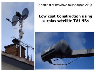
- 1. Sheffield Microwave round-table 2008 Low cost Construction using surplus satellite TV LNBs
- 2. Introduction Being a late recruit to analogue satellite TV back in the 1990’s, I missed the Squarial and the later bluecap LNB phase, instead starting off with an Amstrad SRD510 receiver, 60cm off-set mesh dish and Amstrad SLB-1 LNB. It was all very stylish, with a beautiful goose-neck feed arm fitted to the dish - and this the cheapest option then available. Even the programmes were interesting, so it was several years before curiosity overcame all else and the LNB assembly rivets were drilled out to allow a closer look. That first view of a Ku-band LNB innards was fascinating. It didn’t look at all ‘domestic’, but was nicely laid out with good quality components fitted to a pcb fabricated on a decent dielectric board. The LNB housing was a quality high pressure casting, as was the pcb top-side screen assembly - and all put together with screws, even if they were tap-tites. I liked the way you could follow the signal path so easily and they didn’t seem to skimp on gain, even in the front-end. Soon I was wondering what other LNBs were like, so when surplus units appeared cheaply at rallies, it was inevitable that some would be bought and striped down. Over a decade on, and I still can’t resist stripping these units down. It’s harmless and educational. Green even. A decade on, and LNBs have been put to many uses here. I tend to concentrate on the 3cm amateur band - if only to prevent a proliferation of antennas appearing on the roof-line. The current set-up is shown on the opening slide. Seperate 45cm mini-dishes are used side by side for Tx and Rx. On receive, it’s certainly very simple, with an LNB being used as an antenna-with-integral 20dB pre-amplifier. Even on transmit, an LNB is used. This time, just the housing, with a probe attached to the waveguide where a feed was once taken to the original pcb. To keep feeder losses low after the PA stage, this is located (along with its driver) on the feed arm to the LNB. With 3W at the dish focus, this set-up works very well - even at this poor QTH. What follows is a collection of amateur-radio re-uses for your spare or unwanted LNB. I have not included radio-astronomy projects, but it’s interesting to note that three LNBs and two dishes will allow a very nice interferometer to be constructed that will give good results on sun transit observations.
- 3. Ten uses for that spare satellite LNB Very cheap source of Gaasfets and mmic’s Unmodified! - Rx converter to 618 MHz Rx antenna with built-in 20 dB pre-amp 20 dB gain block at 10 GHz 40 dB wideband amplifier for 800 - 2000 MHz Rx converter using external high stab LO source Tx converter using external high stab LO source Tx/Rx converter using external high stab LO source Frequency multiplier for 24 GHz receiver/transceiver Hardcore (if you still have any of those old blue caps)
- 4. A brief history of the Sky (UK) LNB Before discussing these other LNB applications, it is worth looking at the evolution of this module. There is no point in looking for deep meaning here - everthing to do with the Sky product can be summed up in one word: expediency Not that there is anything wrong with that, I suppose. It has been a fascinating period of UK Tv broadcasting history.
- 5. Early (1990s) Ku-band UK LNB block diagram Single output Single 10 GHz LO (I/P = 10.950 - 11.700 GHz) Supply to V and H input amplifiers switched to select mode
- 6. Early (1990’s) single output UK Ku-band LNB This block diagram is pretty much universal for the single output LNBs to seen at this time - if there is a variation, it is that some of the Cambridge Industries units had three RF stages instead of the two. In all cases, the horizontal and vertical antennas fed seperate initial RF amplifiers (the days of magnetic polarisers now being over). The supply to these stages were switched to select the appropriate polarisation, and the outputs combined prior to feeding the second common RF amplifier. On some units, the antennas were fabricated onto the pcb itself, with that part of the board sandwiched between the front section of the horn feed and the rear, which was integrated into the screening casting. Other types were made with a single piece horn/waveguide. The feed to these were antenna probes mounted tangentially from the pcb, and fed through holes in the waveguide side [Trivia: What is interesting about these particular feeds, is that they were aligned in the same plane, with the polarisation determined by where they were placed relative to a shorting bar, aligned in the same orientation, across the waveguide. One antenna was spaced a quaterwave in front of the bar, and one a quarterwave behind. In this way, the front antenna only saw radiation from the front - the shorting bar acting as a reflector to these signals, whilst shadowing the antenna from reflections from the rear of the waveguide. The opposite applied to the rear antenna, which saw nothing from the front, because the shorting bar produced a shadow from that side whilst acting as a reflector to signals from the rear. To get the 90 degree polarisation shift for the rear antenna, the back of the waveguide was angled rather than made straight, so that the reflected signal underwent the required twist. Quite clever, really. Output from the common RF amplifier was fed through a band-pass filter in order to attenuate image signals to the following mixer, which for UK (Sky) use had a 10 GHz local oscillator. At the time, transmission was between 10.950 and 11.700 GHz, giving an IF of 950 - 1170 MHz. Mixers were either diode ring using schottky diodes, or the function was integrated into a common LO/mixer/IF amp mmic, often housed in a TO-5 metal can assembly. To avoid problems with strong terrestrial signals (in particular, cell phone systems) and loss in the feed cable, gain blocks were added into the IF output path from the mixer. These usually comprised of two mmic devices giving an overall 40dB or so of gain. The supply for the LNB was sent down the IF feed cable, and polarisation switching was signalled by changing the supply voltage from 14 to 18 volts (14v resulting in vertical polarisation).
- 7. Early dual O/P Ku-band LNB Single 10 GHz LO All stages are active - no switching required
- 8. Early dual output LNB In situations where more than one receiver might be use at any given time, both horizontal and vertically polarised signals needed to be translated to IF simultaneously, and dual output LNBs where available for this purpose. With these units, no polarisation switching was necessary, instead, the whole front end, image filter, mixer and IF amplifier stages where duplicated. The only common stage from an rf point of view was the local oscillator. With this arrangement, it was the satellite tuner that had to do the switching, so both IF feeds were fed to it.
- 9. Current single O/P Ku-band LNB Input V and H amplifiers voltage switched (I/P = 10.7 - 12.75 GHz) LO oscillators tone switched
- 10. Current single output dual band Ku band LNB As more channels became available, there was a need to extend the bandwidth of the Sky platform, which already consisted of several satellites closely located, Initially, the bottom end of the band was extended from 10.950 GHz down to 10.700 GHz and ‘extended’ single output LNBs appeared on the market. Interestingly, the LO frequency of these extended LNBs was also changed and dropped by the same amount (ie, down to 9.750GHz) so that the low end of the IF range remained at 950MHz. I assume this was done to avoid powerful signals in the cell phone band causing problems with the lower end down-converted satellite signals. . These new LNBs could be used with new tuners that covered the extended range, or old LNBs (with a 10GHz LO) and a switched converter installed to move the lower channels into an existing tuners now limited frequency range. Within a couple of years Sky were also able to use the higher 11.700 to 12.750GHz band, and another LNB change was necessary. This could have been achieved by allowing the IF frequency range to increase to 950 - 3.00GHz, but instead, it was achieved by using the existing IF frequency spread and switching the LNB LO frequency to generate a second group of frequencies across the same range. The second LO frequency seems to have been universally set at 10.600GHz right from the start. Voltage switching was still used to change polarisation, and tone switching introduced to control the choice of LO frequency. The standard is to select the lower 9.750GHz LO frequency when no tone is present, and to select the higher 10.600GHz LO frequency when a 22 KHz tone is superimposed on the LNB supply line.
- 11. Current dual output (Sky +) LNB
- 12. Current dual output (Sky +) LNB Unlike earlier dual output LNBs, the current versions have individually switched outputs. This is necessary because the application is a little differant. In any case, the minimum number of fixed assignment outputs would be four (to cater for all the combinations of polarisation and LO frequency). These days, dual output LNBs are used in the UK to serve Sky + systems, where one program can be recorded whilst another is simultaneously being watched, so one LNB output is independantly controlled by the video recorder and the other by the viewer. Within the LNB, there are four seperate front-ends These are: 1] Low-band horizontal polarisation 2] Low-band vertical polarisation 3] Hi-band horizontal polarisation and 4] Hi-band vertical polarisation There is some dual use of circuitry. For instance, the two vertical polarisation options above use the same RF pre-amplifiers, the output being split to feed seperate hi-band and low-band vertical polarisation mixers (and the same in the horizontal case). It is quite common to see three cascaded amplifier stages used in these units. The two low-band mixers are fed from the 9.750GHz LO and the two hi-band mixers are fed from the 10.600GHz LO. The four mixers are each followed by the usual 40dB or so of IF gain amplifiers. All the circuitry described so far is permanantly switched on. What the supply voltage detector and the tone detector circuits control on these units are the routing of single pole four position gaas switches on each of the two LNB output connectors.
- 13. Quad output LNB
- 14. Quad output LNB The only differance between this unit and the previous twin output version is that two more four-position gaas switches have been added to compliment the two extra LNB outputs, simply doubling the number of independant outputs available to four. However, when buying LNBs through ebay, beware that another possibility exists - four output units are available that are really intended for distribution systems. With these variants (apparantly refered to as ‘Quatro’ LNBs), the switching is dispensed with and each output has a defined role - just as the early two output LNBs had. This isn’t a problem, but it may save confusion when you come to connect it up.
- 15. Ten uses for that spare satellite LNB Very cheap source of Gaasfets and mmic’s Unmodified! - Rx converter to 618 MHz Rx antenna with built-in 20 dB pre-amp 20 dB gain block at 10 GHz 40 dB wideband amplifier for 800 - 2000 MHz Rx converter using external high stab LO source Tx converter using external high stab LO source Tx/Rx converter using external high stab LO source Frequency multiplier for 24 GHz receiver/transceiver Hardcore (if you still have any of those old blue caps)
- 16. Gaasfets Current production NEC NE4210S01 NEC NE3210S01 Mitsubishi MGF4941AL Gain: 13dB @ 12GHz Gain: 13.5dB @ 12GHz Gain: 13.5dB @ 12GHz NF: 0.5dB @ 12GHz NF: 0.35dB @ 12GHz NF: 0.35dB @ 12GHz Ptot: 165mW Ptot: 165mW Ptot: 50mW _________________________________ Replacement status ______________________________ NEC FHX05LG NEC FHX06LG Mitsubishi MGF4918D NEC FHX35LG NEC FHX14LG Gain: 10.5dB Gain: 10.5dB Gain: 9.5dB Gain: 10dB Gain: 13dB NF: 0.9dB NF: 1.1dB NF: 0.6dB NF: 1.2dB NF: 0.55dB Ptot: 180mW Ptot: 180mW Ptot: Ptot: 290mW Ptot: 180mW
- 17. Cheap source of Gaasfets At a minimum, an LNB will contain four Gaasfets. In addition to these front end devices, there may well be gaasfets used in the LO and mixer stages. Identification of the front-end devices can be time consuming. They are coded in a variety of ways, dependant on the manufacturer, who will usually be either Mitsubishi or NEC. The slide shows some common types with the three on the top line representing what to expect in current build. Note the low noise figures available. When used at the lower microwave amateur bands, expect all of these to be capable of 0.5/0.6dB noise figures. For types not shown, expect a none-too-quick visit to Google. Removal is best done with a heat gun. Static damage is a strong possibility if thoughtlessly done, however, if you ground the LNB or pcb, if it has been removed, by placing your hand on the casting or board as the devive is lifted away with tweezers, no problem should arise. Likewise, if storing in a metal box or conducting plastic bag, hold the box or bag in one hand, whilst dropping in the device with the tweezers in the other. This way, there is virtually no voltage differance between any of the items.
- 18. Mmic’s sourced from satellite LNBs These 6 pin SOT363 devices are widely used in ___________ LNBs (and are marked C1H and C1E) (C1H) Thomson 13553 ) O
- 19. Cheap source of mmic’s When it comes to the IF section, expect a slight variation between LNB types. Early models tended to use a couple of mmic’s in tandem. There was then a period in the 90’s when this function was combined with the mixer and LO, the whole thing being fabricated as one single package, either metal can TO-5 fitted to the reverse side of the pcb (very common), or an epoxied sub- pcb fitted to the component side. By the end of the 90’s, discrete mmic’s came back in style, whilst currently it is quite usual to see an mmic followed by an npn device as the final stage. NEC mmic devices are very common - particularly the uPC2712TB, which appears still to be current despite the design being a decade or so old. It can be found fitted in either super minimold or SOT-363 packaging, and is marked with the code ‘C1H’. Gain is 20dB + up to a couple of GHz, and it runs off a 5v supply rail. Biasing is simple enough as the next slide for the uPC2709TB shows. If the lead spacing is a little daunting, then look for older LNBs which use the cross lead packaging shown in the next but one slide. Beware though, if you are buying these devices seperately that they are now noticeably more expensive than the newer types.
- 20. uPC2709TB (C1E)
- 21. Mmic’s with larger pin spacings Agilent N10 = INA-10386 (26dB @ 1.5GHz) Minicircuits A01 = MAR-1 (15.5dB @ 1GHz) A02 = MAR-2 (11dB @ 2GHz) A03 = MAR-3 (11.5dB @ 2GHz) A04 = MAR-4 (8dB @ 1GHz) A05 = MAR-8 (22.5dB @ 1GHz)
- 22. Ten uses for that spare satellite LNB Very cheap source of Gaasfets and mmic’s Unmodified! - Rx converter to 618 MHz Rx antenna with built-in 20 dB pre-amp 20 dB gain block at 10 GHz 40 dB wideband amplifier for 800 - 2000 MHz Rx converter using external high stab LO source Tx converter using external high stab LO source Tx/Rx converter using external high stab LO source Frequency multiplier for 24 GHz receiver/transceiver Hardcore (if you still have any of those old blue caps)
- 23. Unmodified LNB used as a narrowband converter... I can hear the shouts of derision already, but I add this use not altogether tongue in cheek. Rather like the super-regen single device receiver, it is interesting just what can be achieved with one of these when the wind is in your favour. My introduction to such a converter occured only this year, when Mike G8VXN visited with an LNB fed scanner receiver. I assumed that this was being used as part of a wideband link, and even when he commented that the scanner had an ssb detector, I didn’t think that it had any relevence to his microwave exploits - but it did. When I put up a narrow band signal, he netted in, and although the signal drifted through the passband quickly, and the note didn’t sound very clean, it was there nontheless. Later, I thought that I would duplicate this test, and several unhacked LNBs were collected ready to test. All my testing was done with LNBs having a 9.750GHz LO, remembering that these have an extended LF band edge of 10.700GHz which tend to result in little image filter attenuation at 10.368GHz. This meant that the IF was going to be about 618MHz. I intially used a locked signal generator and diode ring mixer to act as a direct conversion receiver. Results were quite supprising. About half of the LNBs had poor LO phase noise characteristics and resulted in very rough notes. But some were much better, and in most cases the drift settled down to quite low levels after a quarter of an hour or so. I found that on the better units that I could monitor the whole of the keying portion of the local 10GHz beacon without problem. This meant, for instance, that I could readily listen to rain-scatter doppler effects on such a receiver, and that this would be quite interesting to many an otherwise non 10GHz equiped amateur. It didn’t take long to build a 618 to 18MHz converter that would enable an HF receiver to be used as a replacement for the signal generator driven receiver. I have found that the single output LNBs that the Lidl supermarket store sold for £4 a few years ago was amongst the good units, as was the current Thomson quad output LNB. When used with an SDR-14 software defined radio covering 190 KHz in one sweep, an unmodified LNB can be used as a simple beacon (propagation) monitoring set-up quite effectively, as long as you have a local beacon which you can use to calibrate the received frequency. Infact in this case, you don’t even need the 618 to 18MHz converter because you can use the ‘direct’ input on the SDR-14 to harmonic sample directly at 618 MHz, though you need a band-pass filter at this frequency to select the 618MHz component from all the rest. The maths is as follows: SDR-14 sampling frequency = 66.6667 MHz 9th harmonic of Fsampling = 600 MHz So set SDR-14 software to receive at 618 - 600 = 18 MHz (for 10368.000 MHz) Usually the LNB LO is within a few hundred KHz of 9.750GHz - but not always! It was very interesting after I gave this talk to meet Brian, GM8BJF. Brian has added a probe into the LO cavity of his LNB in order to injection lock the oscillator, and the results sounded very good, needing about 1mW to achieve reliable lock.
- 24. Ten uses for that spare satellite LNB Very cheap source of Gaasfets and mmic’s Unmodified! - Rx converter to 618 MHz Rx antenna with built-in 20 dB pre-amp 20 dB gain block at 10 GHz 40 dB wideband amplifier for 800 - 2000 MHz Rx converter using external high stab LO source Tx converter using external high stab LO source Tx/Rx converter using external high stab LO source Frequency multiplier for 24 GHz receiver/transceiver Hardcore (if you still have any of those old blue caps)
- 25. Antenna with integral 20 dB amplifier
- 26. Rx antenna with built-in 20dB pre-amp This re-use of a satellite LNB provides an easy and reliable way to ensure a low noise figure front end, though you are going to need two dishes if you want to transmit as well as receive. I have yet to find an LNB that couldn’t be modified, but inevitably, some are easier than others. They all involve taking the signal away from the last RF amplifier stage just before it is fed to the image filter. On some of the older units, it’s as easy as drilling a hole through the pcb at an appropriate point and fitting an sma socket to the ground plane side of the board. The first slide is such an example, and uses an Amstrad SLB-1. With the SLB-1, most of the casting behind the pcb is flat with no detailing, so it is an easy matter when drilling through the pcb to continue into the casting to mark the spot. This can then be drilled through with the board removed and the hole enlarged to allow the sma socket to poke through. Looking at the second slide, you can see where the hole was drilled through the board and some of the track removed to the image filter. A 1p capacitor was added to provide a DC block. Each RF amplifier seems to give about 10dB gain, so expect 20dB overall gain from the SLB-1. This is enough to allow several metres of RG223 sma back to back interconnection to join the LNB to the receive converter. Expect about 3dB/m loss in the RG223 tail. Also expect the background noise to rise noticeably as the supply is switched on to the LNB. If you are outside, alternately point the LNB from the sky to the ground, and expect the background noise level to rise. If you are inside, bring the LNB up to a flourescent light. There should be a noticeable rise in noise output. This type of LNB, with it’s circular horn feed should be used with either a prime focus dish, or an offset dish where the vertical diameter is greater than the horizontal diameter (so that when you look at the dish from the LNB mounting point, you see a circular section). If you use this LNB to illuminate the later mini-dish, where the horizontal diameter is greater than the vertical one, you will not get optimum dish illumination, and the gain will be less than you expect. Note that for 3cm horizontal polarisation, you need 18v applied to the LNB - unless you choose to rotate the unit 90 degrees, that is.
- 27. Component side
- 28. Cambidge Industries G88 used as an antenna with integral 20dB amplifier The next two slides show the modifcation made to a G88 LNB. This was designed to be used with a mini-dish, and so has an eliptical horn section to illuminate the dish evenly. It also has choke sections within the horn to define the pattern more sharply and reduce the amount of dish over-spill. With this LNB, the width of the pcb is not much greater than the waveguide section, which also runs parallel to the pcb (the antennas in this case being probes fitted tangentially to the pcb), so the output cannot be taken so easily as the previous example. However, there is plenty of clear board area where the (unwanted) image filter is, and one solution is to add some thin copper tape over the filter to act as a groundplane. Even if the tape were not electrically connected to the groundplane, there would be enough capacitive coupling through the board to produce a reasonable ‘virtual groud’. In practice, though, when the screeen section is bolted back onto the main casting, it is likely to contact the copper tape in many places, so it’s a little accademic. With this solution (see second slide), the semi-rigid feed (RG405) comes away from the assembly at the rear, and it is necessary to file a slot in the screen to let the cable through. Also, it’s a good idea to remove the LO and mmic IF components to assist the leads placement. Insulating the back end of the lead also prevents the possibility of shorts to supply rail portions of the pcb track. Again, a 1pF capacitor is added as a DC block. If you have no small value capacitors, take another LNB apart and take one from that. For instance, you will see on the G88 that the ring mixer is fed via a DC blocking capacitor from the image filter, so you could use that. As before, if you mount the LNB in it’s intended orientation, you will require an18v supply to obtain horizontal polarisation. This can be a bit of a pain, which is why my dishes are mounted 90 degrees round from their normal use, to allow a 12v supply to be applied. Common to all these modifications that use an RG405 tail, it is quite sensible to use flexiform cable in place of the more usual semi-rigid, which is still rigid enough to rip track away from the pcb if it gets accidentilly pushed. Farnell sell it (under the name ‘Quickform’ and some of us were lucky enough pick some of this up at the Sunday trading session. The use of sma connectors here is very sensible, by the way.
- 30. Copper tape added to give large ground- plane area
- 31. Thomson 13553 LNB A further variation on assembly method is to be seen with this Thomson unit. At first glance, it looks very similar to the previous G88, but on closer inspection, you discover that the pcb is fitted with the ground-plane uppermost. This allows the RF output to be taken from the back of the pcb, and a connector can be sweated on, or some semi-rigid soldered tangentially from the board, as shown in the next slide. A disaddvantage with this unit is that the outer cover is glued into place, and you end up destroying it to gain entry - it’s a very thin material.
- 32. Thomson 13553 LNB 10 - 14v supply = vertical polarisation 15 - 18v supply = horizontal polarisation
- 33. Ten uses for that spare satellite LNB Very cheap source of Gaasfets and mmic’s Unmodified! - Rx converter to 618 MHz Rx antenna with built-in 20 dB pre-amp 20 dB gain block at 10 GHz 40 dB wideband amplifier for 800 - 2000 MHz Rx converter using external high stab LO source Tx converter using external high stab LO source Tx/Rx converter using external high stab LO source Frequency multiplier for 24 GHz receiver/transceiver Hardcore (if you still have any of those old blue caps)
- 34. Ku-band 20dB gain block Another useful re-use is to take the previous example and add a connector on the input, in place of the antenna or antenna probe to produce a wideband amplifier with 20dB gain. In the next slide of a Cambridge Industries AE31, the horn section and waveguide have been sawn off to give complete access to the back of the LNB pck. Since this unit uses probe antennas, no extra hole has be drilled since it is already there. However, the hole through the casting has to be opened up. A DC blocking capacitor is an absolute ‘must’. Short the gate down to ground (with the supply running) and the gaasfet will be destroyed. This is because the bias circuit used does not seem to have current limiting in these this fault situation - a common feature, I have noticed. It is not always easy to fit this capacitor in because the probe is often brought through very close to the amplifier gate connection. It is amazing that with a couple of these gain blocks used as line amplifiers, you can use large runs of RG223 cable from the antenna! There also versions of this style of LNB that have three cascaded RF amplifiers, so you can have 30dB of gain with these modified units.
- 35. 20dB gain block Cambridge Industries AE31
- 36. Ten uses for that spare satellite LNB Very cheap source of Gaasfets and mmic’s Unmodified! - Rx converter to 618 MHz Rx antenna with built-in 20 dB pre-amp 20 dB gain block at 10 GHz 40 dB wideband amplifier for 800 - 2000 MHz Rx converter using external high stab LO source Tx converter using external high stab LO source Tx/Rx converter using external high stab LO source Frequency multiplier for 24 GHz receiver/transceiver Hardcore (if you still have any of those old blue caps)
- 37. 40dB wideband amplifier for 800 - 2000 MHz For LNBs that have discrete IF amplifiers (ie, that do not use an IC which combines the mixer, LO and IF amplifier functions) it is very easy to produce a 40dB wideband amplifier that will be flat between 800 - 2000MHz. A few will remain flat right down to 200MHz or so, and an example of this is the Thomson 13553, which is shown on the next slide. With this unit, the (gaasfet) mixer feeds a uPC2711TB mmic gain block followed by an NPN BFG. In all cases, locate the mixer, and see how it is coupled into the IF amplifier. With a diode ring mixer type, this is easy enough, and the DC block coupling capacitor will be easy enough to find. If you are lucky, you will be able to drill a hole through the board on the mixer side of the capacitor, and come away from the back of the pcb and through the casting, To isolate the mixer, just cut the track between the capacitor and the mixer. Returning to the Thomson unit, this is modified by removing the the thin outer screen, which is pressed and silicon-rubbered into place, Since this will be damaged anyway, the easiest way to do this is to push a screwdriver through it somewhere in the middle (it is suprisingly thin) and prise away from the main cast housing. Then remove the inner screen, which is fastened by four or five scews. The pcb below will then come away, once you have unsoldered the IF output at the end of the board. Locate the gaasfet mixer, and remove the device. You can then drill through the board at the point that had connected to the mixer drain. Slip the board onto its backing screen, and drill through onto the plate to marl where the output will be. The plate can then be drilled seperately with a hole big enough to allow the sma connector (if that is what you are using) to poke through. It is easy enough to sweat an sma connector to the back of the pcb.. The result of these modifications is a compact little amplifer, the output of which is the original ‘F’ connector. You will need to insert 8 - 15v at some point on the output, but this need only be a choke with a 10n capacitor down to ground. Although the noise figure will only be 3 - 4dB, these modified units make simple mast head amplifiers at 1296 MHz.
- 38. Wide-band amp using Thomson LNB type 13553 O )
- 39. Ten uses for that spare satellite LNB Very cheap source of Gaasfets and mmic’s Unmodified! - Rx converter to 618 MHz Rx antenna with built-in 20 dB pre-amp 20 dB gain block at 10 GHz 40 dB wideband amplifier for 800 - 2000 MHz Rx converter using external high stab LO source Tx converter using external high stab LO source Tx/Rx converter using external high stab LO source Frequency multiplier for 24 GHz receiver/transceiver Hardcore (if you still have any of those old blue caps)
- 40. 3cm Rx converter using external high stab LO An LNB can be used as a 3cm converter - either with or without the integral antenna. The modifications to the LNB are much easier than the production of the external hi-stab LO source... What follows is a trek through the various types of LNBs that have appeared in the UK since the 1990s, and the considerations that should be given with regard to the choice of IF frequency. Achieving the hi-stab LO source is not covered here - it is part of the second powerpoint presentation. The choice of mixer type is interesting. Very early LNBs used schottky diode pair half ring mixers (and they are still used today), but in the early and mid 1990s many UK LNBs used a combined mixer/LO/IF amp integrated circuit made by Anadigics. These were house in a metal T0-3 case fitted to the ground-plane side of the pcb, so are very easy to spot. Ratheon also produced similar items, but packaged them differantly. In the last five years or so, gaasfet mixers seem to have come into style. The next slide shows examples of all of these.
- 41. 3cm receive converter with external (high stab) LO Dual Diode mixer mmic mixer Gaasfet mixer
- 42. Thomson 13553 LNB - gaasfet mixer example This LNB seems to be current build, or at least still available from suppliers. As seems always to be the case, the device used as the mixer is identicle to that used in the RF amplifier preceding it. The mixer is operated passively - there is no drain dc supply, though on this particular board component pads as fitted to allow this to be done, which is interesting. However, negative bias is applied to the gate, and is on all the LNBs using this type of mixer that I have seen. It is an easy matter to insert an external LO, since the point at which the hi and low internal lo feeds combine is right on the centre line of the board, and easy to locate. The internal LOs can be isolated by removing their DC blocking capacitors at this point. After drilling a hole through the board and fitting an sma socket on the rear side, it the two stubs that are left by removing the blocking capacitors should be cut away - it is all too easy to inadvertantly end up with a quarterwave stub that shorts out the LO path!. With this Thomson LNB, the groundplane side of the pcb faces away from the main casing, so the sma connector needs to poke through a suitably drilled hole in the pcb back-plate. When I measured the amount of LO injection needed, it was just as much as you would require for a diode mixer, and perhaps a little more. A level of about +10dBm seemed about right.
- 43. Gaasfet Mixer Mixer is passive - ie, there is no drain dc supply
- 44. Anadigics AKD12000 combined mixer/LO/IF amp integrated circuit It has taken me ten years to find out who made the AKD12000 chip and to find a datasheet for it, and I guess this is the real reason that the next slide was added! I even cut the the lid off this TO-3 housed device to see if a microscope might reveal its identity. Another reason for persevering with this device is that there is so many of them about, and also, if you were building your own front-end, it might be easier to use this part than anything else. The one potential problem is that the LO interconnect is via a single pin, and internal feedback is applied to produce oscillation when a transmission line is connected (the line is used to couple into a dielectric puck which dominates the resonant frequency). Removing the puck is not enough to stop the AKD12000 oscillating, so you need to be careful when using an LNB with this part with an external LO. However, if you drill a hole through the pcb as close to the IC end of the track as is possible, given that you have allow room to solder a connector or semi-rigid cable, and you move the terminating resistors at the end of the transmission line track right up to the IC pin, then you should find that the device remains stable. A sample that was modified this way seemed to work well enough. At some point, it would be interesting to see what frequency range you can make this mixer work over. Could it be used in a 5.6GHz receiver, for example?. All that IF gain would be very useful if it could. Note that this (series of) device uses positive and negative supplies, so I assume it is fabricated using gaasfet technology. The Raytheon RAY40 device, which I can’t find information about, but is to be found in a few early LNBs, only requires a positive supply voltage. There is quite a bit of IF sloping below 800 MHz, and the picture shows that despite their size several etched inductors were used on the chip, and I suspect that these form part of the IF high-pass filtering.
- 45. Combined LO, mixer and IF amp ICs
- 46. Cambridge Industries G88 - diode mixer example The G88 LNB makes a tidy 3cm front-end where you require an antenna socket rather than to use the internal antenna. In this situation, the first job is to find your hacksaw. Cut away both the input horn and it’s accompanying waveguide - you don’t need to go right down to the bottom of the waveguide. Both RF and LO I/P connectors will fit on the centre line, so a little bit of the waveguide wall projecting away from the housing will be OK. This LNB uses probe antennas, so there is already a hole through the pcb that an sma socket can be soldered, but to avoid gaasfet failure if the the gate is short-circuited to ground, fit a 1pF DC blocking capacitor. Although it would be nice to use the horizontal antenna probe hole (the one closest to the centre of the casting), so that a 12v supply could be used, and the dish mounted in its intended orientation, it is better to use the ‘vertical’ one right at the end of the board, otherwise the connector will end up very close to the LO connector. The LO input is connected via the DC blocking capacitor to the diode mixer common terminal. This is is a pair of schottky diodes housed in an SOT-23 package. Note that on the circuit diagram, I’ve indicated it being fitted direct to the SOT-23 device, but it’s actually easier to drill a hole through the track/board right on the centre line. Then remove the capacitor that feeds in the right-hand LO and cut the excess track away from the left-hand LO. Also remove the two LO transistors to stop them oscillating. This produces a really neat front end.
- 47. Cambridge Industries G88 - diode mixer example Inject ext O ( LO
- 48. RF I/P LO I/P IF O/P (and +Vcc) G88/G96 LNB RF LO IF o / o
- 49. Other considerations The next few slides refer to other considerations that should be thought about. On the first one is a plot of LNB output versus frequency up to 1 GHz. Above 800MHz, the plot is flat with the output level at maximum. However, because of the high-pass filtering used i the IF section, the output falls below this frequency until at 300MHz and below, it is 30dB down and into the analyser noise floor. Using this particular LNB (Amstrad SLB-1) at an IF of 144MHz would not be very satisfactory. Some of the newer LNBs have a flat response response well below 800 MHz, so it is worth checking, if a 144MHz IF is prefered. Another reason for using a high IF is that the image filtering requirement becomes easier - in fact, the internal image filter alone is likely to be enough with an IF of 700 MHz and above (a later slide shows 30dB image rection for an IF of 768MHz). A more subtle issue is the response of that internal image filter. On all dual band LNBs that I have measured, the response at 3cm is still - just, on the flat portion of the curve, These LNBs have work down to 10.700MHz, so we are lucky. The older, single band LNBs (with an LO frequency of 10GHz) only have work down to 10.950GHz, and you find that at 3cm you are well down the curve. This is shown in the second and third next slides. All is not lost, though, if you wish to use a 10GHz LO LNB. The image filter response can be move down in frequency by a few percent quite easily. Just add dielectric loading to the track side of the filter. A Sellotape ‘sticky-pad’ should suffice.
- 50. Typical LNB IF output response 0 10 20 30 40 50 dB 0 500 1000MHz
- 51. Image filter response: Grundig AUN3S
- 52. Image filter response - Amstrad SLB1
- 53. Effect of dielectric loading of Image filter (Amstrad SLB1)
- 54. Ten uses for that spare satellite LNB Very cheap source of Gaasfets and mmic’s Unmodified! - Rx converter to 618 MHz Rx antenna with built-in 20 dB pre-amp 20 dB gain block at 10 GHz 40 dB wideband amplifier for 800 - 2000 MHz Rx converter using external high stab LO source Tx converter using external high stab LO source Tx/Rx converter using external high stab LO source Frequency multiplier for 24 GHz receiver/transceiver Hardcore (if you still have any of those old blue caps)
- 55. Tx converter using external hi-stab LO source With LNBs that use a diode based mixer, there is no reason why a signal on 3cm should not be generated, but compared to the rx converter case there is one complication, and that is that following the mixer (and image filter) you need to reverse the gaasfets and reconfigure the bias and supply connections. This inevitably involves some hacking away at the pcb track. LNBs using gaasfet mixers should be capable of successful modification also. The amount of IF drive required is about 1mW, so there should be no need for extra IF gain. On the next slide, one of the mmic amplifiers is shown ‘turned around’ to act as a buffer, but this is really too much hassle to be worth while - just route a wire directly from the ‘F’ connector to the DC blocking capacitor that sits between the mixer and the first IF mmic amplifier (having first at least removed the mmic) . However, it does make sense to use one stage of RF amlification at 3cm to both buffer and amplify the output from the image filter. In the G88 example shown, it is easy to reverse the bias and supply rails to what was originally the common RF amplifier stage, because they run parallel to each other in places (see top right hand corner of the pcb shown in the next slide. The most obvious place to cut the tracks is just after the decoupling capacitor that follows the fan shaped quarterwave stub short-circuit on the gate and drain feeds). To output from the RF buffer, drill a hole in the place marked at the RF intersection of the two input gaasfets and the common stage. No extra DC blocking capacitor is required because there is already one there. Again, this makes for a very tidy arrangement. Remember to remove the two unwantedinput gaasfets from the board, and don’t forget to turn round the wanted device... Experience tends to show that one still gets 5 - 6dB of gain from a ‘turned-around’ stage without any rematching. The external LO feed is applied as before on the RX converter drawings. Due to running short of time, the Tx converter shown used the existing LO, and with that it was possible to see what the carrier leak and image responses were. As can be seen, the carrier leak was 10dB down and the image 30dB down when using an LO frequency of approximately 9.600GHz (ie, IF frequency of 768MHz).
- 56. Tx converter using G88/G96 LNB o o
- 57. Using internal LO set to 9650 MHz IF input at 717 MHz (level -10 dBm) Wanted output = 10368 MHz (at -10 dBm) Image output = 8933 MHz
- 58. Ten uses for that spare satellite LNB Very cheap source of Gaasfets and mmic’s Unmodified! - Rx converter to 618 MHz Rx antenna with built-in 20 dB pre-amp 20 dB gain block at 10 GHz 40 dB wideband amplifier for 800 - 2000 MHz Rx converter using external high stab LO source Tx converter using external high stab LO source Tx/Rx converter using external high stab LO source Frequency multiplier for 24 GHz receiver/transceiver Hardcore (if you still have any of those old blue caps)
- 59. Tx/rx converter (transverter) combination using a dual input LNB The complexity of having seperate LNBs for Tx and Rx converting can be avoided by using a two input LNB, where all the front- end circuitry is duplicated, though you do end up with quite a few connections being made to the LNB. The slides that follow show a Cambridge Industries LNB, and is what I currently use on 3cm from the home QTH. As one of the photographs show, dielectric loading of the image filters had to be done because this LNB had a 10GHz LO, and as we have already found, this invariably implies a lower RF frequency edge of 10.950 rather than the later 10.700GHz units. This is almost inevitable because of the scarcity of modern dual output Sky + units. If you follow the LO tracing, you can see that a Wilkinson divider has been used to split the LO signal to the two mixers. Just drill a hole through the board at the point where the LO feeds the splitter - in this case right on the splitter to avoid the board screen casting from shorting out the connected (so also remove the adjacent series resistor). An LNB modified in this way works well, but ensure that the dielectric loading is mechanically sound - you don’t want the gain dropping off (particularly on Tx) because the loading material has fallen off. This is why ‘sticky-pads’ are a good choice for this purpose.
- 60. Cambridge Industries AE2 LNB Rx IF O/P LO Rx I/P Tx IF I/P Tx O/P
- 61. Rx image < Tx RF O/P BPF < LO Rx image BPF
- 62. Ten uses for that spare satellite LNB Very cheap source of Gaasfets and mmic’s Unmodified! - Rx converter to 618 MHz Rx antenna with built-in 20 dB pre-amp 20 dB gain block at 10 GHz 40 dB wideband amplifier for 800 - 2000 MHz Rx converter using external high stab LO source Tx converter using external high stab LO source Tx/Rx converter using external high stab LO source Frequency multiplier for 24 GHz receiver/transceiver Hardcore (if you still have any of those old blue caps)
- 63. X3 or X4 multiplier for 24 GHz converter Many of the up or down converter blocks available at the moment for 24Ghz require an LO drive at half frequency, which would be 11.520GHz for a 1008MHz IF (a suitable frequency for a double conversion front-end driven directly from a 10 MHz reference oscillator). 11.520GHz falls within the pass-band of any of the UK market LNBs, so the image filter can be used to select this frequency if the amplifier that precedes it is driven into clipping at a sub harmonic. One of the early LNBs, with a narrower pass-band is ideal for this purpose. There is enough gain in the two front-end RF amplifiers, without modification, at 2.8 or 3.8GHz to simply input power at these frequencies at about 3dBm. On the graphs shown, you might expect the wanted level to be 30dB higher than all others, though I did get 40dB on two others that I measured but was lazy to record. In effect, this is one of the 20dB gain blocks discussed earlier, but with the output taken after the image filter instead of before. The level at 11.520GHz was about 3 - 4dBm.
- 64. X3 or x4 multiplier using overdriven LNB LO = 11.520 GHz for 24 048 MHz converter with 1008 MHz 1st IF X 3 multiplier X 4 multiplier Ie, LO drive = 3.840 GHz Ie, LO drive = 2.880 GHz l l l l l l l l l l l
- 65. Ten uses for that spare satellite LNB Very cheap source of Gaasfets and mmic’s Unmodified! - Rx converter to 618 MHz Rx antenna with built-in 20 dB pre-amp 20 dB gain block at 10 GHz 40 dB wideband amplifier for 800 - 2000 MHz Rx converter using external high stab LO source Tx converter using external high stab LO source Tx/Rx converter using external high stab LO source Frequency multiplier for 24 GHz receiver/transceiver __________ Putting it all together Hardcore
- 66. Two examples of equipment based on modified LNB units My portable receiver is shown in the next slide. It is dual conversion and uses a 10MHz ovened reference oscillator. To avoid having to build lots of VHF multipliers, a Pye F496 transmitter was used (with the PA disconnected). This would normally run at x 36 multiplication, but it will also accept a lower frequency input and multiply by 48, in this case to 480MHz, which is slightly out of band. Output from the pre-driver is about 1W, but this was turned down to 0.5W and used to drive a simple x5 diode multplier using a 1N4148. This feeds a x4 multiplier using an LNB front end amplifier run into clipping and used to feed a pipe-cap filter tuned to 9.600GHz. A second amplifier (actually the other half of a dual input LNB) is used to bring the level up to 10mW, which is enough to drive a G88 LNB used as a converter, as descibed earlier. The second IF converter is fairly conventional, and use an LNB... Similar to this receiver is a second unit that was used as a low power beacon transmitter used at 10368.000 MHz. On this occasion, a Philips FR5000 VHz transmitter driver unit was used to multipiy a 14.4MHz 2ppm reference oscillator up to 172.8MHz. This was further multiplied by 2 before being fed into a dual LNB with one front-end section run into clipping, and the 5th harmonic selected using a pair of pipe-cap filters. The output was then amplified up to 10mW using the second front-end section. Both these units are described in more detail in the second series of slides.
- 67. 3cm receiver using Pye M296 tx as LO multiplier
- 68. Simple 10 dBm source at 10 368 MHz