Download to read offline

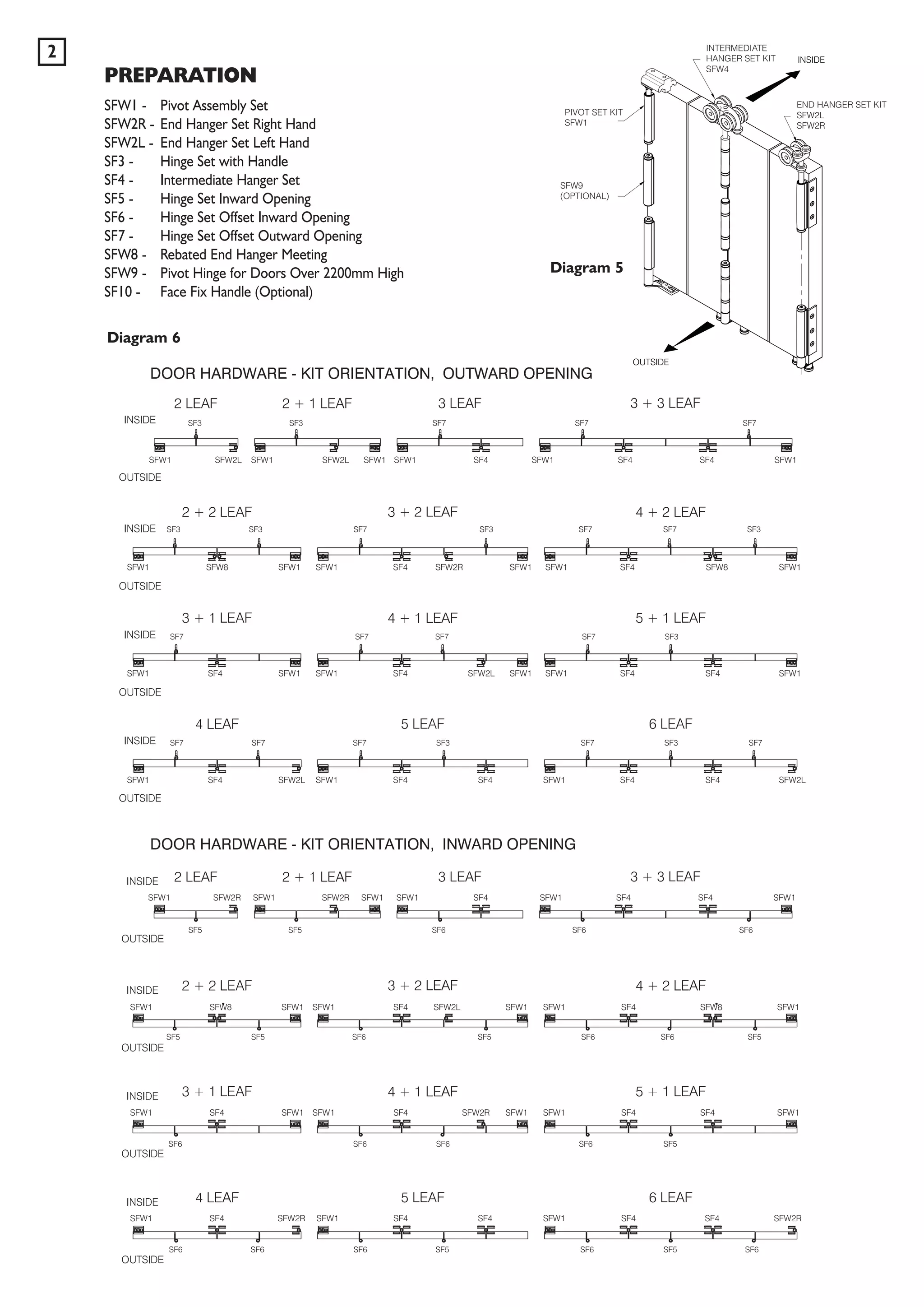
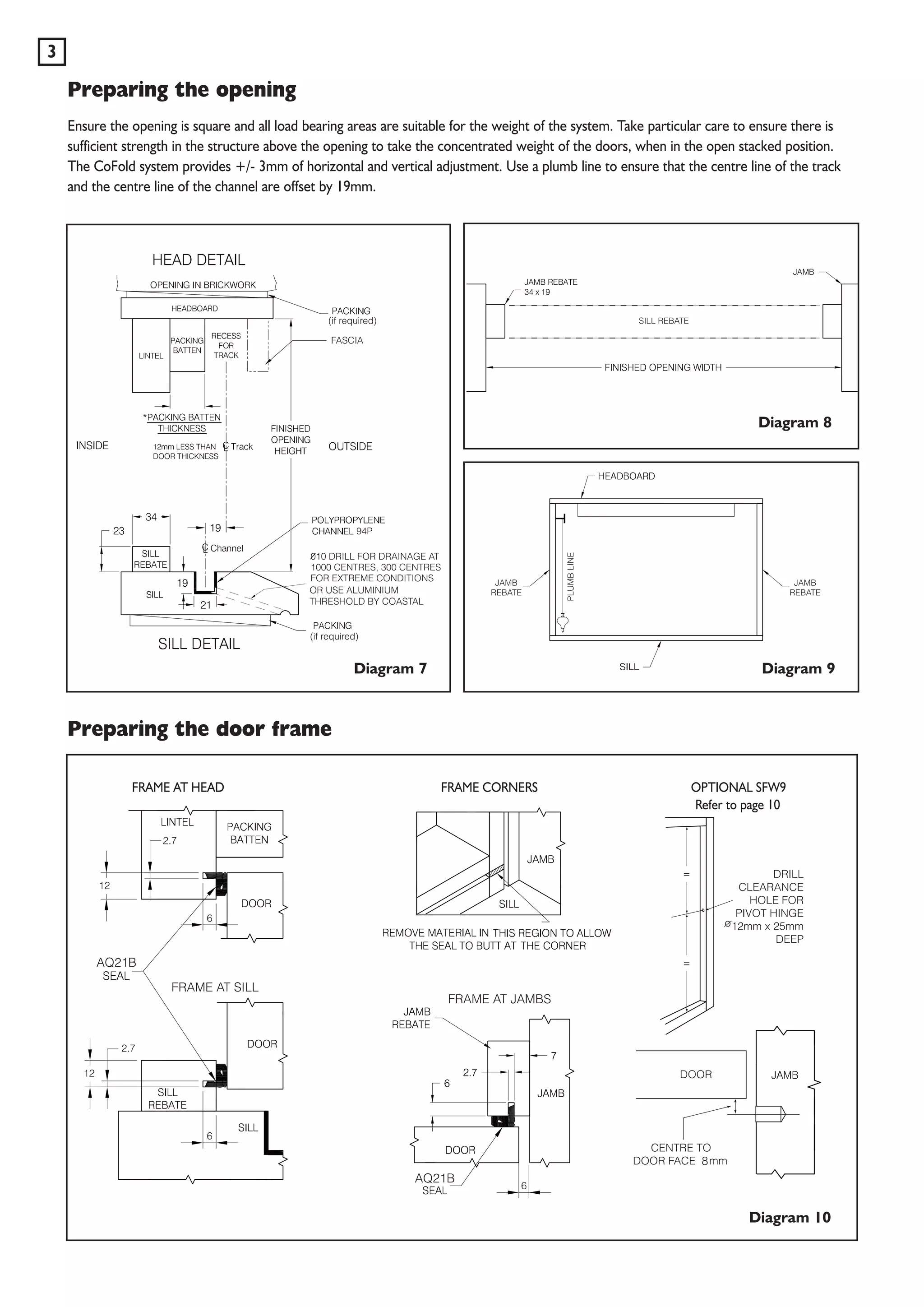
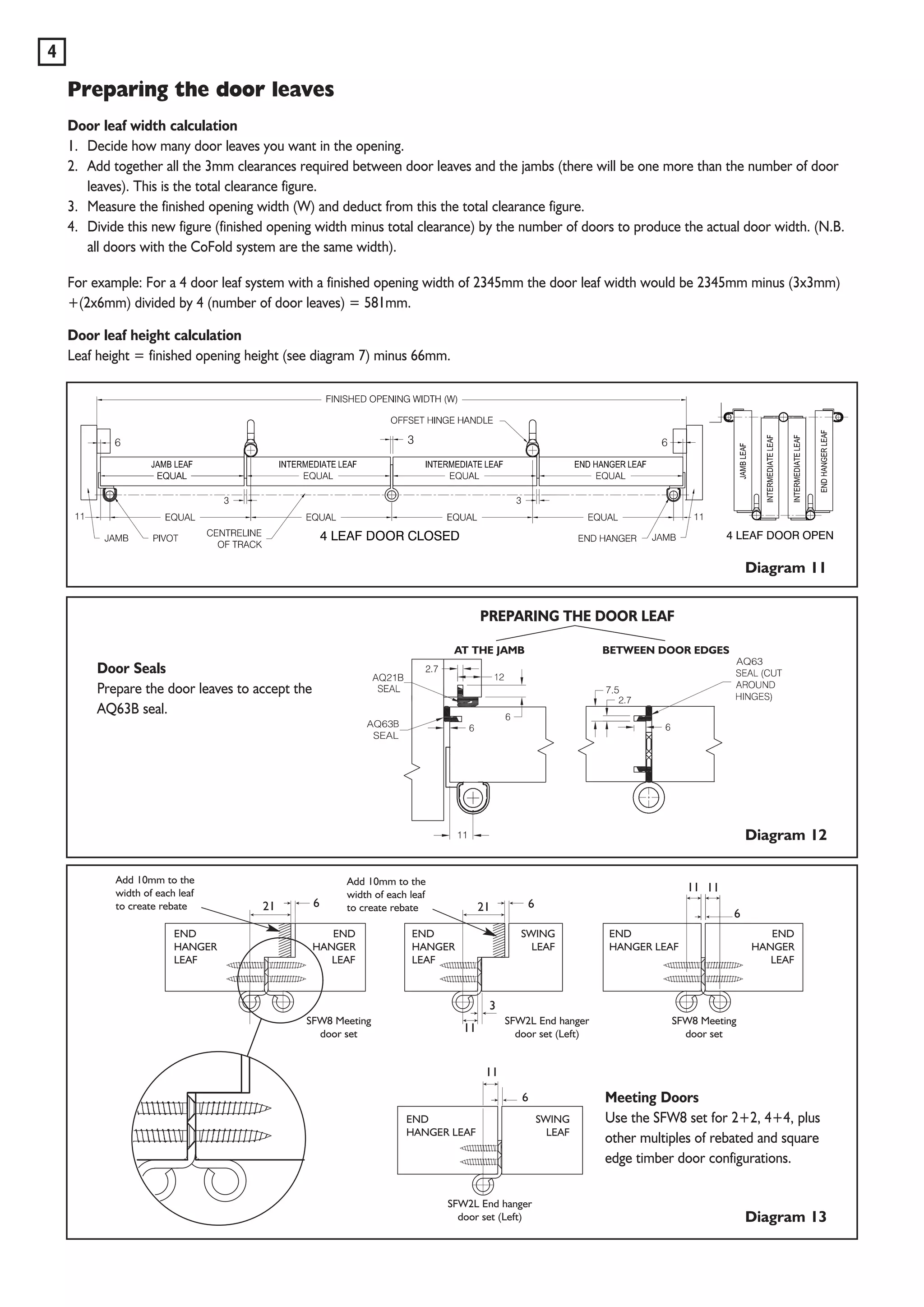


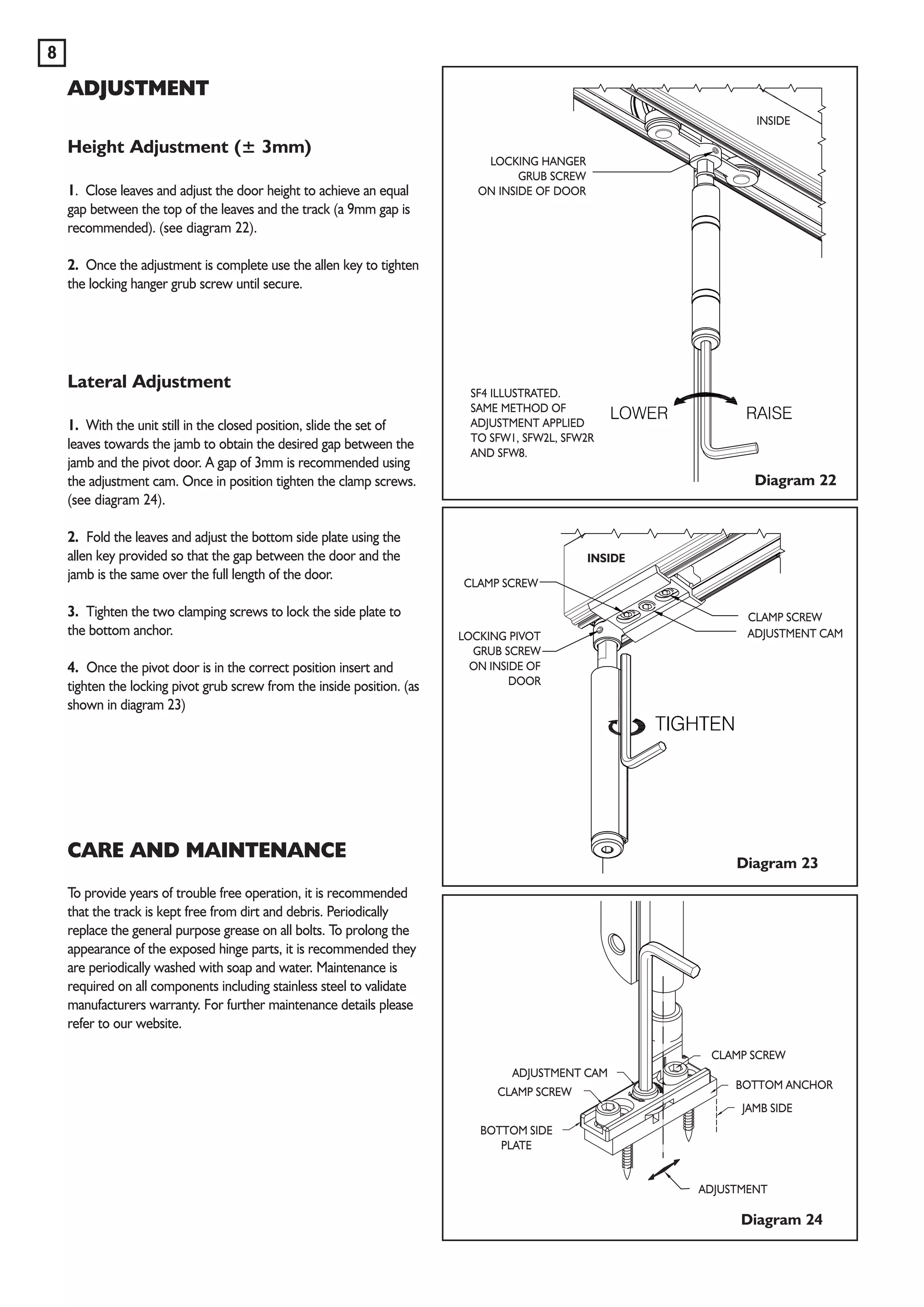


This document provides detailed fitting instructions for the cofold non-mortice system for top hung exterior folding doors, covering specifications such as maximum dimensions and weight limits. It outlines the preparation of the opening, door leaf calculations, hardware positioning, and installation steps, including adjustments for alignment and maintenance guidelines. Additionally, it emphasizes ensuring the structural integrity of the installation area and provides diagrams for reference.


