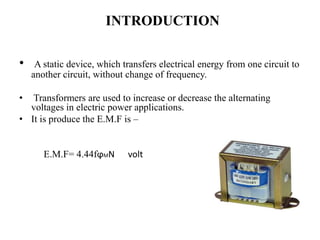
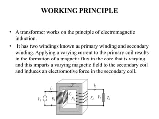
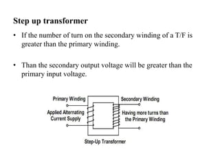
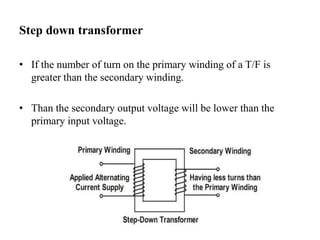
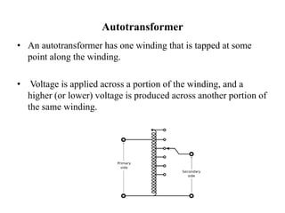
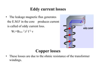
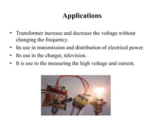
Department of Mechanical Engineering 2016-17
Seminar on
“ TRANSFORMER ”
SUBMITTED TO: SUBMITTED BY:-
MR. SAURABH KUMAR SINGH ARJUN RANA
MR. VINOD KUMAR GAUTAM ROLL NO-1473640903
MR. ANKIT KUMAR SRIVASTAV MECHANICAL ENGINEERING
MR. PANKAJ YADAV
RAJKIYA ENGINEERING COLLEGE,
AZAMGARH
CONTENTS
• Introduction
• Working principle of transformer
• Types of transformer
• Transformer Efficiency
• Losses of transformers
• Advantages
• Disadvantages
• Applications
INTRODUCTION
• A static device, which transfers electrical energy from one circuit to
another circuit, without change of frequency.
• Transformers are used to increase or decrease the alternating
voltages in electric power applications.
• It is produce the E.M.F is –
E.M.F= 4.44fϕMN volt
WORKING PRINCIPLE
• A transformer works on the principle of electromagnetic
induction.
• It has two windings known as primary winding and secondary
winding. Applying a varying current to the primary coil results
in the formation of a magnetic flux in the core that is varying
and this imparts a varying magnetic field to the secondary coil
and induces an electromotive force in the secondary coil.
TYPES OF TRANSFORMER
• Step-up transformer
• Step-down transformer
• Auto transformer
• Instrument transformer
Step up transformer
• If the number of turn on the secondary winding of a T/F is
greater than the primary winding.
• Than the secondary output voltage will be greater than the
primary input voltage.
Step down transformer
• If the number of turn on the primary winding of a T/F is
greater than the secondary winding.
• Than the secondary output voltage will be lower than the
primary input voltage.
Autotransformer
• An autotransformer has one winding that is tapped at some
point along the winding.
• Voltage is applied across a portion of the winding, and a
higher (or lower) voltage is produced across another portion of
the same winding.
Instrument transformer
Current transformer
• A current transformer is step-up transformer.
• It is a series connected measurement device designed to
provide a current in its secondary coil proportional to the
current flowing in its primary.
Voltage transformer
• A voltage transformer is a step-down transformer used along
with a low range voltmeter for measuring a high voltage.
• The primary winding is connected across the high voltage
supply and the secondary winding to the voltmeter.
Transformer Efficiency
•Transformer efficiency is defined as the ratio of output to
input power.
%100
in
out
P
P

%100


lossout
out
PP
P

Types of losses incurred in a transformer:
Copper I2R losses
Hysteresis losses
Eddy current losses
Therefore, for a transformer, efficiency may be calculated using the following:
%100
cos
cos
x
IVPP
IV
SScoreCu
SS





Losses of transformers
• Core losses
• Hysteresis losses
• Eddy current losses
• Copper losses
 Hysteresis losses
• During magnetization and demagnetization ,
due to hysteresis effect, some energy
losses in the core called hysteresis loss.
Wh=Bmax
1.6 fv watt.
Eddy current losses
• The leakage magnetic flux generates
the E.M.F in the core produces current
is called of eddy current loss.
We=Bmax
2.t2 f 2 v
Copper losses
• These losses are due to the ohmic resistance of the transformer
windings.
Advantages of transformers
• Transformers are provide to required voltage.
• it is operate to the high voltage and low voltage.
• It can be used to prevent DC from passing from one circuit
to the other.
Disadvantages
• Transformer can’t step up or step down the level of DC
voltage or DC Current.
• Its costly in high voltage system.
Applications
• Transformer increase and decrease the voltage without
changing the frequency.
• Its use in transmission and distribution of electrical power.
• Its use in the charger, television.
• It is use to the measuring the high voltage and current.
Thanking you

Transformer

  • 1.
    Department of MechanicalEngineering 2016-17 Seminar on “ TRANSFORMER ” SUBMITTED TO: SUBMITTED BY:- MR. SAURABH KUMAR SINGH ARJUN RANA MR. VINOD KUMAR GAUTAM ROLL NO-1473640903 MR. ANKIT KUMAR SRIVASTAV MECHANICAL ENGINEERING MR. PANKAJ YADAV RAJKIYA ENGINEERING COLLEGE, AZAMGARH
  • 2.
    CONTENTS • Introduction • Workingprinciple of transformer • Types of transformer • Transformer Efficiency • Losses of transformers • Advantages • Disadvantages • Applications
  • 3.
    INTRODUCTION • A staticdevice, which transfers electrical energy from one circuit to another circuit, without change of frequency. • Transformers are used to increase or decrease the alternating voltages in electric power applications. • It is produce the E.M.F is – E.M.F= 4.44fϕMN volt
  • 4.
    WORKING PRINCIPLE • Atransformer works on the principle of electromagnetic induction. • It has two windings known as primary winding and secondary winding. Applying a varying current to the primary coil results in the formation of a magnetic flux in the core that is varying and this imparts a varying magnetic field to the secondary coil and induces an electromotive force in the secondary coil.
  • 5.
    TYPES OF TRANSFORMER •Step-up transformer • Step-down transformer • Auto transformer • Instrument transformer
  • 6.
    Step up transformer •If the number of turn on the secondary winding of a T/F is greater than the primary winding. • Than the secondary output voltage will be greater than the primary input voltage.
  • 7.
    Step down transformer •If the number of turn on the primary winding of a T/F is greater than the secondary winding. • Than the secondary output voltage will be lower than the primary input voltage.
  • 8.
    Autotransformer • An autotransformerhas one winding that is tapped at some point along the winding. • Voltage is applied across a portion of the winding, and a higher (or lower) voltage is produced across another portion of the same winding.
  • 9.
    Instrument transformer Current transformer •A current transformer is step-up transformer. • It is a series connected measurement device designed to provide a current in its secondary coil proportional to the current flowing in its primary. Voltage transformer • A voltage transformer is a step-down transformer used along with a low range voltmeter for measuring a high voltage. • The primary winding is connected across the high voltage supply and the secondary winding to the voltmeter.
  • 10.
    Transformer Efficiency •Transformer efficiencyis defined as the ratio of output to input power. %100 in out P P  %100   lossout out PP P  Types of losses incurred in a transformer: Copper I2R losses Hysteresis losses Eddy current losses Therefore, for a transformer, efficiency may be calculated using the following: %100 cos cos x IVPP IV SScoreCu SS     
  • 11.
    Losses of transformers •Core losses • Hysteresis losses • Eddy current losses • Copper losses  Hysteresis losses • During magnetization and demagnetization , due to hysteresis effect, some energy losses in the core called hysteresis loss. Wh=Bmax 1.6 fv watt.
  • 12.
    Eddy current losses •The leakage magnetic flux generates the E.M.F in the core produces current is called of eddy current loss. We=Bmax 2.t2 f 2 v Copper losses • These losses are due to the ohmic resistance of the transformer windings.
  • 13.
    Advantages of transformers •Transformers are provide to required voltage. • it is operate to the high voltage and low voltage. • It can be used to prevent DC from passing from one circuit to the other.
  • 14.
    Disadvantages • Transformer can’tstep up or step down the level of DC voltage or DC Current. • Its costly in high voltage system.
  • 15.
    Applications • Transformer increaseand decrease the voltage without changing the frequency. • Its use in transmission and distribution of electrical power. • Its use in the charger, television. • It is use to the measuring the high voltage and current.
  • 16.