Downloaded 395 times
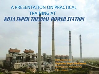
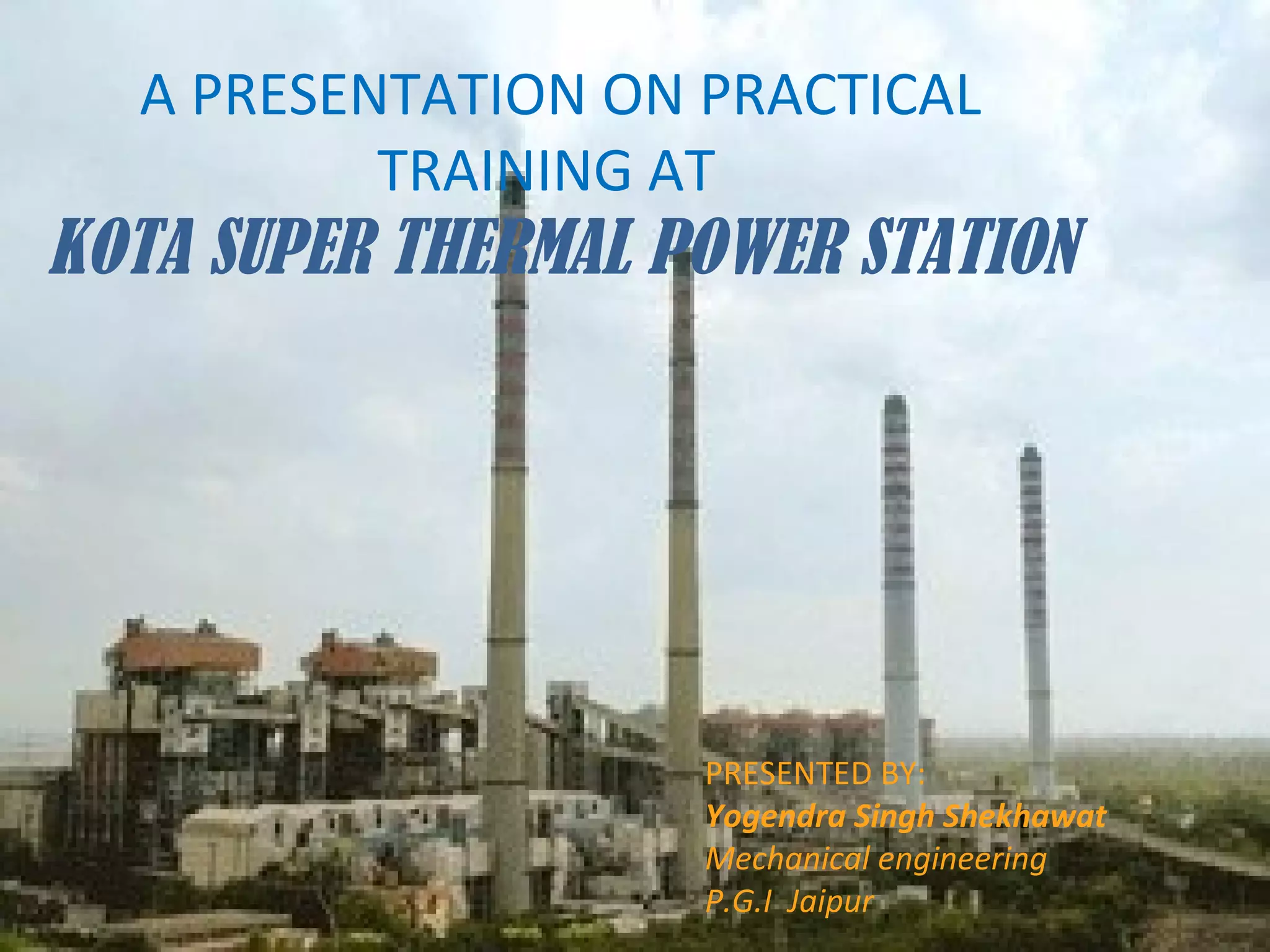
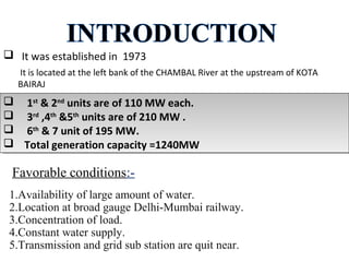
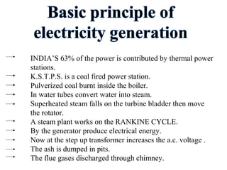
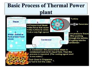
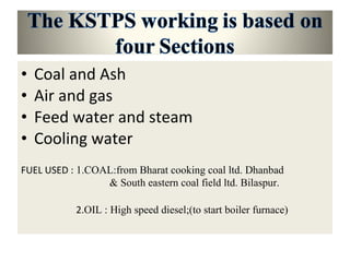
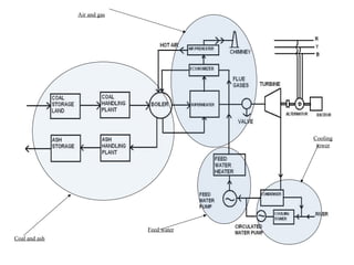
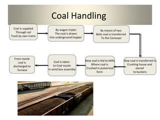


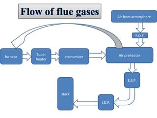
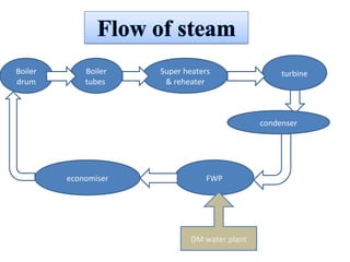
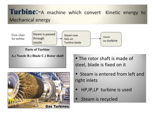
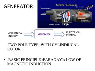


This document summarizes a presentation about the Kota Super Thermal Power Station in India. It describes that the power station was established in 1973 along the Chambal River and has a total generation capacity of 1,240MW from its 7 units. The power station uses coal as its fuel, which is pulverized and burned to convert water into high-pressure steam that drives turbines connected to generators. The station employs various processes and equipment to handle coal, produce steam, generate electricity, treat water, and dispose of ash in an environmentally-safe manner. It provides a valuable practical training opportunity for engineering students to learn about large-scale power generation.


