AN
INDUSTRIAL TRAINING PRESENTATION
ON
KOTASUPER THERMAL POWER STATION
Submitted by :-
Name – VINAY MAHAVAR
Roll No. – 23/
Batch - B-6
Department of Electrical Engineering
RAJASTHAN TECHNICAL UNIVERSITY, KOTA
Submitted to:-
Establishment Year:It was established in 1983.
Location: It is located on the left bank of the Chambal River,
upstream of Kota Barrage.
Unit Capacities:
1st & 2nd units: 110 MW each
3rd, 4th & 5th units: 210 MW each
6th & 7th units: 195 MW each
Total Generation Capacity: The total generation capacity is 1240
MW (calculated as 110+110+210+210+210+195+195=1240
MW).
Favorable Conditions:
Abundant quantity of clean cooling water.
Good transport facility.
INRODUCTION OF THERMAL POWER PLANT :-
4.
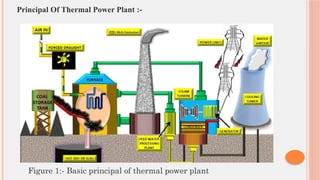
Principal Of ThermalPower Plant :-
Figure 1:- Basic principal of thermal power plant
5.
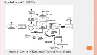
Technical Layout OfKSTPS :-
Figure 2:- Layout Of Kota super Thermal Power Station
6.
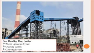
Coal Handling PlantSection
Wagon Unloading System
Crushing System
Conyeing System
7.
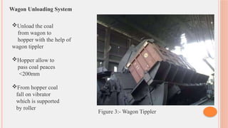
Wagon Unloading System
Unloadthe coal
from wagon to
hopper with the help of
wagon tippler
Hopper allow to
pass coal peaces
<200mm
From hopper coal
fall on vibrator
which is supported
by roller
Figure 3:- Wagon Tippler
8.
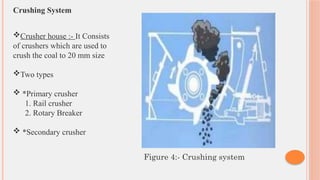
Crushing System
Crusher house:- It Consists
of crushers which are used to
crush the coal to 20 mm size
Two types
*Primary crusher
1. Rail crusher
2. Rotary Breaker
*Secondary crusher
Figure 4:- Crushing system
9.
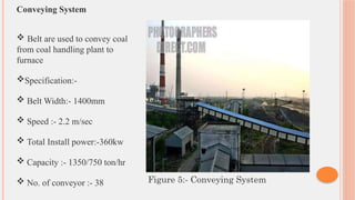
Conveying System
Beltare used to convey coal
from coal handling plant to
furnace
Specification:-
Belt Width:- 1400mm
Speed :- 2.2 m/sec
Total Install power:-360kw
Capacity :- 1350/750 ton/hr
No. of conveyor :- 38 Figure 5:- Conveying System
10.
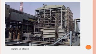
Boiler
A closedvessel where water under pressure is converted into steam.
Hot water or steam is used to transfer heat to a process.
Always designed to absorb the maximum amount of
heat released during combustion
Furnace: The primary part of the boiler where fuel is burned to liberate
heat energy.
Energy conversion
Chemical Energy of fuel → Thermal Energy by combustion
Super-heater
Consists of agroup of tubes.
These tubes are heated by the hot combustion gases as they pass from
the furnace to the chimney, which increases the temperature of the
steam.
The primary function of the super-heater is to remove moisture from
the steam leaving the boiler tubes.
A component that increases the temperature of steam, making it superheated,
by utilizing heat from the hot flue gases.
This process enhances the efficiency of the steam turbine and reduces the risk
of condensation within the turbine, preventing potential damage.
13.
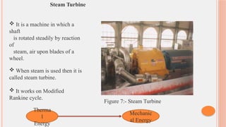
Steam Turbine
Itis a machine in which a
shaft
is rotated steadily by reaction
of
steam, air upon blades of a
wheel.
When steam is used then it is
called steam turbine.
It works on Modified
Rankine cycle.
Therma
l
Energy
Mechanic
al Energy
Figure 7:- Steam Turbine
14.
Economizer
• Economizer isa device which recover heat from the flue gases on
their way to chimney.
• It increase the 10-12% efficiency of the plant.
15.
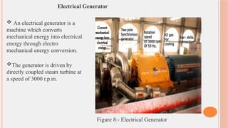
Electrical Generator
Anelectrical generator is a
machine which converts
mechanical energy into electrical
energy through electro
mechanical energy conversion.
The generator is driven by
directly coupled steam turbine at
a speed of 3000 r.p.m.
Figure 8:- Electrical Generator
16.
Water Treatment Plant
Pressure Filter: Removes "undissloved impurities" from raw water. This
suggests a general filtration step for larger particles or suspended solids.
Carbon Filter: Removes excess chlorine from clarified water. Chlorine is often
used as a disinfectant but can be corrosive or problematic in certain industrial
processes.
D.M. Plant (Demineralization Plant): Removes dissolved impurities from
clarified water. This is a crucial step for producing high-purity water by
removing ions and minerals.
Water Quality Monitoring: The conductivity, pH, and silica content of the
treated water must be checked regularly. These parameters are critical for
preventing scaling, corrosion, and other issues in systems like boilers.
17.
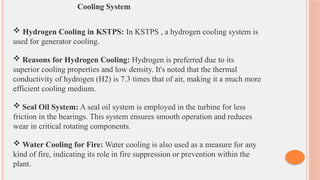
Cooling System
HydrogenCooling in KSTPS: In KSTPS , a hydrogen cooling system is
used for generator cooling.
Reasons for Hydrogen Cooling: Hydrogen is preferred due to its
superior cooling properties and low density. It's noted that the thermal
conductivity of hydrogen (H2
) is 7.3 times that of air, making it a much more
efficient cooling medium.
Seal Oil System: A seal oil system is employed in the turbine for less
friction in the bearings. This system ensures smooth operation and reduces
wear in critical rotating components.
Water Cooling for Fire: Water cooling is also used as a measure for any
kind of fire, indicating its role in fire suppression or prevention within the
plant.
18.
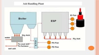
Ash Handling Plant
Subdivision of a Plant The plant can be subdivided into 3 sub-plants:
1) Fuel and ash plant: Handles the incoming fuel and the initial stages of ash.
2) Air and Gas plant: Manages the air supply for combustion and the exhaust
gases.
3) Ash disposal and dust collection plant: Deals with the collection and disposal
of ash and dust.
Ash Composition in Thermal Plants
In thermal plants, 25% of the ash is furnace bottom ash, and 75% is pulverized
fuel ash (also known as fly ash).
Fly Ash Removal
An Electrostatic Precipitator is used in the ash handling plant to remove fly ash.
This device is crucial for environmental control, capturing fine particulate matter