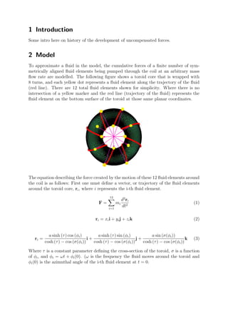
This document describes a model of a fluidic toroidal drive. The model develops parametric equations to define the wrapping of a toroidal core and uses Newtonian mechanics to calculate the forces induced on the core from the symmetrical flow of fluid elements around it. For certain numbers of turns in the wrapping, an uncompensated thrust is produced that could enable propulsion. Figures 1-3 show contours of the x, y, and z directional forces on the core over time for different numbers of turns in the wrapping using 500 fluid elements in the simulation.
Transformation matrices can be used to describe that at what angle the servos need to be to reach the desired position in space or may be an underwater autonomous vehicle needs to reach or align itself with several different obstacles inside the water.
Digital signatures are often used to implement electronic signatures, a broader term that refers to any electronic data that carries the intent of a signature, but not all electronic signatures use digital signatures. In some countries, including the United States, India, and members of the European Union, electronic signatures have legal significance.
In this presentation the following topics are covered:
- Active debris removal techniques
- Tethered space tug
- Mathematical model
- Numerical simulation and analysis
- Results and conclusion
Presentation for the 5th Eucass - European Conference for Aerospace Sciences - Munich, Germany, 1-4 July 2013.
Prediction of aerodynamic characteristics for slender bluff bodies with nose ...vasishta bhargava
the numerical approach is used to verify the aero/hydrodynamic performance of different
geometries of nose cones. Computational methods predict the flow characteristics fairly accurately in order to validate
the data obtained from experiments. The simulation involves muzzle velocity that range from 5m/s to 25 m/s i.e. 1.69 to
8.4 x 10⁵
and calculated for the different angle of attack, -10 to 20 degrees, to demonstrate the flow behavior around the
shells. Nosecone is the most forward section of any slender moving bodies which are used in rockets, guided missiles,
submarines, aircraft drop tanks and aircraft fuselage to reduce the aerodynamic or hydrodynamic drag. The basic
geometry of bluff body is cylinder with variant nosecone shapes such as flat and tapered head, with moderate to low
taper ratios and conical head.
Experimental flow visualization for flow around multiple side-by-side circula...Santosh Sivaramakrishnan
This paper deals with Flow visualization of multiple side by side circular cylinders of varying cross sections at Reynolds numbers from 50-200. An experimental setup for this purpose has been designed and described in the paper.
The International Journal of Engineering and Science (The IJES)theijes
The International Journal of Engineering & Science is aimed at providing a platform for researchers, engineers, scientists, or educators to publish their original research results, to exchange new ideas, to disseminate information in innovative designs, engineering experiences and technological skills. It is also the Journal's objective to promote engineering and technology education. All papers submitted to the Journal will be blind peer-reviewed. Only original articles will be published.
DYNAMIC RESPONSE OF SIMPLE SUPPORTED BEAM VIBRATED UNDER MOVING LOAD sadiq emad
In this thesis, an experimental and numerical study of dynamic deflection and dynamic bending stress of beam-type structure under moving load has been carried out. The moving load is constant in magnitude and travels at a uniform speed. The dynamic analysis of beam-type structure is done by taking three different concentrated loads (4, 6 and 8) kg , each one of them travels at three different uniform speeds (0.15, 0.2 and 0.25) m/s .
International Journal of Engineering and Science Invention (IJESI)inventionjournals
International Journal of Engineering and Science Invention (IJESI) is an international journal intended for professionals and researchers in all fields of computer science and electronics. IJESI publishes research articles and reviews within the whole field Engineering Science and Technology, new teaching methods, assessment, validation and the impact of new technologies and it will continue to provide information on the latest trends and developments in this ever-expanding subject. The publications of papers are selected through double peer reviewed to ensure originality, relevance, and readability. The articles published in our journal can be accessed online.
Application of DRP scheme solving for rotating disk-driven cavityijceronline
International Journal of Computational Engineering Research (IJCER) is dedicated to protecting personal information and will make every reasonable effort to handle collected information appropriately. All information collected, as well as related requests, will be handled as carefully and efficiently as possible in accordance with IJCER standards for integrity and objectivity.
A study-to-understand-differential-equations-applied-to-aerodynamics-using-cf...
toroidwork07-12-2012
1. Model of a Fluidic Toroidal Drive
Martin Jones
MARS44 CONSULTING, LLC
July 14, 2012
Abstract
We have determined parametric equations for the geometrical curve that defines
the wrapping of a toriodal core. Using the trajectory of the wrapping or fluid
flow, a Newtonian model has been developed for calculating the forces induced on
a specifically wrapped toriodal core (although other wrappings may be applied to
this methodology). It has not been necessary to use the equations of fluid motion to
calculate the Newtonian forces induced by fluid elements arranged symmetrically
around the axis of rotation of the core because it was not required to calculate the
dynamics of the fluid rather than the forces induced by imposed kinematics. A
few ‘special’ numbers of turns for the wrapping concerned were found to produce
an uncompensated thrust that can be used for propulsion.
1
2. 1 Introduction
Some intro here on history of the development of uncompensated forces.
2 Model
To approximate a fluid in the model, the cumulative forces of a finite number of sym-
metrically aligned fluid elements being pumped through the coil at an arbitrary mass
flow rate are modelled. The following figure shows a toroid core that is wrapped with
8 turns, and each yellow dot represents a fluid element along the trajectory of the fluid
(red line). There are 12 total fluid elements shown for simplicity. Where there is no
intersection of a yellow marker and the red line (trajectory of the fluid) represents the
fluid element on the bottom surface of the toroid at those same planar coordinates.
The equation describing the force created by the motion of these 12 fluid elements around
the coil is as follows: First one must define a vector, or trajectory of the fluid elements
around the toroid core, ri, where i represents the i-th fluid element.
F =
12
i=1
mi
d2
ri
dt2
(1)
ri = xii + yij + zik (2)
ri =
a sinh (τ) cos (φi)
cosh (τ) − cos (σ(φi))
i +
a sinh (τ) sin (φi)
cosh (τ) − cos (σ(φi))
j +
a sin (σ(φi))
cosh (τ) − cos (σ(φi))
k (3)
Where τ is a constant parameter defining the cross-section of the toroid, σ is a function
of φi, and φi = ωt + φi(0). (ω is the frequency the fluid moves around the toroid and
φi(0) is the azimuthal angle of the i-th fluid element at t = 0.
3. 3 Results
The Figures (1-3) show a contour of the forces in the x, y, and z directions versus the
number of turns in the winding of the tube around the toroid that carries the fluid (water
in this case) and the time. For a pump that rates at about 4 kg/s mass flow rate, the
model predicts the following results. In time, 4 periods are shown (the water circulates
4 times around the toroid). Force is in Newtons.
4 Future Work
Future work begs the question of space-time structure around this toroid. The same
methodology employed previously can be applied to the Einstein field equations to derive
the dynamic space-time structure caused by the moving fluid. Furthermore, once the
kinematics of the fluid are imposed, any space-time structure should be able to be derived
and vice-versa.
5 Acknowledgment
Thank you to Dan Winter for funding to accomplish these results. Also thank you to
both William Donavan and Winter for discussions and guidance during the development
of this model.
3
4. Figure 1: Shows the contour of the x-Force for time and number of turns on the torus.
This simulation used 500 fluid elements.
4
5. Figure 2: Shows the contour of the y-Force for time and number of turns on the torus.
This simulation used 500 fluid elements.
5
6. Figure 3: Shows the contour of the z-Force for time and number of turns on the torus.
This simulation used 500 fluid elements.
6