Time Modulated ArrayAntenna
Dr. Suman Nelaturi
Assistant Professor
Department of ECE
NIT Kurukshetra
2.
Time Modulated ArrayAntenna
θ - Direction of Radiation
fc - Carrier Frequency
d - spacing between the elements
β - Wave number
Un(t) - Periodic Modulation function
applied to nth array element
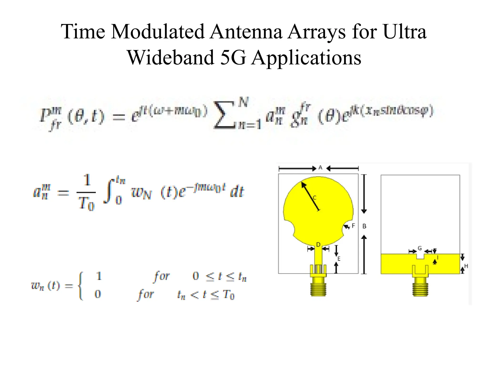
The Electromagnetic Wave Radiated by TMA is
The Fundamental Structure of TMA
Time Sequence of the nth array element
3.
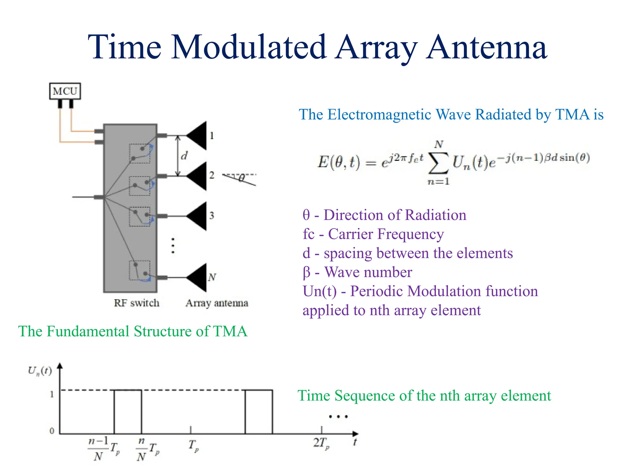
Time Modulated ArrayAntenna
RF Switch Activation Patterns define 4 Principal Operational modes for TMAs
1. Pulse Shifting (PS)
2. Variable Aperture Size (VAS)
3. Unidirectional phase center motion (UPCM)
4. Bidirectional phase center motion (BPCM)
4.
Time Modulated ArrayAntenna
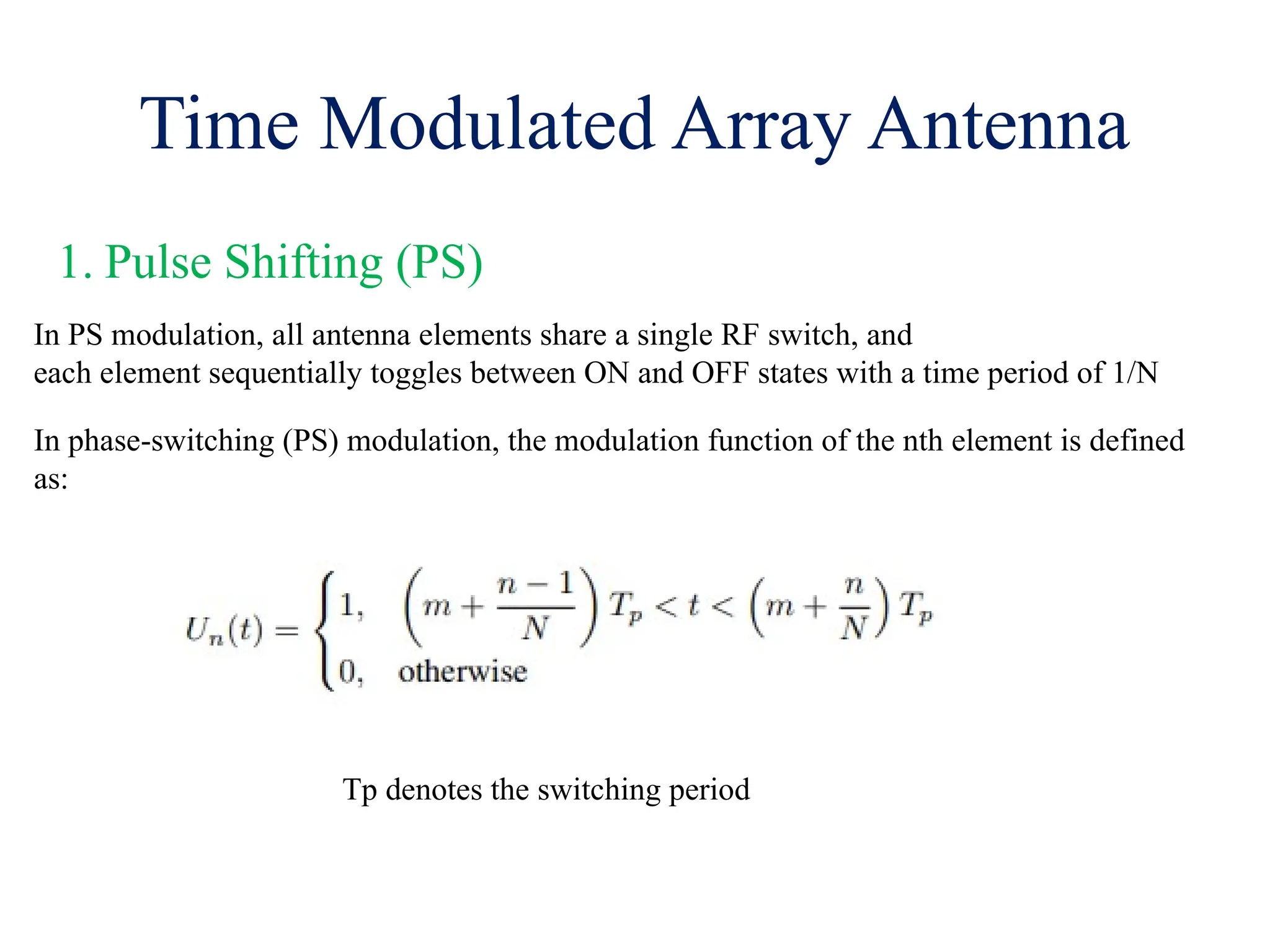
1. Pulse Shifting (PS)
In PS modulation, all antenna elements share a single RF switch, and
each element sequentially toggles between ON and OFF states with a time period of 1/N
In phase-switching (PS) modulation, the modulation function of the nth element is defined
as:
Tp denotes the switching period
5.
Time Modulated ArrayAntenna
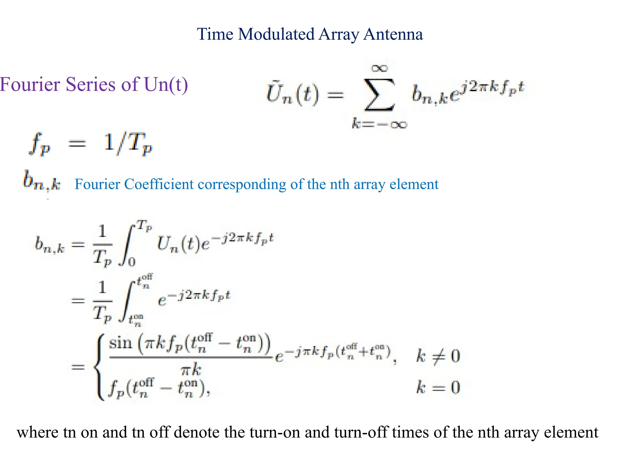
Fourier Series of Un(t)
Fourier Coefficient corresponding of the nth array element
where tn on and tn off denote the turn-on and turn-off times of the nth array element
6.
Time Modulated ArrayAntenna
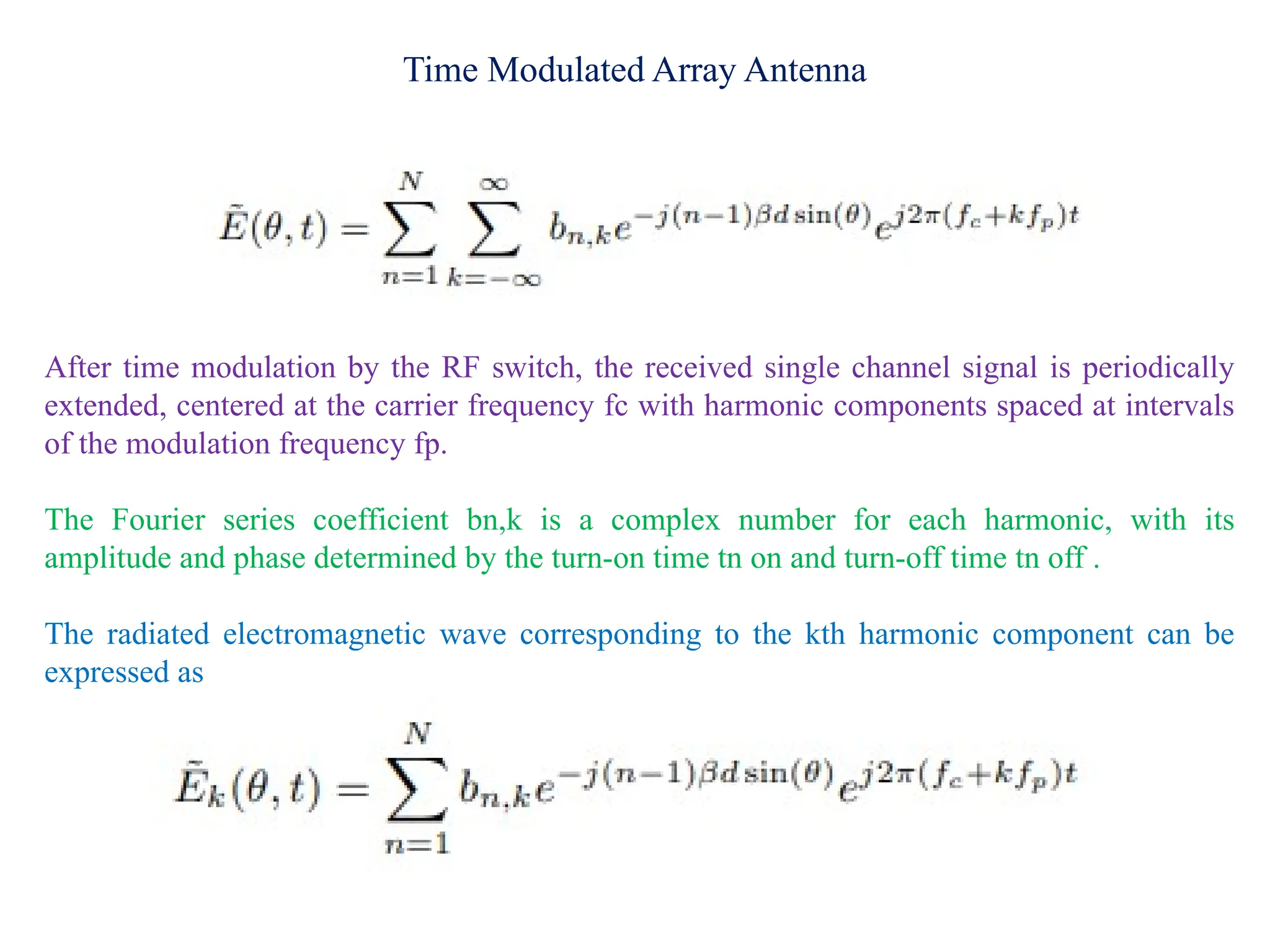
After time modulation by the RF switch, the received single channel signal is periodically
extended, centered at the carrier frequency fc with harmonic components spaced at intervals
of the modulation frequency fp.
The Fourier series coefficient bn,k is a complex number for each harmonic, with its
amplitude and phase determined by the turn-on time tn on and turn-off time tn off .
The radiated electromagnetic wave corresponding to the kth harmonic component can be
expressed as
7.
Time Modulated ArrayAntenna
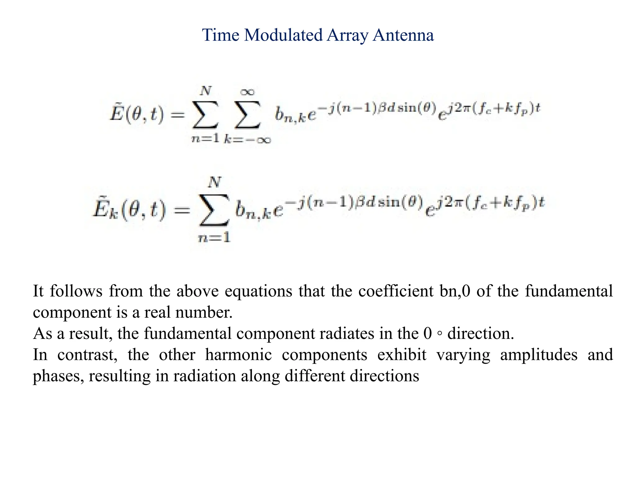
It follows from the above equations that the coefficient bn,0 of the fundamental
component is a real number.
As a result, the fundamental component radiates in the 0 ◦ direction.
In contrast, the other harmonic components exhibit varying amplitudes and
phases, resulting in radiation along different directions
8.
Time Modulated ArrayAntenna
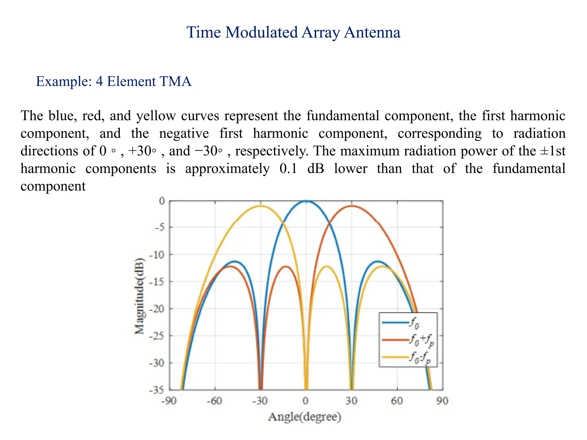
Example: 4 Element TMA
The blue, red, and yellow curves represent the fundamental component, the first harmonic
component, and the negative first harmonic component, corresponding to radiation
directions of 0 ◦ , +30◦ , and −30◦ , respectively. The maximum radiation power of the ±1st
harmonic components is approximately 0.1 dB lower than that of the fundamental
component
9.
Time Modulated ArrayAntenna
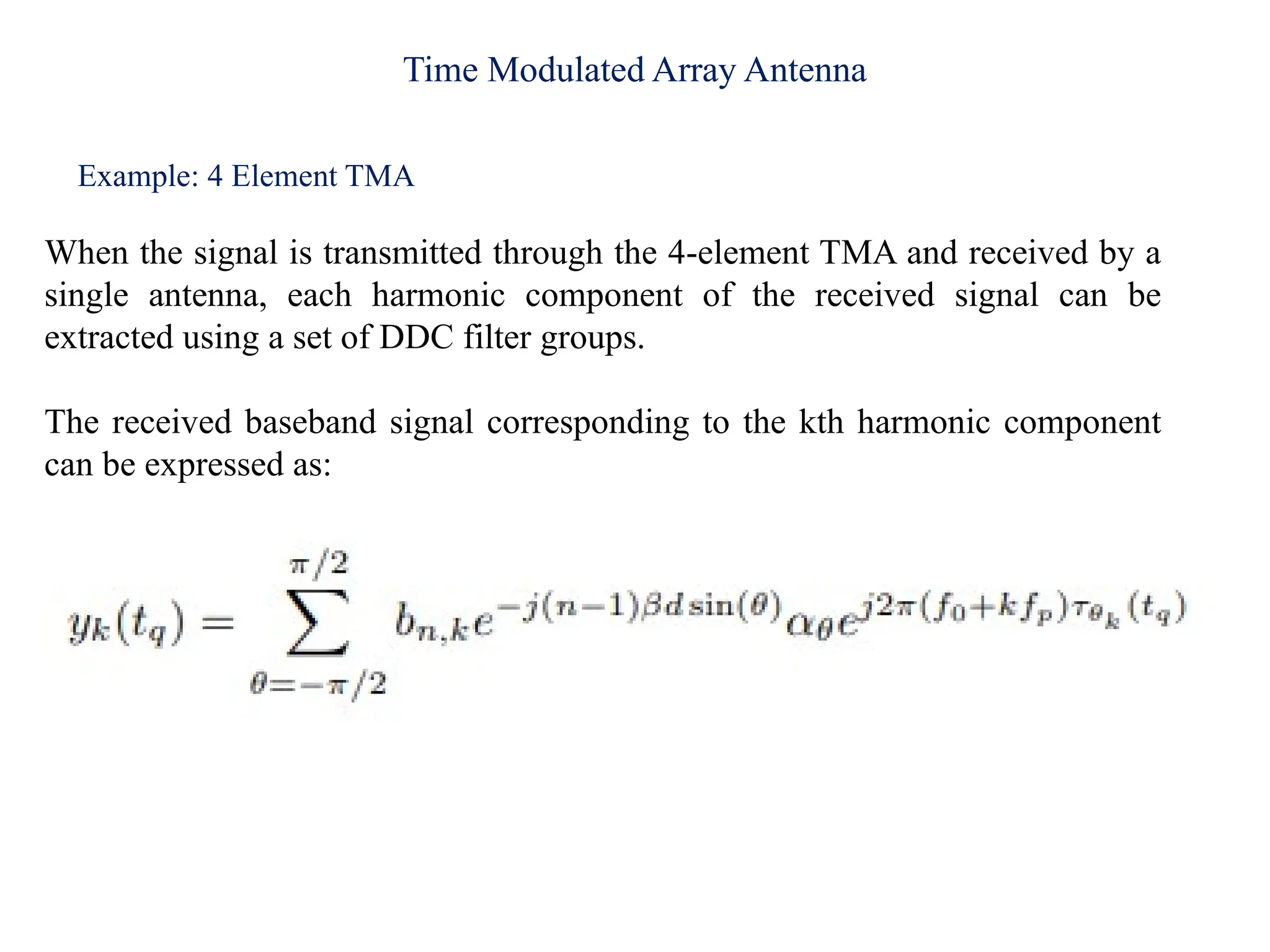
Example: 4 Element TMA
When the signal is transmitted through the 4-element TMA and received by a
single antenna, each harmonic component of the received signal can be
extracted using a set of DDC filter groups.
The received baseband signal corresponding to the kth harmonic component
can be expressed as:
10.
Noncontact Multi-person RespirationDetection Using
TMA
The TMA is employed to generate multiple harmonic beams, enabling the simultaneous
detection of human respiration from multiple directions.
Each harmonic component is extracted through a series of digital down-conversion (DDC)
operations applied to the received single-channel signal.
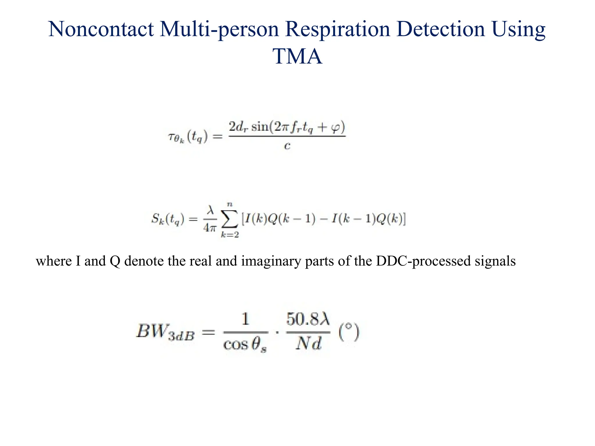
The respiratory signal of each individual is then obtained by analyzing the phase
information of the corresponding harmonic component.
A multi-person respiratory monitoring system was designed and implemented using a 2.4
GHz TMA continuous-wave radar prototype.
The system features a simple architecture and low computational complexity. In
experiments of single-person, two-person, and three-person scenarios, the maximum RR
estimation errors are 0.59, 0.98, and 1.30 bpm, respectively.
The proposed system can accurately detect the respiratory rates of three individuals
simultaneously and effectively identify abnormal breathing patterns among them,
demonstrating its capability to monitor health status in daily multi-person scenarios.
Noncontact Multi-person RespirationDetection Using
TMA
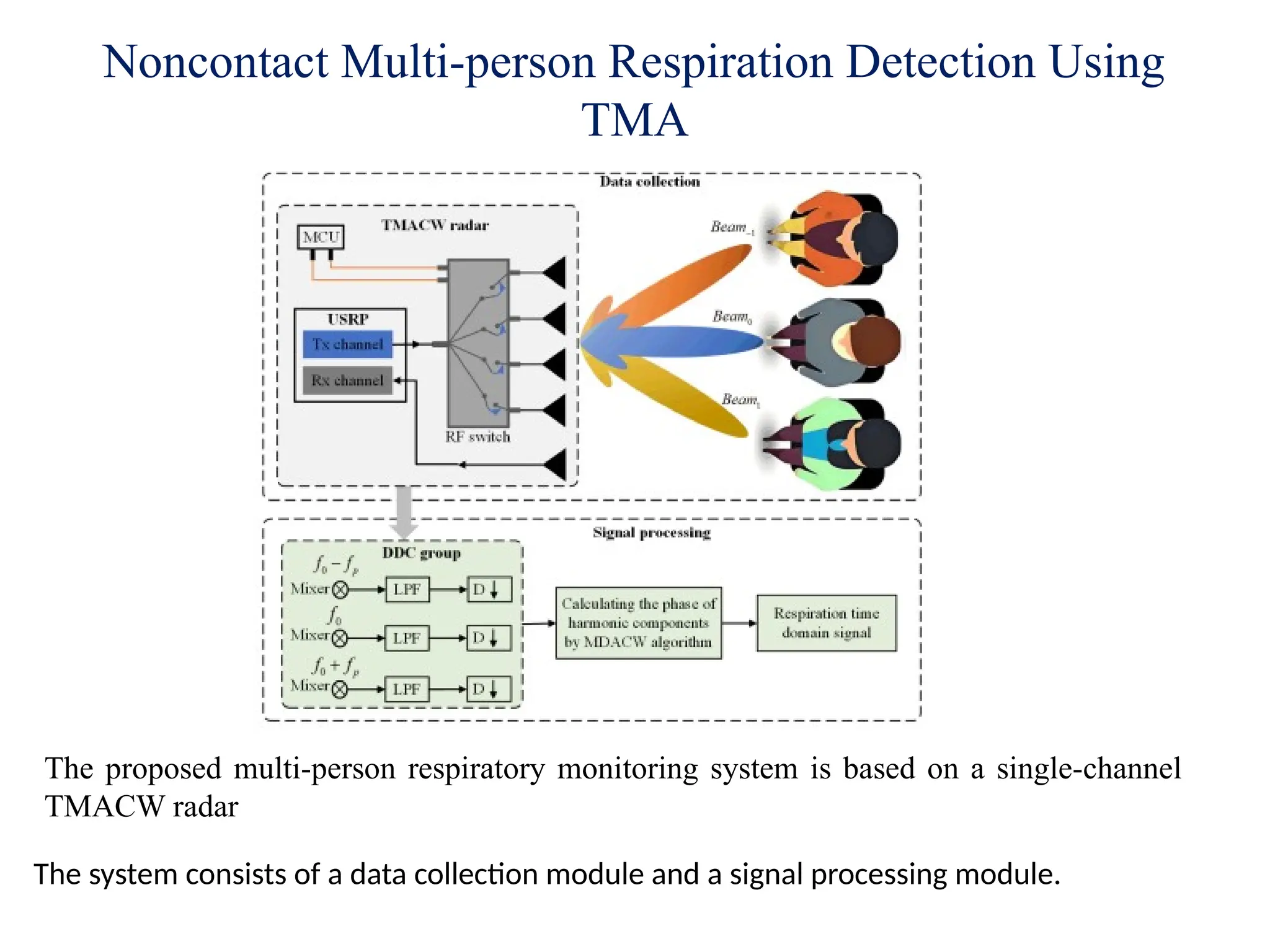
The proposed multi-person respiratory monitoring system is based on a single-channel
TMACW radar
The system consists of a data collection module and a signal processing module.
13.
Noncontact Multi-person RespirationDetection Using
TMA
In the data collection module, the TMACW radar is designed to capture echo signals from all
targets.
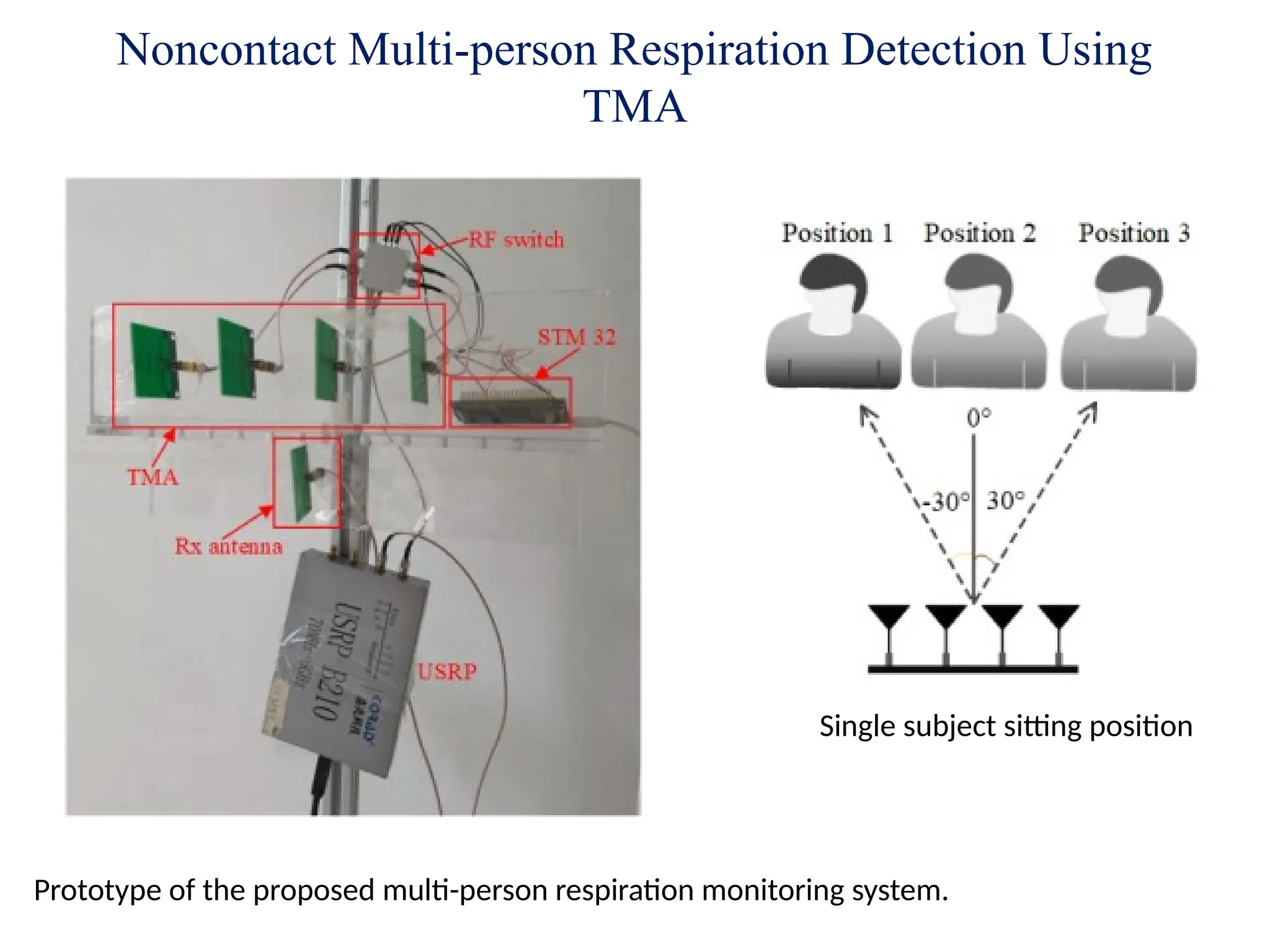
Specifically, a 4-element TMA is utilized, comprising four 2.4 GHz Yagi antennas with a
gain of 7 dBi, a single-pole four-throw RF switch, and an STM32F103C8T6 (STM32)
microcontroller unit (MCU).
The RF switch is periodically modulated by the STM32 MCU to sequentially activate each
array element.
The single-channel TMACW radar is implemented on a Universal Software Radio Peripheral
(USRP) B210 using the open-source GNU Radio framework.
The 4-element TMA is connected to the transmitting channel of the USRP B210 to generate
CW signals at 2.4 GHz.
A single receive antenna is connected to the receiving channel of the USRP B210 to capture
the echo signals.
The collected data is subsequently transmitted to a host computer via a USB connection for
further processing.
14.
Noncontact Multi-person RespirationDetection Using
TMA
In the signal processing module, a DDC filter group is introduced to extract the required
harmonic components.
Each DDC filter comprises a mixer, a low-pass filter (LPF), and a down sampling unit (D).
Initially, the received echo signals are mixed with the respective harmonic components,
thereby shifting their spectrum to the baseband.
The LPF is then applied to suppress interference from undesired harmonic components,
isolating the desired signals.
Down sampling is subsequently performed to reduce the data volume, thereby minimizing
both storage requirements and computational overhead during processing.
This process yields the fundamental component along with the harmonic components.
15.
Noncontact Multi-person RespirationDetection Using
TMA
Due to deviations between the modulation frequency generated by the STM32 and the
ideal modulation frequency, a frequency offset arises that affects harmonic component
extraction.
To mitigate this issue, frequency offset estimation and compensation are applied.
A linear regression algorithm is employed to estimate the phase slope of each harmonic
component, enabling the calculation and compensation of the frequency offset during the
mixing stage.
Specifically, 30- second data is first obtained in a static environment.
Based on the analysis shown in Fig, only the ±1st harmonic components and the
fundamental component are extracted in this work.
The accurate time-domain respiration signal is then obtained by computing the phase of the
harmonic components using the MDACM algorithm.
16.
Noncontact Multi-person RespirationDetection Using
TMA
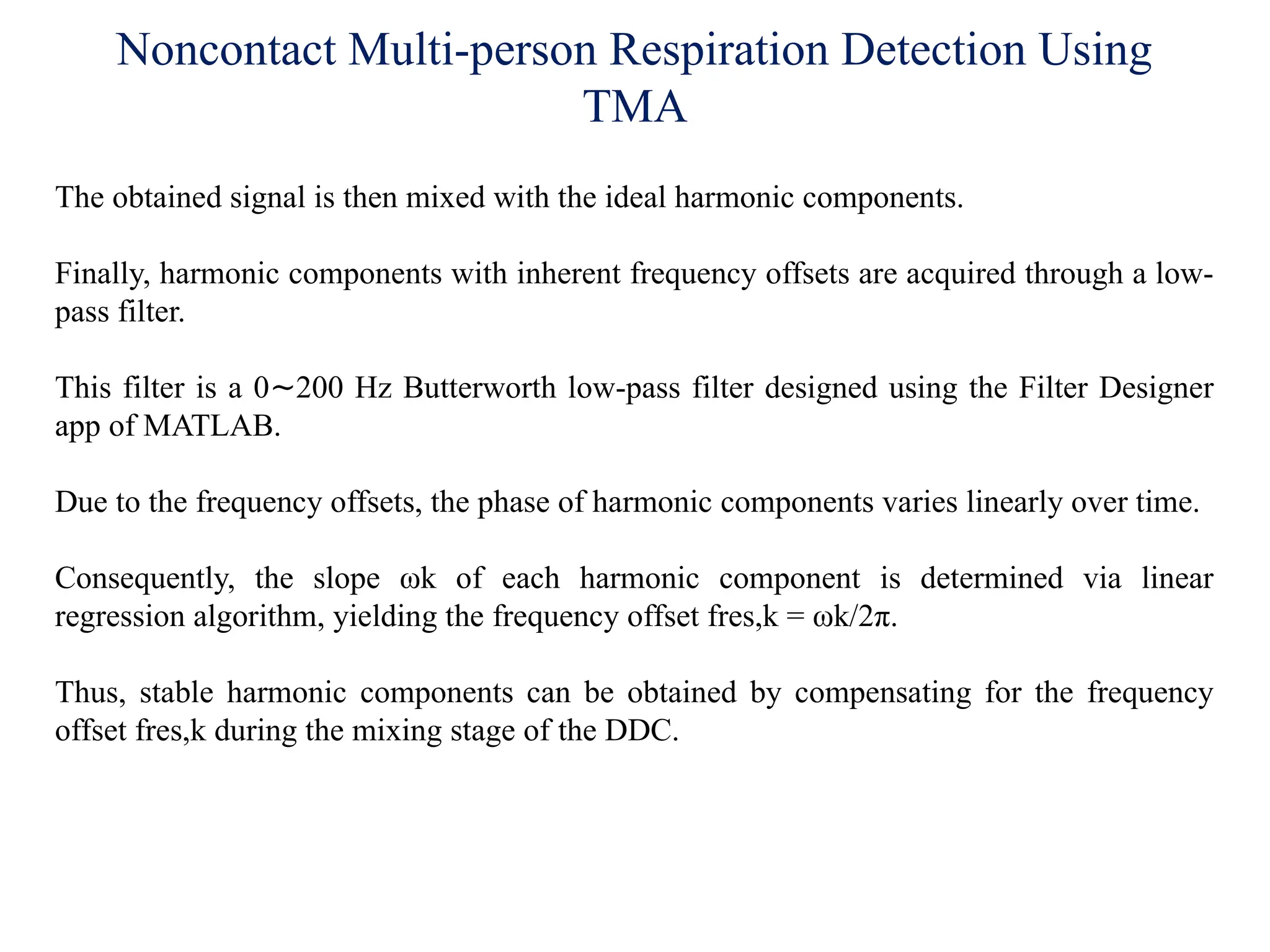
The obtained signal is then mixed with the ideal harmonic components.
Finally, harmonic components with inherent frequency offsets are acquired through a low-
pass filter.
This filter is a 0 200 Hz Butterworth low-pass filter designed using the Filter Designer
∼
app of MATLAB.
Due to the frequency offsets, the phase of harmonic components varies linearly over time.
Consequently, the slope ωk of each harmonic component is determined via linear
regression algorithm, yielding the frequency offset fres,k = ωk/2π.
Thus, stable harmonic components can be obtained by compensating for the frequency
offset fres,k during the mixing stage of the DDC.
17.
Noncontact Multi-person RespirationDetection Using
TMA
Prototype of the proposed multi-person respiration monitoring system.
Single subject sitting position
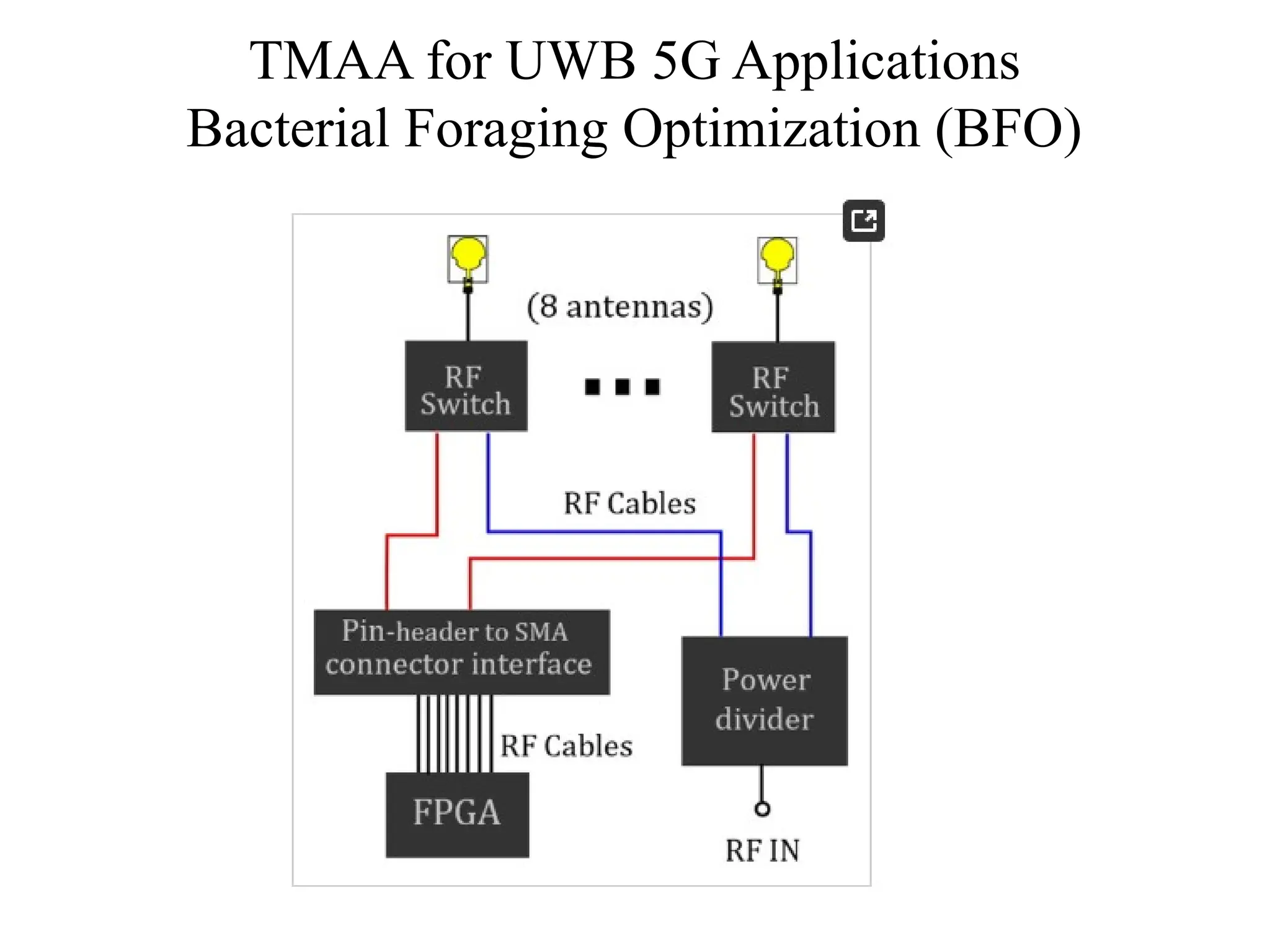
TMAA for UWB5G Applications
Bacterial Foraging Optimization (BFO)
The design problem is to discover the optimum locations denoted with xn and/or time
sequences tn for each element of the TMA to generate optimum radiation patterns in UWB.
In this scenario, the optimization variables are defined as:
The Q term is a matrix of optimization variables, and each element qi
represents
the xn and/or the time tn in which the antenna is turned on.
The index term i is an individual from the bacterial population.
During the optimization process, the element positions xn are searched by defining a
spacing (sn = xn − xn−1) among the antennas within the range of sn [λ, 2λ], where the
ϵ
wavelength λ is considering the lower band of fc = 3.1 GHz, i.e., sn [96.77 mm, 193.54
ϵ
mm].
This constraint is to avoid a possible overlapping and excessive mutual coupling among the
antennas. The time sequences are also constrained such as tn [0, 1]. The fitness function of
ϵ
this problem is computed as follows:
20.
TMAA for UWB5G Applications
Bacterial Foraging Optimization (BFO)

![TMAA for UWB 5G Applications
Bacterial Foraging Optimization (BFO)
The design problem is to discover the optimum locations denoted with xn and/or time
sequences tn for each element of the TMA to generate optimum radiation patterns in UWB.
In this scenario, the optimization variables are defined as:
The Q term is a matrix of optimization variables, and each element qi
represents
the xn and/or the time tn in which the antenna is turned on.
The index term i is an individual from the bacterial population.
During the optimization process, the element positions xn are searched by defining a
spacing (sn = xn − xn−1) among the antennas within the range of sn [λ, 2λ], where the
ϵ
wavelength λ is considering the lower band of fc = 3.1 GHz, i.e., sn [96.77 mm, 193.54
ϵ
mm].
This constraint is to avoid a possible overlapping and excessive mutual coupling among the
antennas. The time sequences are also constrained such as tn [0, 1]. The fitness function of
ϵ
this problem is computed as follows:](https://image.slidesharecdn.com/timemodulatedarrayantenna-250901165416-04588106/75/Time-Modulated-Array-Antenna-for-Synthesis-pptx-19-2048.jpg)