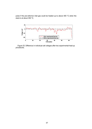
This document discusses improving the durability and reducing the complexity of solid oxide fuel cell (SOFC) systems. Specifically, it addresses:
1) Developing protective coatings for steel interconnects to limit chromium poisoning of the cathode and protect the steel from oxidation.
2) Investigating simplification of the fuel processing subsystem by recycling anode off-gas to eliminate the need for an external water source.
3) Developing durable sealing solutions for SOFC stacks to improve durability through limiting material interactions.
The overall goal is to increase SOFC durability and reduce system complexity and costs to enable market entry.


![4
Overall, the solution was found to be promising and the obtained results led to the
commercialisation of the developed seal solution by Flexitallic Ltd (UK) [1].
Keywords: Fuel cells, SOFC, chromium poisoning, anode off-gas recycling, sys-
tem heat-up, seal, interconnect, material interactions](https://image.slidesharecdn.com/a969d065-d741-4ce2-b38e-5ab0f6e7f2cd-160206144007/85/Thomann2015-dissertation-5-320.jpg)


![15
1. Introduction
1.1 Background and motivation
The development of a sustainable energy system is one of the global challenges
of our times. We need an energy system that fosters economic developments,
while having a sustainable footprint on the environment. Emissions of pollution
and resource consumption related to the energy sector have to be reduced to
acceptable levels. Moreover, the human impact on climate change has been es-
tablished [2] and significant efforts are being undertaken to curb greenhouse gas
(GHG) emissions [3].
Technological developments can contribute to addressing the different chal-
lenges of our energy system. Public electricity and heat production accounted for
27% of GHG emissions in Europe in 2012 [4]. Electricity generation is presently
dominated by fossil fuel-based generation, with about 50% of European electricity
coming from fossil fuels in 2010 [5]). This sector is undergoing deep transfor-
mations because of the pressure to reduce the carbon-footprint of electricity, coun-
tries phasing out nuclear electricity or reducing its share, and tighter emission
regulation on air pollution. Therefore, there is an important commercial potential
for technologies that can contribute to increasing the electricity production efficien-
cy and reducing its emissions in terms of pollution and GHG. Fuel cells are per-
ceived to have an important role to play in the power generation in stationary,
portable and transport applications due to their high electrical efficiency and very
low emissions [6,7].
Fuel cells are electrochemical energy conversion devices that convert chemical
energy from fuels directly into electricity and heat. Conversely to thermal power
generation, fuel cells do not involve a combustion process. Fuel cells are modular
in nature and can be scaled from a small generator (100 W) to an MW-class pow-
er plant, which makes them suitable for a wide range of applications. There are
different types of fuel cells based on their electrolyte material. The fuel cells oper-
ating at the highest temperature are called Solid Oxide Fuel Cells (SOFCs) and
operate between 600 and 900 °C. SOFCs have been the subject of intensive
research and development because of their specific advantages.
SOFCs can achieve high efficiency even in small power units, with a demon-
strated system electrical efficiency of 60% in units as small as 1–2 kW [8]. The](https://image.slidesharecdn.com/a969d065-d741-4ce2-b38e-5ab0f6e7f2cd-160206144007/85/Thomann2015-dissertation-16-320.jpg)
![16
high operating temperature of SOFCs means that they can provide high quality
heat for CHP applications. SOFCs have extremely low emissions. Because no
combustion is taking place, nitrogen oxide and particulate matter emissions are
insignificant. In addition, sulphur oxide emissions are extremely low because sul-
phur is a poison to SOFCs and is removed from the fuel feedstock before use.
SOFCs also emit considerably less noise than combustion engines. The high
temperature of operation of SOFCs enables a wide fuel flexibility and they can be
designed to operate on hydrocarbon fuels, the infrastructures of which are already
well developed. They are therefore a technology of choice for renewable fuels
such as biogas, landfill gas, syngas from biomass gasification, biofuels and fuels
produced from renewable electricity (power-to-gas route) [9-11] and thus they can
additionally contribute to the reduction of GHG emissions and resource depletion.
Despites its advantages, the road to market has proven to be challenging for
SOFCs. The main reasons hindering their market entry so far are their high cost,
which is partly due to their insufficient durability and high system complexity. How-
ever, it should be noted that the market for SOFCs has seen a marked improve-
ment in the last few years with 27 MW of shipped SOFC units worldwide in 2012
[12]. The market is presently driven by the demand for prime power for datacen-
tres in the USA and CHP units in Japan and Europe.
Cost and lifetime targets of SOFCs depend on the specific application. For ex-
ample, in their multi-annual implementation plan (2008–2013), the Fuel Cell and
Hydrogen Joint Undertaking (FCH JU) specifies the SOFC technical targets for
large commercial or industrial applications (300 kW – 5 MW) [13]. By 2015, the
targets are 20,000 h lifetime at 55% electrical efficiency at a system cost of 4000 €
kW-1
. By 2020, the targets are a lifetime of 40,000 h at 60% electrical efficiency
with a system cost of 2000 € kW-1
.
1.2 Scope of the dissertation
The capital cost of an SOFC system is seen as key challenges preventing their
market entry; it requires an improvement of their durability and a reduction of the
system complexity to drive the overall cost down. The dissertation focuses on a
selection of studies that address these challenges at the stack and system level.
One of these challenges is the prevention of cathode performance degradation.
Several degradation phenomena can affect the durability of the cathode such as
microstructural change, decomposition of the cathode material, chemical reaction
with the electrolyte material, spallation of the cathode and chromium poisoning
[14]. Despite numerous publications have been published on chromium poisoning,
this topic was selected because some questions are still unanswered. It is estab-
lished that volatile chromium species originating from stainless steel components
can deposit on the cathode and degrade their performance over time, leading to
insufficient SOFC lifetime. Most effort in research have targeted the development
of protective coatings for metallic interconnect, however, the data about the dura-](https://image.slidesharecdn.com/a969d065-d741-4ce2-b38e-5ab0f6e7f2cd-160206144007/85/Thomann2015-dissertation-17-320.jpg)
![21
The fuel cell efficiency, , is obtained by multiplying the efficiency components
(Equations 6 and 10) and the fuel utilisation (Equation 11):
= = (12)
which is the electric power produced in the cell divided by the chemical power of
the fuel flow.
In fuel cell systems, auxiliary devices, such as the blowers, cause parasitic
losses. In addition, the current cable and the direct to alternating current convertor
cause additional losses. If we assume that the auxiliary devices use grid electrici-
ty, the fuel cell system efficiency, , can be expressed as:
=
+ (13)
where is the power demand of auxiliary devices and corresponds to the
alternating current power supplied by the fuel cell to the grid after conversion to
alternating current.
Presently, the highest SOFC system efficiency reported in the literature is 60%
from natural gas (lower heating value) to net export of alternating current electricity
to the grid [8].
2.3 SOFC stack components
2.3.1 Electrolyte
The electrolyte needs to transport oxygen ions from the cathode to the anode, to
be electronically insulating and to be dense to avoid the mixing of the fuel and the
air atmosphere. It also needs to be stable in reducing and oxidising atmospheres
and chemically and physically compatible with the electrode materials. The mate-
rials of choice are dense ceramic and the most commonly used is yttria-stabilised
zirconia (YSZ) [15].
2.3.2 Anode
The anode needs to be catalytically active towards hydrogen oxidation, electrically
conductive to direct the electrons to the interconnect, ionically conductive and its
material should be stable in reducing conditions. Commonly, nickel is used in
combination with YSZ in a porous cermet (a composite material of metal and ce-
ramic). Nickel offers sufficient catalytic activity and is a good electrical conductor.
In addition, it is also catalytically active towards steam reforming of methane,
which is a significant advantage because it allows the use of methane as a fuel as
explained in more detail in Section 2.4. The YSZ phase allows the transport of](https://image.slidesharecdn.com/a969d065-d741-4ce2-b38e-5ab0f6e7f2cd-160206144007/85/Thomann2015-dissertation-22-320.jpg)
![22
oxygen ions towards the electrochemically active anode sites, at the triple-phase
boundary between the nickel, the YSZ and the hydrogen-rich atmosphere [15].
2.3.3 Cathode
The requirements for the cathode are to be active for oxygen reduction, transport
of the oxygen ions to the electrolyte and distribution of electric current associated
with the cathode reaction. Perovskite materials such as doped-lanthanum manga-
nite (La,Sr)MnO3 (LSM) have been extensively used as cathode material. Howev-
er, LSM is a largely electronic conductor, which restricts the reaction to the triple-
phase boundary with the YSZ material. In order to increase the cathode active
site, mixed ionic electronic conductor perovskites are also used as a cathode
material, such as (La,Sr)CoO3 (LSC) [16] and (La,Sr)(Co,Fe)O3 (LSCF) [17].
A major issue with SOFC cathodes is the so-called chromium poisoning. Chro-
mium evaporates from metallic interconnect and other steel balance-of-plant com-
ponents and is transported to the cathode, where it deposits and degrades the
cathode properties [18,19].
2.3.4 Interconnects
Interconnects have several functions in an SOFC stack. They collect electrons at
electrodes and transport them to the neighbouring cells. In addition, they separate
the fuel-rich atmosphere of the anode and the oxygen-rich atmosphere of the
cathode. The simultaneous exposure to reducing and oxidising atmospheres at
temperatures between 600 and 800 °C sets the high-temperature corrosion re-
sistance requirement very high. Lastly the interconnects ensure the homogenous
distribution of fuel and oxidants to the entire electrode surface [20-22].
The requirements of the interconnect materials are therefore:
i) High electrical conductivity
ii) High corrosion resistance
iii) Coefficient of thermal expansion matching with those of the other
components of the cell and stack
iv) Suitable mechanical properties at elevated temperature
v) Low cost materials and manufacturing method.
For SOFCs operating at temperatures as high as 1000 °C, ceramic interconnects,
such as doped-lanthanum chromite, are needed due to the challenging conditions
[20]. Thanks to progress in SOFC manufacturing, there has been a general trend
towards lowering the operating temperature of SOFCs to 600–800 °C, which al-
lows the use of stainless steel as interconnect materials. Compared to ceramic
interconnect material, stainless steels are generally more conductive, cheaper and
easier to manufacture and shape. The high electrical conductivity requirement
eliminates the alumina-forming stainless steels. The need for coefficient of thermal
expansion (CTE) matching with the YSZ (about 10 × 10 6
°C 1
from 25 to 1000 °C)](https://image.slidesharecdn.com/a969d065-d741-4ce2-b38e-5ab0f6e7f2cd-160206144007/85/Thomann2015-dissertation-23-320.jpg)
![23
eliminates the austenitic stainless steels due to their higher CTE. Therefore, most
of the research has focused on using ferritic stainless steels for interconnect appli-
cations [23]. Several commercial alloys were developed for this specific purpose,
such as Crofer 22 APU (ThyssenKrupp VDM), E-Brite (Allegheny Ludlum), ZMG
(Hitachi), or Sandvik Sanergy HT (Sandvik Materials Technology). They contain
between 20–25% of chromium to meet the CTE and corrosion resistance require-
ments [24]. In order to further decrease the interconnect material cost, general
purpose stainless steel alloys such as AISI 441 are being investigated in combina-
tion with corrosion protective coating [25-29].
2.3.5 Seals
The development of effective sealing solutions that address all the seal require-
ments is essential for improving the durability of SOFC stacks and reducing their
cost [30,31]. Seals need to exhibit a low leak rate to decrease fuel loss (fuel leak-
ing to air side and vice versa). Moreover, if the leak is localised, the air leaking to
the anode side can cause local reoxidation of the nickel of the anode and can
cause the cell to crack. Another issue with localised leakage is the formation of a
hot spot, a local increase in the temperature due to the exothermal reaction of fuel
and oxidant, which increases the degradation rate of the stack [32]. They need to
withstand simultaneous exposure to the air side and to the fuel side at tempera-
tures between 600 to 900 °C. Additionally, their performance should not be affect-
ed by hundreds to thousands of thermal cycles for stationary and mobile applica-
tions respectively. Moreover, they need to be chemically compatible with the adja-
cent components like the interconnects and cell materials over the lifetime of the
SOFC stack. The seal material should be electrically insulating to avoid short-
circuiting. Lastly, the seals should also be inexpensive, easy to assemble and
compensate for the manufacturing tolerances of the other stack components.
Currently, glass ceramic seals are widely used in SOFC stacks. Their wet adja-
cent surfaces form a very gas-tight structure (e.g. 0.01 ml (min m)-1
[33]) with few
interfacial leakages. However, their main drawback is that the glasses are fragile
and withstand tensile stress poorly, which makes them susceptible to failure when
thermo-mechanical stresses are present, especially during thermal cycling. Addi-
tionally, the properties of glass or glass-ceramics (such as the coefficient of ther-
mal expansion (CTE)), viscosity and porosity change over time, and these chang-
es can create additional thermo-mechanical stresses during long-term operation
and increase the risk of seal failure [31,34].
Compressive seals composed of mica-type paper have been investigated as an
alternative [32,35,36]. Because compressive seal material exhibits some deforma-
bility and the seals are not rigidly bonded to the adjacent surface, they are more
resistant to thermo-mechanical stresses. However, their leak rates are usually
higher and are dominated by the interfacial leak paths, especially at low compres-
sion stresses [37,38].](https://image.slidesharecdn.com/a969d065-d741-4ce2-b38e-5ab0f6e7f2cd-160206144007/85/Thomann2015-dissertation-24-320.jpg)
![24
2.4 Fuel processing for SOFC
SOFCs have a significant advantage over low-temperature fuel cells in the field of
fuel flexibility. Because they operate at high temperatures, i.e. 600–900 °C, me-
thane can be reformed on the nickel cermet anode, carbon monoxide does not
poison the anode catalyst, and recoverable heat is available for steam reforming
reaction [39-41]. Therefore, SOFCs can use a wide range of hydrocarbon fuels
from renewable or fossil sources with a relatively simple fuel processing subsys-
tem. They have been operated on biogas [42], natural gas [43], liquefied petrole-
um gas reformate [44], propane [45], methanol [46] and diesel reformate [47].
Hydrocarbon fuels are typically processed by steam reforming (SR) according
to equation 14, by catalytic partial oxidation (Equation 15) or by oxidative-steam
reforming, which uses a mixture of air and steam as a reforming agent. Steam
reforming is a very endothermic reaction with a change of enthalpy H°r of +206
kJ mol-1
for methane, while catalytic partial oxidation is exothermic with H°r = -38
kJ mol-1
for methane [48].
CnHm + n H2O n CO + (n + m/2) H2 (14)
CnHm + n/2 O2 n CO + m/2 H2 (15)
Natural gas is currently widely used as a fuel for SOFCs due to the availability of
its infrastructure and low requirements for fuel processing. Its exact composition
depends on its source but the main compounds are methane and light hydrocar-
bon like ethane and propane. A typical natural gas composition from the grids of
the United States, Australia, Denmark and Finland are listed in Table 1.
Table 1. Natural gas composition from various national grids.
Main components
Natural gas grid from CH4 C2H6 C3H8 CO2 N2
USA [49] 87–97 1.5–7 0.1–1.5 0.1–1 0.2–5.5
Australia [8] 91.0 5.0 0.5 2.4 1.0
Danmark [50] 89.1 6.0 2.4 1.0 0.3
Finland [51] 97.9 0.9 0.3 0.0 0.8
Typically, the natural gas is partially reformed before the stack in a pre-reformer.
On the one hand, it is beneficial to maintain some internal reforming inside the
stack because the endothermic steam reforming reaction cools down the stack,
which reduces the need for stack cooling with excess cathode air and the parasitic
loss associated with the air blower. On the other hand, a high degree of internal
reforming causes a large temperature gradient and thermal stress at the anode](https://image.slidesharecdn.com/a969d065-d741-4ce2-b38e-5ab0f6e7f2cd-160206144007/85/Thomann2015-dissertation-25-320.jpg)
![25
inlet and is detrimental to the durability of the stack [52]. Additionally, there is a
risk of carbon formation at the anode at high degrees of internal reforming and this
risk increases with higher hydrocarbon fraction [53,54]. In order to decrease the
degree of internal reforming, a natural gas-fuelled SOFC system typically includes
a pre-reformer upstream of the stack. In the pre-reformer, the fuel is converted to
syngas (methane, carbon monoxide and dioxide, hydrogen and steam). The de-
gree of conversion depends on the steam-to-carbon ratio and the pre-reformer
temperature.
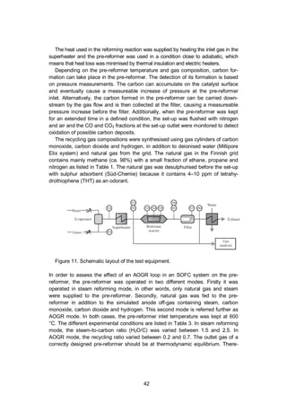
2.5 SOFC system layout: an example
The scope of this section is not to provide an exhaustive introduction to SOFC
systems, but rather to present a specific layout. This specific layout is relevant to
the present work because the experiments of Publications III and IV were de-
signed to produce results applicable to this system. The SOFC system is illustrat-
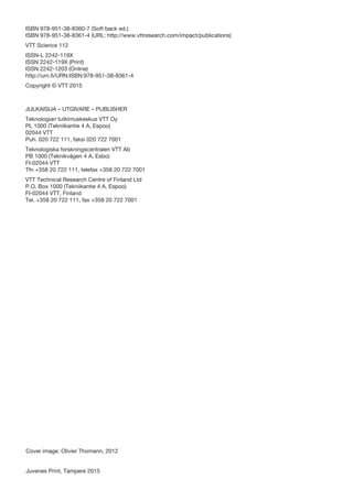
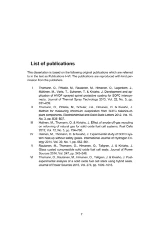
ed in Figure 2 and consists of the stack module and the BoP components module.
A detailed description of this system and its performance can be found in [43]. The
system uses an anode off-gas recycling (AOGR) loop, which enables operation
without an external water supply when sufficient steam is produced in the stack.
The natural gas is fed to the system and mixed with the recycled anode exhaust
gas before being heated up in the fuel heat exchanger. The fuel is then partially
reformed in the pre-reformer and fed to the stack. The stack fuel outlet gas is used
to heat up the inlet fuel and then a fraction of the fuel is recycled by the AOGR
blower. An important parameter is then the recycling ratio (RR), which corre-
sponds to the fraction of the flow of recycled gas over the total flow of anode off-
gas. The rest of the fuel exhaust gas is fed to a catalytic burner, where the unre-
acted fuel fraction is burned with the exhaust air. The heat produced in the catalyt-
ic burner is used to heat up the inlet air. The inlet air is fed to the system by an air
blower and heated up in the air heat exchanger before being fed to the stack.
Additionally, two by-pass valves are used to control the temperature of the stack
and the burner. In addition, two electric heaters are used during start-up, one
before the stack inlet inside the stack module and another one before the AOGR
blower. The system is designed to be thermally self-sustained during operation.](https://image.slidesharecdn.com/a969d065-d741-4ce2-b38e-5ab0f6e7f2cd-160206144007/85/Thomann2015-dissertation-26-320.jpg)
![26
Figure 2. VTT 10 kW demo unit layout with fuel system gas sampling locations.
Reproduced and adapted from Ref. [43]. Copyright 2011, The Electrochemical
Society.
As mentioned, not all the fuel is used in the stack and this is described by the
stack fuel utilisation parameter ( ) (Equation 11). As discussed in Section
2.2, it is beneficial to have high fuel utilisation for electrical efficiency. However,
there is an optimal value for the stack fuel utilisation because concentration volt-
age loss becomes important at high fuel utilisation. Moreover, if all the fuel is used
in the stack, the nickel of the anode starts to oxidise from the stack outlet, which is
highly detrimental to the cell integrity. In a system equipped with an AOGR loop,
part of the unused fuel is recycled, which means that the system fuel utilisation
( ) becomes higher than the stack utilisation. System fuel utilisation can be
calculated from the stack fuel utilisation with Equation 16 [55].
=
1 +
(16)
For example, the VTT 10 kW demo unit operates at about 80% system fuel utilisa-
tion, while the stack fuel utilisation is kept at about 60% in nominal conditions.
FUEL
AIR
START-UP
STEAM
Rin Ain Aout
heater
Anode
recycle
Air
blower Air
HEX
Burner
SOFC
stack
Fuel
HEX
Pre-reformer
heater
BOP MODULE STACK MODULE
HEAT RECOVERY & EXHAUST ELECRIC GRID
Power
conversionDC
AC](https://image.slidesharecdn.com/a969d065-d741-4ce2-b38e-5ab0f6e7f2cd-160206144007/85/Thomann2015-dissertation-27-320.jpg)
![27
3. Prevention of chromium poisoning
3.1 Protective coating for metallic interconnects (Publication I)
3.1.1 Background
Ferritic stainless steels are widely used as interconnect materials because they
offer an advantageous balance between the fulfilment of their different require-
ments such as good electrical conductivity, matching of CTE with cell materials
and the low cost associated with the material and manufacturing methods [56].
However, the thermally grown oxide layer is mainly composed of chromium oxide
and is a source of volatile chromium species, which have been found to deposit on
the cathode and cause the so-called chromium poisoning. Chromium poisoning
decreases the performance of the cathode over time, which reduce the durability
of SOFC [19,57,57-62]. Some ferritic stainless steel alloys were specifically de-
signed for SOFC operation such as Crofer 22 APU (ThyssenKrupp VDM), E-Brite
(Allegheny Ludlum, or ZMG (Hitachi) and they form an outer chromium-
manganese spinel layer with a lower area-specific resistance (ASR) and a lower
chromium evaporation rate (up to 75% reduction of evaporation rate) [58]. Howev-
er, the reduction of chromium evaporation brought about by optimised steel com-
position is seen as insufficient and a protective coating is necessary to further
reduce the chromium evaporation rate and thus improve the durability of SOFCs
[23].
In order to reduce chromium evaporation and oxidation of stainless steel, pro-
tective coatings need to have no porosity or closed porosity and low diffusivity of
oxygen and chromium through the coating. Moreover, the addition of a coating
should not decrease the performance of the SOFC and therefore a coating needs
to have a low and stable ASR and good chemical, physical and structural compat-
ibility with the adjacent components.
A wide range of protective coatings have been reported in the literature [23] and
among them (Mn, Co)3O4 has received attention for its good performance [63-66].
Numerous methods have been used to deposit such coatings like slurry spraying
[67,68], radio-frequency sputtering [68], magnetron sputtering [69,70], plasma
spraying [71], atomic layer deposition [72], pulsed laser deposition [73], electro-
deposition [74], and filtered arc [75]. In addition, MnCO2-xFexO4 spinel coating has
been tested for its better electrical conductivity [65,66].](https://image.slidesharecdn.com/a969d065-d741-4ce2-b38e-5ab0f6e7f2cd-160206144007/85/Thomann2015-dissertation-28-320.jpg)
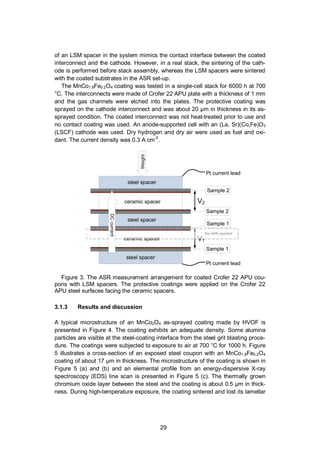
![28
The goal of the work reported in Publication I was to assess the performance of
MnCo2O4 and MnCo1.8Fe0.2O4 spinel coatings on Crofer 22 APU steel by high
velocity oxy-fuel (HVOF) spraying. Thermal spraying was chosen because it pro-
duces coatings that are already very dense and additional sintering is not neces-
sary because the coating is formed by molten or semi-molten droplets. Among
thermal spraying method, HVOF spraying was selected because it produces coat-
ing with a high tensile bond strength [76]. For this purpose, high-temperature oxi-
dation behaviour and ASR of the coated steel samples were investigated. Addi-
tionally, a post-experimental analysis was performed on a single-cell stack using a
coated interconnect that was operated for 6000 h. The post-experimental analysis
focussed on the evaluation of the coating microstructure, the oxidation of the inter-
connect, and the transport of chromium. To the authors’ knowledge, (Mn,Co)3O4
and MnCo2-xFexO4 spinel coatings deposited by HVOF spraying for SOFC inter-
connects have not been previously reported in scientific journals.
3.1.2 Experimental
Coated Crofer 22 APU test coupons were prepared to evaluate their high tempera-
ture oxidation behaviour and to measure their ASR over time. Commercial Crofer
22 APU steel (ThyssenKrupp VDM) with a thickness of 0.2 mm was used as a
substrate for test coupons. The coupons were coated by HVOF spraying with a
Praxair HV2000 spray gun fitted with a combustion chamber. Nitrogen was used
as powder carrier, hydrogen as fuel and air as oxidant.
The high-temperature behaviour was investigated in exposure tests with 10 x
10–15 x 0.2 mm coated coupons. The samples were coated on both sides and
only the edges were uncoated. The test was conducted in humidified air (3% vol.
steam) for 1000 h at 700 °C. Cross-sections were prepared from the sample for
scanning electron microscopy (SEM) observation.
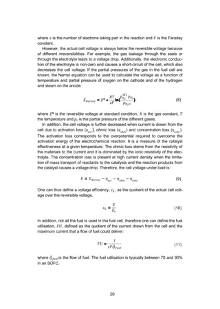
The ASR of the coated interconnect needs to be low and stable over time. For
this reason, the ASR was measured for 1000 h at 700 °C in a test arrangement
illustrated in Figure 3. The test samples consisted of two coatings (MnCo1.8Fe0.2O4
and MnCo2O4) deposited on two 26 x 26 x 0.2 mm steel coupons separated by a
ceramic spacer mimicking a cathode. In addition, an uncoated steel plate was
tested as a reference. Green La0.85Sr0.15Mn1.1O3 (LSM) spacers (20 x 20 x 1 mm,
IRD Fuel Cells A/S, Denmark) were used as separation material in order to serve
as a contact surface with a material similar to an SOFC cathode. Therefore, the
investigated contact resistance interface was coated steel against LSM. Several
samples were stacked up and a vertical load of 20 N was applied to the samples.
Steel plates of 1 mm thickness were used as separator disks between each sub-
strate-coating system. All samples were connected in a single direct current (DC)
loop with a current density of 0.2 A cm-2
. The samples were slowly heated up in
flowing air to burn off the binder from the green LSM spacers, until 850 °C. The
samples were held at 850 °C for 12 hours to sinter the LSM spacer. The steady-
state measurements were conducted at 700 °C in dry air. The ASR reported cor-
responds to half of the ASR measured for one substrate-coating system. The use](https://image.slidesharecdn.com/a969d065-d741-4ce2-b38e-5ab0f6e7f2cd-160206144007/85/Thomann2015-dissertation-29-320.jpg)
![32
line with results obtained for MnCo2O4 spinel coatings deposited by a slurry-
coating technique [77] or using a similar test arrangement including cathode mate-
rial spacers [68,78].
The ASR of the uncoated Crofer 22 APU in contact with the LSM spacer was
initially about 100 m cm2
and decreased during the tested period to reach 45
cm2
after 1000 h. The observed decrease in ASR over time is attributed to the
formation of a conductive (Cr, Mn)3O4 spinel layer on top of the oxide layer, which
improves the electrical contact between steel and LSM. This behaviour was previ-
ously observed by Yang et al. [68,79]. In principle, the observed decrease in ASR
could also be attributed to possible sintering of the green LSM spacer and conse-
quent increasing of its bulk conductivity, however this initial improvement was not
observed for the coated samples that were also using green LSM spacers. The
ASR of both coated samples was initially smaller than the uncoated Crofer 22
APU, which is counterintuitive because the coating is expected to have some
resistance. Therefore, it is believed that the initial difference originates from a
lower contact resistance of the coated samples.
Figure 6. Measured ASR in a 4-point DC measurement of Crofer 22 APU cou-
pons, coated and uncoated, all in contact with an LSM spacer. The coatings are
MnCo1.8Fe0.2O4 and MnCo2O4.
Finally, a post-experimental analysis was performed on a single-cell stack that
used a coated interconnect. The aim of the post-experimental analysis was to
assess the performance of the coating in terms of interconnect oxidation and re-
tention of chromium. Four back-scattered electron (BSE) SEM cross-sections of
the single-cell stack are illustrated in Figure 7. Figure 7 (a) presents a low-
magnification view of the cathode side where the air channel and the contact loca-
tion between the cathode and the coated interconnect are visible. The coating](https://image.slidesharecdn.com/a969d065-d741-4ce2-b38e-5ab0f6e7f2cd-160206144007/85/Thomann2015-dissertation-33-320.jpg)
![33
covers the interconnect completely, including geometrically challenging features
like the edges of the interconnect ribs.
Figure 7 (b) shows the contact location between the cathode and the intercon-
nect coated with MnCo1.8Fe0.2O4. The chromium oxide scale is about 1 µm in
thickness after 6000 h at 700 °C in air. Figure 7 (c) shows the coated interconnect
at an air channel location. The chromium oxide scale below the coating is also
about 1 µm in thickness. These results can be compared with the exposure tests
presented above where the chromium oxide layer of the coated steel was about
0.5 µm in thickness and the oxide layer of the uncoated steel was about 2.5–3 µm
after 1000 h in air at 700 °C. Therefore, the coating solution appears to effectively
reduce the oxidation of the interconnect in a long-term test in an SOFC environ-
ment. The elemental composition of the coatings at both locations was analysed
by EDS but no chromium could be detected (detection limit is about 0.3%-at),
which indicates that the diffusion of chromium is effectively hindered by the coat-
ing. The chromium content of the cathode was also investigated and no chromium
could be detected in the cathode at the interconnect contact location (Figure 7
(b)). Figure 7 (d) illustrates the cathode at an air channel location and an EDS
chromium concentration profile across the cathode. The EDS analysis reveals that
chromium was present in the cathode at this air channel location. Chromium dis-
tribution is inhomogeneous and peaks at 2.1%-at. The chromium source for this
contamination can either be the stainless steel interconnect, coming through the
protective coating, or the uncoated Crofer 22 APU air manifold and Inconel 600 air
inlet pipe upstream of the stack. However, chromium contamination was only
found at the air channel location (Figure 7 (d)) and not at the contact location with
the interconnect (Figure 7 (b)), which supports the hypothesis that the chromium
has originated from the uncoated air manifold and inlet pipe. Additionally, the EDS
analysis showed that no chromium could be detected in the coating, suggesting
that negligible chromium diffusion appears to take place across the coating. Stain-
less steel components and manifold upstream of the cells have been previously
identified as chromium contamination sources [80] and the work presented in
Publication II also shows that BoP components can be a significant source of
volatile chromium [81].](https://image.slidesharecdn.com/a969d065-d741-4ce2-b38e-5ab0f6e7f2cd-160206144007/85/Thomann2015-dissertation-34-320.jpg)
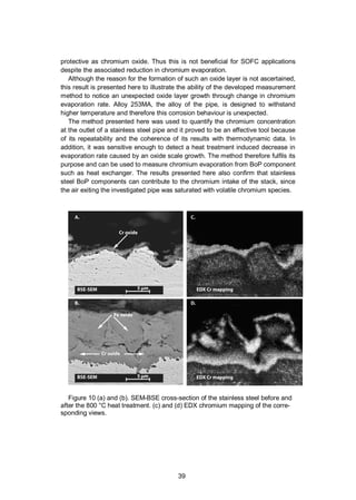
![34
Figure 7. SEM-BSE cross-section from the single-cell stack at different loca-
tions. (a) Low-magnification image of the air side of the single-cell stack. The
interconnect coating composition is MnCo1.8Fe0.2O4. (b) The contact area between
coated interconnect and cathode. (c) Surface of the interconnect at an air channel
location. (d) Cathode with an EDS chromium profile.
3.2 Method for measuring chromium evaporation
(Publication II)
3.2.1 Background
As discussed in Section 3.1, chromium poisoning of cathode is seen as one of the
major issues with respect to the durability of SOFCs. A large amount of literature
has been dedicated to the development of solutions to reduce the transport of
chromium from stainless steel interconnect materials to the cathode. Section 3.1
presented such a solution in the form of a protective coating applied by HVOF
spraying. However, metallic interconnects are not the only possible source of
chromium in an SOFC system. Commonly, the high-temperature BoP compo-
nents, such as piping and heat exchangers, are made of austenitic stainless steels
for their better mechanical and corrosion properties and are thus also a potential
source of volatile chromium species [58]. The chromium volatile species can then
be transported from the BoP component upstream of the stack to deposit on the
cathode as proposed in [82,83]. Due to the relative complex geometry of BoP](https://image.slidesharecdn.com/a969d065-d741-4ce2-b38e-5ab0f6e7f2cd-160206144007/85/Thomann2015-dissertation-35-320.jpg)
![35
components, most of the coating techniques developed for interconnects are not
applicable to BoP components. An assessment of chromium evaporation rates
from BoP components is therefore seen as a prerequisite for the development of
solutions to reduce this effect and the evaluation of improvements brought about
by such solutions. These include material selection [84], surface treatment such as
aluminising [85,86], coatings or chromium trapping [87]. Publication II aims to
contribute to this challenge by presenting a dedicated measurement technique.
Several methods to quantify chromium evaporation have been reported in the
literature and were reviewed in [88]. They all rely on the evaluation of small metal
coupons [58,89,90]. These methods are well adapted to comparing different sam-
ples. However, it is difficult to calculate from their results the actual amount of
chromium coming from a real complex-shaped component (uneven temperature
and flow profile and large surface area), as the evaporation rate depends on sev-
eral factors like the flow rate, flow regime and local temperature. This work focus-
es on the development of a method for measuring chromium evaporation directly
from the hot gas stream of a BoP component. The chromium collection is carried
out by using a coated denuder tube, a technique previously used by Froitzheim et
al. [89].
3.2.2 Experimental
The schematic drawing of the experimental set-up is illustrated in Figure 8. An
austenitic stainless steel pipe was evaluated as a simple BoP component. Howev-
er, the method could be used on a more complex component, e.g. a heat ex-
changer. The 1.2 m long pipe was of grade 253MA (Sandvik) and its composition
is given in Table 2. It was exposed to a high temperature in a furnace. Humidified
air (1.8 vol-% humidity) was fed into the pipe at a rate of 10 lN min-1
. A quartz de-
nuder tube (inner diameter 5.2 mm and length 500 mm) was inserted into the steel
pipe near its end. A fraction of the flow (from 15 to 35% of the main flow) was
sampled through this denuder tube by a diaphragm pump and a rotameter. The
inner wall of the denuder tube was dip-coated with sodium carbonate from a sur-
factant-containing solution. In the presence of humidity, the dominant species in
air is chromium oxyhydroxide which is formed according to equation (17) [91].
Cr2O3(s) + 2 H2O(g) + 3/2 O2(g) 2 CrO2(OH)2(g) (17)
The chromium oxyhydroxide reacts with the sodium carbonate coating according
to the equation (18). According to HSC [92], the equilibrium constant of this reac-
tion is above 1010
from room temperature to 800 °C.
CrO2(OH)2(g) + Na2CO3(s) Na2CrO4(s) + H2O(g) + CO2(g) (18)
Each measurement lasted 24 hours, after which the coated denuder tube was
replaced without cooling down the furnace, which is very time-efficient to perform](https://image.slidesharecdn.com/a969d065-d741-4ce2-b38e-5ab0f6e7f2cd-160206144007/85/Thomann2015-dissertation-36-320.jpg)
![36
repeated experiments. The chromium-containing coating was dissolved in 10%
nitric acid, diluted to obtain a suitable chromium concentration for inductively cou-
pled plasma mass spectrometry (ICP-MS, Thermo Scientific ELEMENT 2). The
effect of temperature of the stainless steel pipe on the chromium evaporation rate
was investigated by triplicated measurements that were carried out at 650, 700
and 750 °C.
Figure 8. Schematic drawing of the experimental set-up.
The effect of the heat treatment history of the stainless steel pipe was investigated
by measuring the chromium evaporation rate at 750 °C before and after a heat
treatment at 800 °C for 100 hours. SEM and EDS were used to investigate the
correlation between the change of evaporation rates and microstructure of stain-
less steel oxide layers.
Table 2. Nominal chemical composition of 253MA in %-weight [93].
C Si Mn P S Cr Ni N Ce
0.08 1.6 0.8 0.04 0.03 21 11 0.17 0.05](https://image.slidesharecdn.com/a969d065-d741-4ce2-b38e-5ab0f6e7f2cd-160206144007/85/Thomann2015-dissertation-37-320.jpg)
![37
3.2.3 Results and discussion
3.2.3.1 Measurement uncertainty
It was verified that the coated denuder tube was sufficiently long for chromium
collection by assessing that most of the chromium collected (70.7 +/- 17.2%) re-
acted in the first third of the tube. Actually only 7.3 +/- 1.8% of the total amount of
chromium collected reacted in the last third of the tube. Sodium carbonate coated
denuder tube can reach very high collection efficiency, for example, Froitzheim et
al. used a similar set-up to measure chromium evaporation from steel coupons
and they demonstrated a collection efficiency of 95% [89].
Measurement error on the chromium concentration in air was calculated to be
6% based on the errors of the individual measurement devices (flow meter, timer,
volume measurement, pipette, collection efficiency). The random error was 13%,
which corresponds to two times the standard deviation to have a confidence level
of 95% assuming a normal distribution of the measurement values. Therefore, the
overall uncertainty is thus 14%.
3.2.3.2 Effect of temperature on chromium evaporation
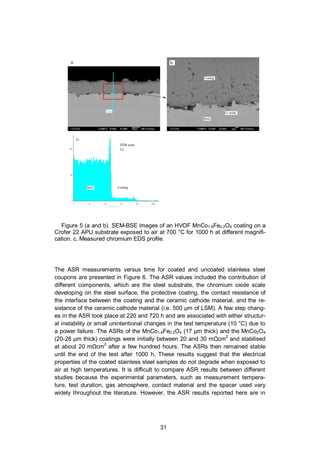
The Figure 9 illustrates the results from chromium evaporation measurements at
650, 700 and 750 °C in triplicates. The measured values are compared to value
calculated from thermodynamic data, assuming that the equilibrium pressure is
reached in the pipe. The three thermodynamics datasets are generated from three
different experimental studies and they were obtained from Stanislowski et al. [58].
The experimental results of chromium evaporation obtained with the method pre-
sented here are coherent with the thermodynamic data found in the literature. In
addition, the good repeatability of the method is demonstrated by the low standard
deviation.](https://image.slidesharecdn.com/a969d065-d741-4ce2-b38e-5ab0f6e7f2cd-160206144007/85/Thomann2015-dissertation-38-320.jpg)
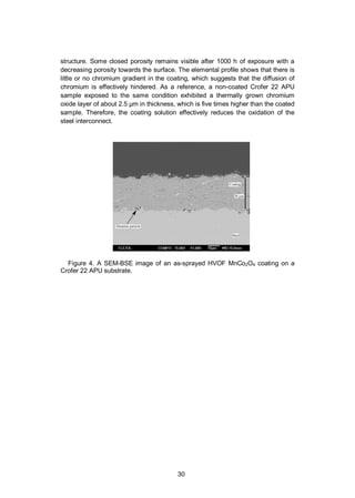
![38
Figure 9. Measured amounts and standard deviations of evaporated Chromium
at different temperatures. The experimental data are compared with calculations
based on thermodynamics data from different sources (data extracted from [58]).
3.2.3.3 Effect of heat treatment history on chromium evaporation
It was found that the temperature history has a significant effect on the amount of
chromium evaporation at 750 °C. A heat treatment of the pipe for 100 h at 800 °C
resulted in a reduction by a factor of four in the volatile chromium concentration in
the air exiting the pipe at 750 °C (from 8.0x10⁻⁸
to 2.0x10⁻⁸
kg m-3
). To investigate
the reason behind the decrease in chromium evaporation, the oxide layer on top of
the stainless steel was investigated by SEM cross-section and EDS elemental
mapping before and after the heat treatment. For this purpose, one pipe was ex-
posed at 750 °C for about 300 h. Another pipe was exposed in a same way, ex-
cept that it was subsequently exposed to 800 °C for 100 h before repeating the
chromium evaporation measurements at 750 °C.
Figure 10 (a) and (b) present SEM micrographs of cross-sections of the inner
surface of the stainless steel pipe before and after the exposure at 800 °C. Before
exposure at 800 °C, a thin oxide layer of about 1 µm is present on the steel sur-
face (Figure 10 (a)) and the oxide layer is chromium-rich (Figure 10 (c)). After
exposure at 800 °C, the oxide layer was found to be about 10 µm thick (Figure 10
(b)) and its oxide layer is not homogenous in composition. The inner layer is
chromium-rich and the top layer is depleted in chromium (Figure 10 (d)), but rich in
iron oxide.
The reduction of chromium evaporation is explained by a thicker oxide layer,
which is depleted from chromium at its surface. Enrichment in iron of the stainless
steel oxide layer is associated with high oxidation rate because iron oxide is not as](https://image.slidesharecdn.com/a969d065-d741-4ce2-b38e-5ab0f6e7f2cd-160206144007/85/Thomann2015-dissertation-39-320.jpg)
![40
4. Fuel processing subsystem
4.1 Effect of Anode off-gas Recycling on the pre-reformer
(Publication III)
4.1.1 Background
The present chapter presents a study (Publication III) aiming at implementing an
anode off-gas recycling loop in an SOFC system. An SOFC system that operates
on steam-reformed fuel relies on a continuous supply of steam. It is technically
simple to provide the steam from an external water supply with a deionisation
system and an evaporator. However, this approach has significant drawbacks: the
water source, the deionisation system and evaporator increase the system com-
plexity and its maintenance requirements. Alternatively, the steam produced by
the electrochemical reaction on the anode side (Equation 1) can be recycled back
to the fuel inlet. It can be realised by recycling a fraction of the SOFC anode off-
gas back to the fuel inlet. Thus, the need for an external water source is made
unnecessary at least during operation [94]. Another significant advantage of recy-
cling the anode off-gas is to increase the system efficiency. Because not all the
fuel is utilised when it passes through the SOFC stack, recycling a part of this
unreacted fuel allows to decrease accordingly the fuel inlet feed, which can im-
prove the electrical efficiency of the system [95,96]. Lastly, the stack fuel utilisation
can be decreased when an AOGR loop is used, which has been shown to be
beneficial for the stack durability [97].
In practise, the implementation of a hot AOGR loop (i.e. without steam conden-
sation) has proven challenging. AOGR can be implemented by a recycling blower
or by an ejector, but suitable components cannot be found off-the-shelf at the
moment [95]. Another issue is the risk of carbon formation which can occur if not
enough steam is recycled, i.e. if the recycling ratio is too low [98]. Moreover, the
risk of carbon formation increases when higher hydrocarbons than methane are
present in the fuel [54]. It is possible to predict the gas composition, temperature
and possibility for carbon formation using thermodynamic equilibrium calculation.
However, actual carbon formation eventually depends on the activity of the reform-
ing catalyst. Therefore, experimental investigation of the catalyst and pre-reformer
is needed to map the safe operating region without carbon formation. Lastly, there
is little experimental data reported in the literature on the effect of AOGR on cata-](https://image.slidesharecdn.com/a969d065-d741-4ce2-b38e-5ab0f6e7f2cd-160206144007/85/Thomann2015-dissertation-41-320.jpg)
![41
lyst activity. Peters et al. reported that AOGR caused a decrease of the activity of
a nickel-based catalyst [99], conversely Nummela et al. reported that AOGR had
no negative effect on the performance of another pre-reformer nickel catalyst
[100].
As already mentioned, the recycling ratio should be sufficient to have carbon-
free operation. However, it should not be too high either, because it means larger
parasitic electrical loss associated with the AOGR blower. In addition, AOGR
results in a dilution of the fuel at the anode, which decreases the cell voltage [96].
Therefore, the recycling ratio should be optimised to have carbon-free operation
and minimise the parasitic loss and the voltage drop.
This study aimed at generating the necessary results to build a pre-reformer for
a 10 kW SOFC system including an AOGR loop [43]. This work contributes to the
field of fuel processing in SOFC system by assessing experimentally the effect of
AOGR on the performance of a precious metal-based pre-reformer using natural
gas as a fuel. The performance of the pre-reformer in AOGR conditions is com-
pared against SR conditions. Additionally, the effect of varying the recycling ratio
is evaluated to determine its effect on the performance and to identify the mini-
mum recycling ratio that can be used safely in an SOFC system, i.e. correspond-
ing to carbon formation-free operation. The effect of the degree of reforming in the
pre-reformer on the thermal management of the stack is out of the scope of this
work. The temperature of the stack can be manage either by adjusting the degree
of reforming of the pre-reformer or by adjusting the air flow and its temperature to
the cathode. Results of this work led to the successful implementation of an anode
off-gas recycling loop in a 10 kW SOFC demonstration unit, where the system is
operated at nominal conditions without external water supply [43].
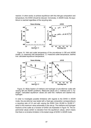
4.1.2 Experimental
The effect of AOGR on a precious metal catalyst-based pre-reformer was investi-
gated in a natural gas pre-reformer test bench. As illustrated in Figure 11, the test
bench consisted of the gas and deionised water mass flow controllers (EL-FLOW
and LIQUI-FLOW, Bronkhorst), a water evaporator and mixer (CEM-303, Bronk-
horst), a superheater (in-house built), a pre-reformer containing a commercially
available precious metal catalyst monolith (Süd-Chemie), micro-quartz particle
filters (MK 360, Munktell, designed to collect particles above 0.3 µm of diameter)
and a heat exchanger (Alpha-Laval) to condensate the water from the exhaust
gas. The temperature of the process gas was measured after the evaporator (TI1
in Figure 11), at the reactor inlet (TI2), at the catalyst monolith leading surface
(TI3), at the centre of the monolith (TI4), at the trailing edge of the monolith (TI5),
at the pre-reformer outlet (TI6), and after the filter (TI7). The process gas pressure
was measured before the evaporator (PI1), at the pre-reformer inlet (PI2) and
outlet (PI3) and after the filter (PI4). The dried pre-reformer exhaust gas was ana-
lysed by an online gas analyser (Sick S710 series) and with gas chromatographs
(Agilent 6890 N, Agilent 6850 and HP 5890 Series II).](https://image.slidesharecdn.com/a969d065-d741-4ce2-b38e-5ab0f6e7f2cd-160206144007/85/Thomann2015-dissertation-42-320.jpg)
![43
fore, the measured outlet gas temperatures and compositions are compared to the
calculated equilibrium values to assess the performance of the pre-reformer.
The gas compositions given in Table 3 have been calculated on the basis of
equilibrated gas with an in-house developed code [96]. Because this study aimed
to generate the necessary results to build a pre-reformer for a defined SOFC sys-
tem [43], the boundary conditions were predefined. In the calculations, the stack
outlet temperature (700 °C), the stack fuel utilisation (0.6) and the current density
were kept constant. Based on the heat exchanger layout (see Figure 2), the pre-
reformer inlet temperature was expected to be about 600 °C in nominal conditions.
An important parameter for the pre-reformer operation is the gas hourly space
velocity (GHSV), which is calculated by dividing the gas volume flow (Nm3
h-1
) at
normal temperature and pressure (NTP) by the catalyst volume (m3
). On the one
hand, it is advantageous to operate the pre-reformer at as high a GHSV as possi-
ble, since it minimises the pre-reformer size, the amount of expensive catalyst
material and the pressure drop at the pre-reformer. On the other hand, the GHSV
should be limited to a value at which the gas reaches thermodynamic equilibrium
at the pre-reformer outlet. A GHSV value of about 20,000 h-1
at recycling ratio of
0.5 was selected as a reference condition in this study. The GHSV was chosen
based on previous experience with this catalyst and the recycling ratio is based on
the results of an electrical efficiency optimisation study. The GHSV corresponding
to the different experimental conditions is plotted as a function of the recycling
ratio in Figure 12 (left). It can be noted that the GHSV increases with the recycling
ratio, which means that the residence time of the gas in the pre-reformer becomes
shorter. Additionally, the natural gas inlet flow rate is also plotted as a function of
the recycling ratio in Figure 12 (right) and it can be seen that the natural gas flow
rate decreases when the recycling ratio is increased, illustrating how much fuel
can be saved by increasing the recycling ratio.](https://image.slidesharecdn.com/a969d065-d741-4ce2-b38e-5ab0f6e7f2cd-160206144007/85/Thomann2015-dissertation-44-320.jpg)
![44
Table 3. Experimental conditions in SR and AOGR modes.
H2O/C
Recycling
ratio
GHSV
(h-1
)
NG CO CO2 H2 H2O
Methane
conversion
(%)
SR
2.5 – 21 900 28.6 0 0 0 71.4 17
2 – 18 800 33.3 0 0 0 66.7 15
1.5 – 15 700 40 0 0 0 60 13
AOGR
0.2 10 200 56.7 5.5 8.8 14.1 14.8 5
0.28 12 100 46 6.4 11.6 16.5 19.5 5
0.36 14 500 37.1 6.9 14 17.9 24 6
0.4 15 800 33.3 6.8 15.3 18.1 26.4 7
0.5 20 000 25 6.7 18.3 17.9 32.2 9
0.55 22 700 21.5 6.4 19.8 17.4 35 11
0.6 26 100 18.2 6 21.2 16.5 38 13
0.65 30 300 15.3 5.5 22.7 15.4 41.1 16
0.7 35 800 12.5 5 24.1 14.1 44.3 19
Figure 12. GHSV of the pre-reformer catalyst and the inlet natural gas flow rate
in SR ( ) and AOGR ( ) modes for different recycling ratio values.
The temperature limits of carbon formation in AOGR mode were calculated using
HSC6.1 [92] software to assess which experimental conditions could potentially](https://image.slidesharecdn.com/a969d065-d741-4ce2-b38e-5ab0f6e7f2cd-160206144007/85/Thomann2015-dissertation-45-320.jpg)
![45
lead to carbon formation in the pre-reformer. The equilibrium temperature and
composition of the pre-reformer outlet gas were calculated with the Cantera
toolbox [101] using GRI-Mech 3.0 reactions developed for natural gas combustion
[102]. The equilibrium was solved for an adiabatic system, where the total enthal-
py and pressure between reactants and products was kept constant.
In addition to short-term experiments, the pre-reformer was held in selected
conditions for a longer period to observe possible carbon formation or degradation
of the catalyst performance. The conditions of the different holds are detailed in
Table 4 and the longest hold was 1000 h.
Table 4. Operation conditions during extended holds.
Hold no. Recycling ratio (-)
Inlet temperature
(°C)
GHSV
(h-1
)
Hold time
(h)
1 0.6 609 26,100 122
2 0.5 597 20,000 121
3 0.5 598 20,000 117
4 0.5 513 20,000 67
5 0.5 600 20,000 1000
6 0.2 589 10,200 165
7 0.2 646 20,300 165
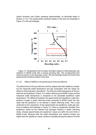
4.1.3 Results and discussion
4.1.3.1 Risk of carbon formation at thermodynamic equilibrium
In order to evaluate the effect of AOGR on the performance of a precious metal-
based catalyst, a pre-reformer was operated with simulated conditions relevant to
an SOFC system using steam-reformed natural gas, with or without an AOGR
loop. First of all, the risk of carbon formation was investigated and the carbon
formation limits based on thermodynamic calculations are illustrated in Figure 13.
According to thermodynamic equilibrium, the risk of carbon formation is more
severe at a lower recycling ratio. This stems from the O/C value (also showin in
Figure 13) which decreases with the recycling ratio, in other words, when less
steam and other oxygen-containing species from the anode outlet are recycled
back to the pre-reformer inlet. At a recycling ratio of 0.5, the calculated tempera-
ture limit of carbon formation is already below the typical operating temperature of
anode-supported SOFCs (700–800 °C). However, the pre-reformer temperatures
are typically lower, e.g. between 500 and 600 °C depending on the system layout;
therefore there is a higher risk of carbon formation in the pre-reformer compared
to the SOFC stack. Carbon is stable in equilibrium conditions at a typical operating
temperature of a pre-reformer below a recycling ratio of about 0.65. The risk of](https://image.slidesharecdn.com/a969d065-d741-4ce2-b38e-5ab0f6e7f2cd-160206144007/85/Thomann2015-dissertation-46-320.jpg)
![48
The results show that equilibrium is more readily achieved in the pre-reformer
tested using AOGR mode compared to SR mode. In other words, implementing an
AOGR loop in the considered SOFC system enables a reduction in the size of this
precious metal catalyst compared to the steam reforming case. This result con-
trasts with the conclusions of Peters et al., who reported that the use of AOGR
caused a decrease in the activity of a nickel-based catalyst in AOGR conditions
[99]. The difference between the results obtained by Peters et al. and those pre-
sented here probably originates from the catalyst used, nickel-based versus pre-
cious metal-based catalyst. Moreover, the catalyst can be used at high GHSV (at
least up to 35,000 h-1
) without kinetics limitation at an inlet of 600 °C. As a com-
parison, nickel-based catalysts have been used at a much lower space velocity, in
the range of 2000–6000 h-1
[100].
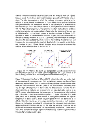
Figure 16. Molar fraction of methane and hydrogen at the pre-reformer outlet in
AOGR mode with varying GHSV at recycling ratio of 0.5. x: methane, and
:hydrogen. Calculated equilibrium values are presented with lines.
4.1.3.3 Carbon formation during extended holds
The pre-reformer also operated in selected conditions for longer time (see Table
4) to investigate possible carbon formation in the pre-reformer or change of cata-
lyst performance. For this purpose, the pre-reformer outlet temperature, gas com-
position and pressure drop over the catalyst and filter were monitored during the
hold. Additionally, after each hold, the set-up was flushed with nitrogen and air and
the CO and CO2 fraction at the set-up outlet was monitored to detect oxidation of
possible carbon deposits. It should be noted that carbon is present at the thermo-
dynamics equilibrium for all the conditions tested in Table 4 (see Figure 13).
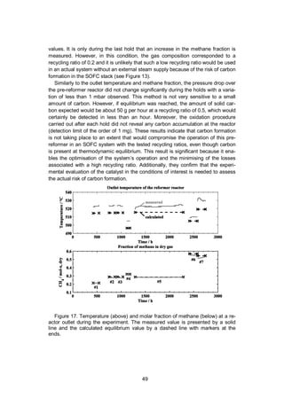
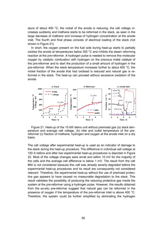
The measured and calculated pre-reformer outlet temperature and methane
fraction during the long-term holds are illustrated in Figure 17. It shows that there
are no significant changes in outlet temperature and composition during the differ-
ent holds. Moreover, the measured values are close to the calculated equilibrium](https://image.slidesharecdn.com/a969d065-d741-4ce2-b38e-5ab0f6e7f2cd-160206144007/85/Thomann2015-dissertation-49-320.jpg)
![50
The aim of this study was to generate the results necessary for the implementation
of an AOGR loop in a 10 kW SOFC system. The main results are that the outlet
gas of the tested pre-reformer and catalyst reach thermodynamic equilibrium more
readily in AOGR conditions compared to SR conditions. No deviation from equilib-
rium was observed with a GHSV of 35,000 h-1
and a recycling ratio of 0.5. Lastly,
carbon formation was not observed during long-term holds (up to 1000 h), despite
carbon being stable at equilibrium in the tested conditions. Therefore, the pre-
reformer and catalyst are considered suitable for implementation in a 10 kW sys-
tem including an AOGR loop.
4.2 Generation of anode protective gas with the system pre-
reformer (Publication IV)
4.2.1 Background
Commonly, SOFC anodes are made of a nickel cermet, where the particles of
nickel are in their metallic form during operation. However, nickel can oxidise if the
stack is hot (> ca. 300 °C) and no reducing gas is fed to the anode. The oxidation
of nickel is very detrimental because it causes a loss of catalyst activity and a
volume increase. Even if the nickel can be reduced again, the volume change
causes mechanical stress and affects the durability of the stack [103]. Tolerance
to reoxidation cycles depends on the microstructure and mechanical properties of
the cells, and efforts are made to develop cells with improved tolerance [104,105].
Alternatively, it is possible to design and operate the BoP components of the
SOFC system to avoid the conditions leading to nickel oxidation; in other words, to
ensure that there is a reducing atmosphere when the stack is above ca. 300 °C. A
critical time is the heat-up of the system, which might last several hours from room
temperature to operating temperature (600–800 °C) in order to keep the thermal
gradient and thermal stresses at an acceptable level. Nickel cermet anode was
observed to start to oxidise at temperatures as low as 290 °C [106] and the oxida-
tion kinetics increases with temperature [107]. Air can be present on the anode
side because of the transport from the cathode to the anode side through the
electrolyte or stack seals [108] and air might have migrated to the anode side from
the exhaust when the system was shut down. Therefore, a forced flow of reducing
protective gas is necessary during heat-up to displace the oxygen and maintain
reducing conditions at the anode.
As explained in Section 4.1, SOFC systems that include an AOGR loop achieve
higher efficiencies and potentially simpler design compared to an SOFC system
without AOGR [109]. However, the AOGR loop needs to be operating during the
heat-up phase in order to heat up all the system components. As a consequence,
the air that leaks to the anode side is force-fed back to the pre-reformer inlet,
which increases the risk of anode reoxidation.](https://image.slidesharecdn.com/a969d065-d741-4ce2-b38e-5ab0f6e7f2cd-160206144007/85/Thomann2015-dissertation-51-320.jpg)
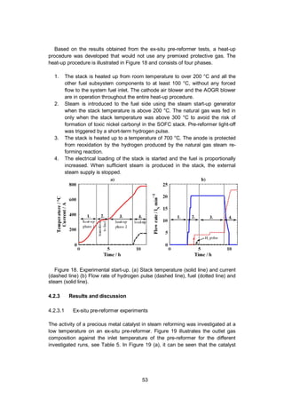
![51
The simplest and safest way to protect the anode during heat-up consists of us-
ing premixed protective gas such as 4%-vol hydrogen in nitrogen. This approach
is not practical for commercial applications because such premixed protective gas
is expensive and due to the lengthy heat-up time, a relatively large amount is
needed. For example, five cylinders of 50 L at 200 bars would be needed to heat
up and start up the 10 kW demonstration unit [43]. Lastly, the protective gas cylin-
ders require space and their replacement and logistics add up to the operation and
maintenance costs. There is therefore a clear incentive to produce such protective
gas within the SOFC system and it can be accomplished by reforming natural gas
in the pre-reformer by providing the steam with the start-up steam generator. The
challenge consists of operating the pre-reformer at a sufficiently high temperature
for the catalyst to be active for steam reforming while avoiding carbon deposition
in the pre-reformer and at the anode during heat-up. Additionally, carbon-
containing species can form nickel carbonyl at the anode below 230 °C according
to reference [105] and the toxicity of this gas is extremely high (the lowest pub-
lished lethal concentration for humans is 30 ppm for 30 min [110,111]; therefore,
the conditions for its formation should be strictly avoided.
Publication IV presents a study aiming at developing a method to heat up the
10 kW demonstration unit without premixed protective gas using natural gas and
steam. Firstly, ex-situ experiments were conducted on a pre-reformer test bench.
The aim of these experiments was to realise the suitable operating parameters of
a pre-reformer at low temperature (<500 °C) in a system with an AOGR loop and
air leakage (i.e. forced oxygen supply to the fuel system). Secondly, the results of
the ex-situ experiments were used to develop a safe heat-up procedure for a 10
kW SOFC system without the use of premixed protective gas. A series of heat-up
cycles were performed on the SOFC system and the performance of the stack
was investigated after each heat-up. Several authors have investigated the heat-
up of an SOFC by modelling [103,112,112-114], but at the time of writing, no ex-
perimental work describing the heat-up of a planar SOFC system with AOGR had
been published previously.
4.2.2 Experimental
4.2.2.1 Ex-situ pre-reformer experiments
The ex-situ experiments were performed on a pre-reformer test bench described
in Figure 11 in Section 4.1.2. The aim of these experiments was to assess the
activity of a precious metal monolith catalyst at low temperature in natural gas
steam reforming. The light-off temperature was determined by the pre-reformer
inlet gas temperature at which the pre-reformer starts to convert methane to hy-
drogen according to the steam reforming reaction (Equation 4).
The gas outlet composition was monitored continuously with an online gas
analysis equipment (IR-based for CH4, thermal conductivity for H2 and paramag-](https://image.slidesharecdn.com/a969d065-d741-4ce2-b38e-5ab0f6e7f2cd-160206144007/85/Thomann2015-dissertation-52-320.jpg)
![52
netic for O2, Sick Maihak S700 series). The analyser results should be used to
evaluate trends rather as quantitative measurements because of the different
channels’ cross-sensitivity. The temperature of the inlet gas was ramped up from
200 to 550 °C at a rate of about 2 °C min-1
. The GHSV of the pre-reformer was
about 32,000 h-1
. The investigated inlet gas flows are listed in Table 5. These
conditions are relevant to the gas composition of an SOFC system using AOGR,
when the steam and fuel supply have just been initiated and the temperature is too
low to expect reforming activity in the pre-reformer or in the stack. Without reform-
ing, the gas in the recirculation loop consists of natural gas, steam and the air
originating from stack leakages. The gas composition in run 1 includes only natu-
ral gas (98% methane), steam and nitrogen. This is the zero-leakage case. In runs
2–7, a small fraction of air was added to simulate the effect of air leakage on the
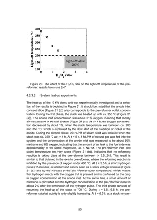
activity of the pre-reformer. In runs 3–7, hydrogen was added with varying H2/O2
ratio from 0 to 4 according to Equation 19.
O2 + 2H2 2 H2O (19)
Nitrogen was added to all runs because a sufficient flow of carrier gas is needed to
operate the steam evaporator and mixer (CEM-303, Bronkhorst). Nitrogen is not
expected to react in the tested conditions.
Table 5. Test gas mixtures used for determining the light-off temperature.
Run 1 2 3 4 5 6 7
Gas
flow /
NLPM
NG 0.5 0.5 0.5 0.5 0.5 0.5 0.5
H2O 10 10 10 10 10 10 10
N2 10 10 10 10 10 10 10
H2 - - 0.2 0.05 0.1 0.15 0.4
Air - 0.5 0.5 0.5 0.5 0.5 0.5
H2/O2 0 2 0.5 1 1.5 4
4.2.2.2 System heat-up experiment
The experiments at system level were realised with the 10 kW demo unit, which is
described in Section 2.5 and illustrated in Figure 2. The system included a 10 kW
stack consisting of 64 anode-supported cells (Versa Power Systems [115]). The
heat needed for the system heat-up was primarily provided by the electrical heater
located at the stack air inlet inside the module, and secondarily heat-up was as-
sisted using an electric heater in the AOGR loop.](https://image.slidesharecdn.com/a969d065-d741-4ce2-b38e-5ab0f6e7f2cd-160206144007/85/Thomann2015-dissertation-53-320.jpg)
![58
5. Performance and material compatibility of
hybrid seals (Publication V and VI)
5.1 Background
Compressive seals composed of mica-type paper have been investigated for
SOFC stack applications [32,35,36]. They have the advantages of having good
thermal cycling capability and being easy to handle during stack assembly [116].
However, they exhibit a relatively high leak rate, principally due to the presence of
interfacial leak paths between the seal and adjacent stack components [37]. For
this reason, they require high compressive stresses (usually at least 2 MPa) to
decrease the extent of these interfacial leak paths for adequate sealing perfor-
mance [35,36,117]. For example, in Publication I, the stack had a cell footprint of
100 cm2
and the applied load on the stack was about 2000 kg, corresponding to
about 4 MPa on the seals. Compression is needed in SOFC stacks to ensure
adequate sealing performance when using compressive seals and good electrical
contact between cells and interconnects. There are multiple benefits to reducing
the compression requirement for the stack, such as reducing the compression
system size and its complexity. Additionally, the compression rods usually need to
go through the stack insulation; therefore, the thinner the rods, the smaller the
heat loss. A smaller compression also enables the use of thinner and less robust
stack components. This means that there are clear benefits to decreasing the
compression stress needed on compressive seals, while retaining the easy han-
dling and assembly of this type of seal.
To overcome the drawbacks of the compressive seals, hybrid seal concepts
have been developed. The principle is to have a core made of compressible mate-
rials sandwiched between layers of compliant materials that would block the inter-
facial leak paths. Thus, the hybrid seal inherits its mechanical properties from the
compressible core but exhibits a low leak rate, even at lower compression stress-
es. This enables the compressible core to deform in response to thermo-
mechanical stresses without causing the failure of the seal. The hybrid seal con-
cept has been investigated by Chou et al. using different micas for the compressi-
ble core and glass or silver foil as compliant layers [118-124].](https://image.slidesharecdn.com/a969d065-d741-4ce2-b38e-5ab0f6e7f2cd-160206144007/85/Thomann2015-dissertation-59-320.jpg)
![59
In addition, it is essential that the sealing materials exhibit limited material inter-
actions with the other SOFC stack components to ensure sufficient stack durabil-
ity. Sealing material interaction studies have previously been published in the
literature, on pure ceramic glass seals [62,125] or on compressible seals
[126,127]. They observed different forms of accelerated corrosion that all took
place preferentially at the three-phase interface sealing material/interconnect
steel/air. Chou et al. presented a post-experimental analysis of a stack using hy-
brid seals [128]. They concluded that material interaction was limited and that their
material selection for the seal and interconnect material was suitable for long-term
operation. However, the three-phase interfaces between seal/interconnect/gas
were not discussed.
The work presented here contributes to the field of sealing solutions for SOFC
by presenting the hybrid seal development at VTT Technical Research Centre of
Finland. The sealing solution uses Thermiculite 866 [129] as a compressible core
coated with glass using an organic carrier. The advantages of using Thermiculite
866 over traditional mica-type paper are its improved gas tightness, because of
the presence of steatite filler between the vermiculite platelets, and its superior
compressibility [35]. The method presented here enables easy stack manufactur-
ing because the seal can be coated beforehand, cut to shape and handled in the
same way as traditional compressible gaskets. The organic carrier present in the
glass coating is burned out in the first heat-up and the remaining glass forms a
thin conformable interlayer between the seal core and adjacent stack components.
The major advantage of the conformable core is also its ability to compensate for
manufacturing tolerances of the adjacent components. Publication V presents the
manufacturing method of the coated seals and the results from ex-situ leakage
tests. The possible material interactions between seals and adjacent components
have been investigated in Publication VI, where a post-experimental analysis of an
SOFC stack using hybrid seals is detailed. The stack operated for 1800 h at 700
°C. The in-situ nature of the experiment provides exposure conditions to the seals
and interconnects that are more relevant to stack operation compared to ex-situ
experiments.
5.2 Experimental
5.2.1 Ex-situ leak rate measurement
The improvement brought about by adding compliant glass layers to compressive
sealing materials was evaluated by leak rate measurements of seal samples made
of Thermiculite 866 (Flexitallic Ltd) material, either uncoated or coated with glass
layers. Thermiculite 866 is a commercial compressive material composed of ver-
miculite and steatite. The materials of the seal were selected to target operation at
700 °C. The glass used was a commercial glass with a softening temperature of
650 °C to obtain a compliant layer.](https://image.slidesharecdn.com/a969d065-d741-4ce2-b38e-5ab0f6e7f2cd-160206144007/85/Thomann2015-dissertation-60-320.jpg)
![61
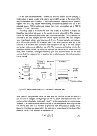
where is the combined volume of the vessel and the sample line, is the tem-
perature of the gas in the volume and Tntp and pntp are normal temperature and
pressure. This method was used to measure the leak rates of Thermiculite 866,
either uncoated or glass-coated.
5.2.2 Stack testing
Hybrid seals were tested in a single-cell stack in order to observe material interac-
tions between seal materials and other stack components during operation. The
stack used a cross-flow configuration. Its metallic components were made of
Crofer 22 APU (ThyssenKrupp). The anode-supported cell was provided by El-
cogen AS and its dimension was 100 mm x 100 mm. Hybrid seals were used for
all seals located between Crofer 22 APU plates and are made with Thermiculite
866 between two glass tapes of 220 µm green thickness. The glass used is a
commercial product from Schott (GM31107), which belongs to the system MO (M
= Mg, Ca)-Al2O3-BaO-SiO2-B2O3 [130]. The Thermiculite 866 is composed in near-
ly equal amount of vermiculite and steatite, the compositions of which are [(K, Mg,
Fe)3(Si,Al)4O10(OH)2] and [(Mg3Si4(OH)2] respectively. The seal between the cell
electrolyte and Crofer 22 APU plate was made of a glass tape without Thermiculite
866. Forty kilograms of weight was added on the stack, which corresponds to a
compressive stress on the seal of ca. 0.1 MPa, assuming all the weight was car-
ried by the seals and not by the cell.
Dry hydrogen and dry air (ca. 0.1%-vol water) were used as fuel and oxidant.
Pure hydrogen exposes the seals to a worst-case condition as the leak rate
through the hybrid seal increases with the concentration of hydrogen as discussed
in Section 5.3. The stack was operated at 700 °C for 1800 h. The average current
density was 0.2 A cm-2
and fuel utilisation and air utilisation were both 18%. The
hydrogen cross leak value was calculated from the relative humidity at the cathode
outlet according to the following equation.
= ,
( ,
) (21)
where ,
is the steam molar fraction at the cathode outlet, ,
is the cathode
air inlet flow, is the current drawn from the stack, and is the Faradic constant.
These calculations are based on the assumption that the different leak rates are
small compared to the cathode air flow.
After the test, the stack was mounted in epoxy resin and a cross-section sample
was extracted near the air outlet for SEM and EDS analysis.](https://image.slidesharecdn.com/a969d065-d741-4ce2-b38e-5ab0f6e7f2cd-160206144007/85/Thomann2015-dissertation-62-320.jpg)
![62
5.3 Results and discussion
The leak rate of seals made of Thermiculite 866 and glass-coated Thermiculite
866 were investigated in order to assess the improvement brought by the addition
of a compliant glass layer between the Thermiculite 866 and the adjacent sealing
surfaces. The leak rates of seals were studied as a function of the pressure differ-
ence across the seal and gas composition. In addition, a stack using a hybrid seal
was assembled, tested and post-experimental microscopy analysis was conducted
to study possible material interactions between seal materials and other stack
components.
The leak rates as a function of pressure at compression stress of 0.1 and 0.4
MPa are detailed in Figure 24. The Thermiculite 866 was coated by wet spraying
and the glass coating after heat treatment was about 10 µm. It can be seen that
coating the Thermiculite 866 with glass decreases the leak rate, especially at low
compressive stress. At low compressive stress and with a pressure difference of
20 mbar, the leak rate of the coated Thermiculite 866 is about 0.4 ml (m min)-1
,
which is a reduction of about 85% compared to the uncoated one (2.7 ml (m min)-1
).
The allowable leak rate in an SOFC stack is specific to the design of the stack and
its operation conditions. However, it is common sense to strive to develop a seal
with the lowest leak rate at low compression stress to limit the fuel loss that limits
the SOFC efficiency, and to decrease the risk of local oxidation of the nickel due to
air leakage to the anode side. The results presented here are coherent with find-
ings in the literature, although direct comparisons are difficult due to different con-
ditions used. Chou et al. reported leak rates below 1 ml (m min)-1
using hybrid
seals made of mica paper coated with glass at compressive stresses of 0.04–0.7
MPa [118,121,131].](https://image.slidesharecdn.com/a969d065-d741-4ce2-b38e-5ab0f6e7f2cd-160206144007/85/Thomann2015-dissertation-63-320.jpg)
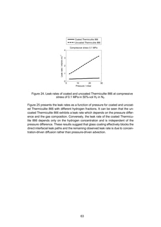
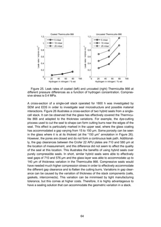
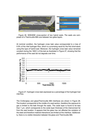
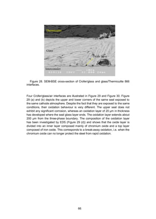
![67
Figure 29. SEM-BSE cross-sections of two Crofer/glass/air interfaces (a and b)
that are both exposed to cathode atmosphere. Magnified view of cross-section (c).
Similarly, Figure 30 depicts the three-phase interfaces of two different seals but
which are exposed to the same air exhaust atmosphere from the air manifold. Also
in this case, one interface (Figure 30 (a)) exhibits no significant oxidation, whereas
a 20 µm-thick oxidation layer can be seen on the steel at the three-phase inter-
face. Accelerated oxidation was also found further in the air manifold towards the
stack air outlet. The oxide layer was thickest 5 mm away from the air manifold
seals, where its thickness reached 120 µm (picture not shown). However, corro-
sion in the manifold of the thick endplate is not critical for stack performance.
There can be different causes for accelerated oxidation of the interconnect
stainless steel. Chromium evaporation is enhanced in the presence of water va-
pour [91]. The water vapour concentration can be locally higher due to a hydrogen
leak into the air atmosphere. However, this is not the case here, because there is
air on both sides of the seals where accelerated oxidation was found. The heavy
oxidation that was found deep in the manifold could be attributed to the presence
of lubricant from machining. The endplates were lubricated during machining and
were subsequently heat-treated (800 °C for 12 hours), polished and only then
cleaned in a laboratory dishwasher and wiped with ethanol-impregnated tissues.
However, it is difficult to remove lubricant or residue from burned lubricant from
the narrow manifolds. This hypothesis is supported by the fact that the heaviest
oxidation was found deep in the manifold, away from the seals. Lastly, the corro-
sion could be attributed to the transport of elements from the glass or the Ther-
miculite 866 to the stainless steel, where they could promote rapid corrosion.](https://image.slidesharecdn.com/a969d065-d741-4ce2-b38e-5ab0f6e7f2cd-160206144007/85/Thomann2015-dissertation-68-320.jpg)
![68
However, if material interaction was the corrosion mechanism, one would expect it
to happen systematically like in [126,127], which is not the case here.
Figure 30. SEM-BSE cross-sections of two Crofer/glass/air interfaces (a and b)
that are both exposed to the atmosphere of the air exhaust manifold.
Bram et al. also found accelerated oxidation in their work on material interaction
between Thermiculite 866 and Crofer 22 APU (no glass used) [127]. They ex-
posed their sample in ambient air at 600 °C for 400 h, which resulted in a very
thick oxide layer (80–100 µm) that extended more than one mm away from the
Thermiculite 866. They attributed the corrosion to an increase of water vapour
content due to the dehydration of vermiculite and the decomposition of steatite.
Wiener et al. also conducted research on the material interaction between Crofer
22 APU and Thermiculite 866 [126]. They exposed their Thermiculite material to
800 °C for 400 h in ambient air and also found accelerated oxidation. Their oxide
layer was about 20 µm in thickness near the seal material. They explained the
oxidation behaviour by the transport of magnesium from the steatite contained in
the Thermiculite 866.
The most likely reason for the observed accelerated corrosion in the tested
stack was attributed to the contamination from lubricant that was not properly
removed during stack assembly. However, material interaction between the glass
and the Thermiculite 866 cannot be ruled out. The main risks associated with
oxidation on the interconnect in the vicinity of the seals is either the formation of
porous oxidation product all the way through the 0.2 mm interconnect or that the
oxidation product forms a conductive bridge between two interconnects, resulting
in short-circuiting. However, in our case the extent of corrosion is rather limited
after 1800 h. Corrosion was only found at the three-phase interface between
glass, steel and air, which is consistent with the results of several previous study
[62,125-127]. Therefore, the author recommends that the three-phase interface
should always be included in material interaction studies between seals and inter-
connects.
The last interfaces investigated were the Crofer/glass/humid hydrogen inter-
face, illustrated in Figure 31, and the glass/YSZ-electrolyte interface in Figure 32.
The Crofer 22 APU oxide layer is below 1 µm next to the glass seal and no visible
interaction is visible between the glass and the electrolyte material. In short, no](https://image.slidesharecdn.com/a969d065-d741-4ce2-b38e-5ab0f6e7f2cd-160206144007/85/Thomann2015-dissertation-69-320.jpg)
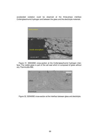
![70
6. Summary and conclusions
SOFC systems are expected to play an important role in the power generation
sector due to their advantages in terms of high efficiency, fuel flexibility, modularity
and very low emissions. However, their high cost remains a burden delaying their
market entry. In order to drive their cost down, their durability must be improved
and system complexity needs to be reduced. The work presented in this disserta-
tion addresses these two challenges by the prevention of chromium poisoning of
the cathode, by demonstrating the possibility to decrease the complexity of the
fuel processing subsystem and by the development of a performant and durable
type of seal.
Chromium poisoning of the cathode causes a degradation of its performance
and it is seen as a major issue limiting the durability of SOFC. A protective coating
solution was developed to limit chromium transport from the stainless steel inter-
connect to the cathode and by the development of a method to quantify the
amount of chromium species originating from BoP components.
Protective MnCo2O4 and MnCo1.8Fe0.2O4 coatings were manufactured on SOFC
interconnect steel by High Velocity Oxy Fuel spraying coating. The coating effec-
tively reduced the oxidation rate of the steel substrate in a high-temperature expo-
sure test. The ASR was measured from coated samples and showed that the ASR
did not exhibit degradation during the 1000 h test at 700 °C. The suitability of the
coating solution was further assessed by performing a post-experimental analysis
of a single-cell stack with a coated interconnect that was operated for 6000 h. It
confirmed that the coating effectively reduced the oxidation of the interconnect and
that the coating did not exhibit cracks or open porosity. Additionally, chromium
could not be detected in the coating, suggesting that the chromium diffusion
through the coating was sufficiently low. A low concentration of chromium was
detected in the SOFC cathode. However, the uncoated steel manifold and piping
upstream of the stack are also known to be a source of volatile chromium and are
likely to be the source of the chromium found in the cathode. Overall, the coating
developed is promising in terms of improving the durability of SOFC stacks by
preventing interconnect oxidation and chromium poisoning of the cathode. The
suitability of the coating should be further assessed in accelerated ageing stack
tests with humidified air because humidity is known to increase the evaporation
rate of chromium from stainless steel [91]. Additionally, electrochemical imped-](https://image.slidesharecdn.com/a969d065-d741-4ce2-b38e-5ab0f6e7f2cd-160206144007/85/Thomann2015-dissertation-71-320.jpg)
![71
ance spectroscopy should be performed during future stack tests to follow the
different contributions to the ASR behaviour during ageing. Obviously, adding any
type of coating increases the cost associated with the SOFC stack, but coatings
that effectively reduces oxidation of the steel allow the use of cheaper grade steel
such as AISI441 (EN 1.4509) [132]. Using a cheaper grade of steel is likely to
offset the cost associated with the coating to some extent.
The findings of Publication I suggested that the stainless steel components up-
stream of the cathode are a potential source of volatile chromium. To gain insight
into this contamination source, a method for quantifying chromium evaporation
from BoP component was developed and evaluated on a stainless steel pipe in
Publication II. The principle of the method is to collect volatile chromium species
by sampling hot air directly from a BoP component through a denuder tube coated
with sodium carbonate. The chromium species react with the sodium carbonate
coating, which is then dissolved and its chromium content analysed by ICP-MS.
The developed method proved to be an effective tool because its results were
found to be coherent with thermodynamics data from the literature and it yielded
repeatable results. These results confirmed that stainless steel BoP components
are a source of volatile chromium that can poison the cathode of SOFC. There-
fore, future research should address the issue of reducing chromium transport
from the hot stainless steel BoP component to the cathode. The experimental set-
up is designed in a way that enables its implementation after a BoP component,
such as a heat exchanger or at various places within an SOFC system. This
makes the assessment of local chromium concentration possible at the stack air
inlet or outlet. Therefore, the method enables identification of the major chromium
sources of the system that can contaminate the SOFC cathode and is a tool for
assessing the effectiveness of solutions such as protective coatings, surface
treatments, chromium trap, and material selection to mitigate chromium transport
from BoP components to the cathode.
Two simplifications of the fuel subsystem are proposed in this dissertation. The
first is to eliminate the external water supply during SOFC operation. A steam
supply is needed for the steam reforming reaction taking place in the fuel pro-
cessing subsystem. The steam can either be supplied externally, which requires a
water inlet and an evaporator or it can be supplied by recycling the steam-rich
anode off-gas, which simplifies the system. Recycling the anode off-gas has been
extensively studied because it can also improve electrical efficiency of SOFC
system, but most of the publications focus on simulation work. However, using
anode off-gas recycling increases the risk of carbon formation in the pre-reformer
at low recycling ratios and its effect on the activity of a precious metal catalyst has
not been published in the literature before Publication III. In Publication III, a com-
mercial precious metal catalyst was tested in steam reforming conditions and in
simulated anode off-gas recycling (AOGR) conditions. It was found that the cata-
lyst is more active in AOGR mode for the evaluated conditions, therefore the pre-
reformer dimension can be reduced if AOGR is used in a system instead of sup-
plying the water externally. Additionally, long-term tests demonstrated that the
tested catalyst did not form carbon to an extent that would threaten SOFC system](https://image.slidesharecdn.com/a969d065-d741-4ce2-b38e-5ab0f6e7f2cd-160206144007/85/Thomann2015-dissertation-72-320.jpg)
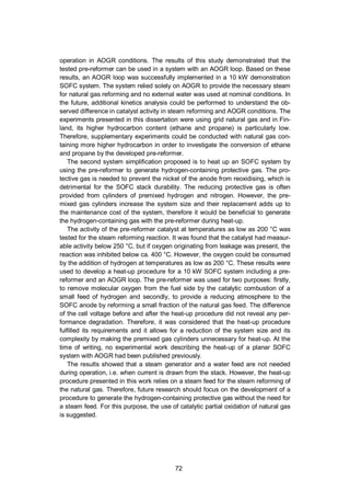
![73
A method for producing hybrid seals consisting of a compressible core coated
with compliant glass was presented in Publication V. The aim of this development
was to achieve low leak rate at low compression stresses. The novelty of the hy-
brid seals investigated in this dissertation is in the core material chosen that con-
tains a steatite filler between vermiculite platelets, which results in improved gas
tightness and superior compressibility. The developed solution exhibited a leak
rate of about 0.4 ml (min m)-1
at 20 mbar pressure difference using a compressive
stress of 0.1 MPa. This is an 85% reduction compared to uncoated Thermiculite
866. The leak rate performance of the developed seal was considered very prom-
ising. The coated Thermiculite 866 could be handled in exactly the same way as
uncoated gasket, thus enabling a simple stack assembling method. Using the
developed hybrid seals instead of compressive seals allows a significant reduction
in the compression need on the stack, which enables the simplification of the stack
compression system.
While the leak rate performance of the developed hybrid seal makes it an attrac-
tive sealing solution, the durability of the SOFC stack requires limited material inter-
actions between the materials of the hybrid seals and other stack components dur-
ing operation. For this purpose, a post-experimental analysis was performed on a
stack using hybrid seals after 1800 h of operation (Publication VI). Different locations
inside the stack were investigated. No corrosion could be found at the two-phase
interfaces such as Crofer/glass, glass/electrolyte and glass/Thermiculite 866. The
three-phase interfaces between Crofer/glass/hydrogen exhibited no corrosion,
whereas interfaces corresponding to Crofer/glass/air exhibited some non-systematic
corrosion. The possible reasons for the corrosion discovered were discussed and
the most likely was the contamination from lubricant that was not properly removed
during stack assembly.
The developed hybrid seal can be used together with the coated interconnect
used in Publication I. However the coating should only be applied where it will be
exposed to oxidative atmosphere (cathode side). The reason for that is that the
reductive atmosphere of the anode is likely to reduce the coating to its metallic
form and to make it porous.
Further research should focus on validating the hypothesis concerning the cor-
rosion found near the hybrid seals in air atmosphere. Additionally, the long-term
suitability of the hybrid seal materials should be investigated either in longer-term
stack tests or by using accelerated ageing conditions such as increasing the air
humidity content to 1…3%. Moreover, tests should be performed to compare the
durability of glass and hybrid seals after numerous thermal cycles as it is known
that thermal cycling is more critical towards durability than steady conditions.
The performance of the developed seal are very promising in terms of leak rate
and material compatibility and the results presented in this section led to the
commercialisation of the developed seal by Flexitallic under the brand “Thermicu-
lite 866 LS”, which is a glass-coated version of the Thermiculite 866 product
[1,133].](https://image.slidesharecdn.com/a969d065-d741-4ce2-b38e-5ab0f6e7f2cd-160206144007/85/Thomann2015-dissertation-74-320.jpg)
![74
SOFCs have demonstrated very good performance in terms of electrical effi-
ciency, which makes them a promising technology for the power generation sec-
tor. At the same time, SOFCs need to show rapid technological progress towards
commercialization in order to sustain investment in research and development
effort. The main obstacle is their high cost: SOFC stacks are expensive and their
lifetime is limited due to degradation. Additionally, system BoP components are
costly, because many of these components are not found off-the-shelf or produced
in small series. There is no doubt that costs will be decreased by economies of
scale when SOFCs are mass produced. However, scientific research has a key
role to play in reducing the cost of SOFCs. Important topics are cost-effective
solutions to improve SOFC durability. In the field of interconnect, coating methods
suitable for mass production should be investigated. Additionally, the protective
coating should enable using standard ferritic stainless steel grades that are much
cheaper than alloys specifically design for SOFCs. An example of such progress is
the roll-to-roll coating method of Sandvik [134]. On the system level, BoP compo-
nents development include the integration of the catalytic reactor and the heat
exchanger. For example, Lee et al. presented the development of a heat ex-
changer, with channels catalytically active for steam reforming and others for after-
burner of the anode off-gas [135]. Other simplifications concern the instrumenta-
tion of the system. For example, stack temperature is difficult to measure. Howev-
er, the maximum stack temperature could be estimated by accurate data-based
models, making direct measurement unnecessary [136].](https://image.slidesharecdn.com/a969d065-d741-4ce2-b38e-5ab0f6e7f2cd-160206144007/85/Thomann2015-dissertation-75-320.jpg)
![75
References
[1] Flexitallic Ltd., Thermiculite ® 866 / 866 LS, 2014, Last accessed 08.01.2015
2015, http://www.flexitallicsofc.com/downloads/thermiculite866.pdf.
[2] Intergouvernmental panel on climate change - IPCC, Fifth Assessment Report
(AR5), Cambridge University Press, Cambridge, United Kingdom and New York,
NY, USA, 2014.
[3] European Environment Agency, Annual European Union Greenhouse Gas
Inventory 1990–2012 and Inventory Report 2014, Publications Office of the Euro-
pean Union, Luxembourg, 2014.
[4] European Environment Agency, EEA Greenhouse gas - Data viewer, 2015,
Last accessed 16.01 2015, http://www.eea.europa.eu/data-and-maps/data/data-
viewers/greenhouse-gases-viewer.
[5] P. Capros, A. De Vita, N. Tasios, D. Papadopoulos, P. Siskos, E. Apostolaki,
M. Zampara, L. Paroussos, K. Fragiadakis, N. Kouvaritakis, L. Höglund-Isaksson,
W. Winiwarter, P. Purohit, H. Böttcher, S. Frank, P. Havlik, M. Gusti, H.P. Witzke,
EU Energy, Transport and GHG Emissions, Trends to 2050. Publications office of
the European Union, Luxembourg, 2013.
[6] L. Chick, M. Weimar, G. Whyatt, M. Powell, The Case for Natural Gas Fueled
Solid Oxide Fuel Cell Power Systems for Distributed Generation, Fuel Cells. 15.1
(2015) 49-60.
[7] S.C. Singhal, Solid oxide fuel cells for stationary, mobile, and military applica-
tions, Solid State Ionics. 152-153 (2002) 405-410.
[8] R. Payne, J. Love, M. Kah, Generating Electricity at 60% Electrical Efficiency
from 1-2 kWe SOFC Products, ECS Trans. 25 (2009) 231-239.
[9] K. Sasaki, K. Watanabe, K. Shiosaki, K. Susuki, Y. Teraoka, Multi-fuel capabil-
ity of solid oxide fuel cells, J Electroceram. 13 (2004) 669-675.
[10] K. Eguchi, H. Kojo, T. Takeguchi, R. Kikuchi, K. Sasaki, Fuel flexibility in pow-
er generation by solid oxide fuel cells, Solid State Ionics. 152-153 (2002) 411-416.
[11] G. Gahleitner, Hydrogen from renewable electricity: An international review of
power-to-gas pilot plants for stationary applications, Int J Hydrogen Energy. 38
(2013) 2039-2061.
[12] E4tech, The Fuel Cell Industry Review 2014, Lausanne, Switzerland, 2014.](https://image.slidesharecdn.com/a969d065-d741-4ce2-b38e-5ab0f6e7f2cd-160206144007/85/Thomann2015-dissertation-76-320.jpg)
![76
[13] Fuel cell and hydrogen joint undertaking (FCH JU), Multi Annual Implementa-
tion Plan 2008-2013. 2011.
[14] H. Yokokawa, H. Tu, B. Iwanschitz, A. Mai, Fundamental mechanisms limiting
solid oxide fuel cell durability, J. Power Sources. 182 (2008) 400-412.
[15] R.M. Ormerod, Solid oxide fuel cells, Chem. Soc. Rev. 32 (2003) 17-28.
[16] S.J. Skinner, Recent advances in Perovskite-type materials for solid oxide fuel
cell cathodes, International Journal of Inorganic Materials. 3 (2001) 113-121.
[17] D.J.L. Brett, A. Atkinson, N.P. Brandon, S.J. Skinner, Intermediate tempera-
ture solid oxide fuel cells, Chem. Soc. Rev. 37 (2008) 1568-1578.
[18] E. Konysheva, H. Penkalla, E. Wessel, J. Mertens, U. Seeling, L. Singheiser,
K. Hilpert, Chromium poisoning of perovskite cathodes by the ODS alloy Cr5Fe1
Y2 O3 and the high chromium ferritic steel Crofer22APU, J. Electrochem. Soc.
153 (2006) A765-A773.
[19] K. Hilpert, D. Das, M. Miller, D.H. Peck, R. Weiß, Chromium vapor species
over solid oxide fuel cell interconnect materials and their potential for degradation
processes, J. Electrochem. Soc. 143 (1996) 3642-3647.
[20] J. Wu, X. Liu, Recent Development of SOFC Metallic Interconnect, J. Mater.
Sci. Technol. 26 (2010) 293-305.
[21] J.W. Fergus, Metallic interconnects for solid oxide fuel cells, Materials Sci-
ence and Engineering A. 397 (2005) 271-283.
[22] W.Z. Zhu, S.C. Deevi, Development of interconnect materials for solid oxide
fuel cells, Mater. Sci. Eng. A. 348 (2003) 227-243.
[23] N. Shaigan, W. Qu, D.G. Ivey, W. Chen, A review of recent progress in coat-
ings, surface modifications and alloy developments for solid oxide fuel cell ferritic
stainless steel interconnects, J. Power Sources. 195 (2010) 1529-1542.
[24] Z. Yang, K.S. Weil, D.M. Paxton, J.W. Stevenson, Selection and Evaluation of
Heat-Resistant Alloys for SOFC Interconnect Applications, J. Electrochem. Soc.
150 (2003).
[25] P.D. Jablonski, C.J. Cowen, J.S. Sears, Exploration of alloy 441 chemistry for
solid oxide fuel cell interconnect application, J. Power Sources. 195 (2010) 813-
820.
[26] Y. Chou, J.W. Stevenson, J. Choi, Long-term evaluation of solid oxide fuel cell
candidate materials in a 3-cell generic stack test fixture, part III: Stability and mi-](https://image.slidesharecdn.com/a969d065-d741-4ce2-b38e-5ab0f6e7f2cd-160206144007/85/Thomann2015-dissertation-77-320.jpg)
![77
crostructure of Ce-(Mn,Co)-spinel coating, AISI441 interconnect, alumina coating,
cathode and anode, J. Power Sources. 257 (2014) 444-453.
[27] Z. Yang, G.-G. Xia, C.-M. Wang, Z. Nie, J. Templeton, J.W. Stevenson, P.
Singh, Investigation of iron-chromium-niobium-titanium ferritic stainless steel for
solid oxide fuel cell interconnect applications, J. Power Sources. 183 (2008) 660-
667.
[28] M.W. Lundberg, R. Berger, J. Westlinder, N. Folkeson, H. Holmberg, Novel
multilayered PVD-coating in a roll to roll mass production process, ECS Transac-
tions. 57 (2013) 2203-2208.
[29] J.W. Stevenson, Z.G. Yang, G.G. Xia, Z. Nie, J.D. Templeton, Long-term
oxidation behavior of spinel-coated ferritic stainless steel for solid oxide fuel cell
interconnect applications, J. Power Sources. 231 (2013) 256-263.
[30] J.W. Fergus, Sealants for solid oxide fuel cells, J. Power Sources. 147 (2005)
46-57.
[31] K. Weil, The state-of-the-art in sealing technology for solid oxide fuel cells,
JOM. 58 (2006) 37-44.
[32] Z. Wuillemin, N. Autissier, M. Nakajo, M. Luong, J. Van Herle, D. Favrat,
Modeling and study of the influence of sealing on a solid oxide fuel cell, J. Fuel
Cell Sci. Technol. 5 (2008).
[33] Y. Chou, J.W. Stevenson, R.N. Gow, Novel alkaline earth silicate sealing
glass for SOFC: Part II. Sealing and interfacial microstructure, J. Power Sources.
170 (2007) 395-400.
[34] A. Shyam, R. Trejo, D. McClurg, A. Ladouceur, M. Kirkham, X. Song, J.
Howe, E. Lara-Curzio, Microstructural evolution in two alkali multicomponent sili-
cate glasses as a result of long-term exposure to solid oxide fuel cell environ-
ments, J. Mater. Sci. 48 (2013) 5880-5898.
[35] M. Rautanen, O. Himanen, V. Saarinen, J. Kiviaho, Compression properties
and leakage tests of mica-based seals for SOFC stacks, Fuel Cells. 9 (2009) 753-
759.
[36] S.P. Simner, J.W. Stevenson, Compressive mica seals for SOFC applica-
tions, J. Power Sources. 102 (2001) 310-316.
[37] Y.-S. Chou, J.W. Stevenson, L.A. Chick, Ultra-low leak rate of hybrid com-
pressive mica seals for solid oxide fuel cells, J. Power Sources. 112 (2002) 130-
136.](https://image.slidesharecdn.com/a969d065-d741-4ce2-b38e-5ab0f6e7f2cd-160206144007/85/Thomann2015-dissertation-78-320.jpg)
![78
[38] Y.-S. Chou, J.W. Stevenson, L.A. Chick, Novel compressive mica seals with
metallic interlayers for solid oxide fuel cell applications, J Am Ceram Soc. 86
(2003) 1003-1007.
[39] D. Mogensen, J.-D. Grunwaldt, P.V. Hendriksen, K. Dam-Johansen, J.U.
Nielsen, Internal steam reforming in solid oxide fuel cells: Status and opportunities
of kinetic studies and their impact on modelling, J. Power Sources. 196 (2011) 25-
38.
[40] Y. Yi, A.D. Rao, J. Brouwer, G.S. Samuelsen, Fuel flexibility study of an inte-
grated 25 kW SOFC reformer system, J. Power Sources. 144 (2005) 67-76.
[41] S.L. Douvartzides, F.A. Coutelieris, A.K. Demin, P.E. Tsiakaras, Fuel options
for solid oxide fuel cells: A thermodynamic analysis, AIChE J. 49 (2003) 248-257.
[42] R.-U. Dietrich, J. Oelze, A. Lindermeir, C. Spieker, C. Spitta, M. Steffen, Pow-
er generation from biogas using SOFC - Results for a 1kWe demonstration unit,
Fuel Cells. 14 (2014) 239-250.
[43] M. Halinen, M. Rautanen, J. Saarinen, J. Pennanen, A. Pohjoranta, J. Ki-
viaho, M. Pastula, B. Nuttall, C. Rankin, B. Borglum, Performance of a 10 kW
SOFC Demonstration Unit, ECS Transactions. 35 (2011) 113-120.
[44] K. Ahmed, J. Gamman, K. Föger, Demonstration of LPG-fueled solid oxide
fuel cell systems, Solid State Ionics. 152-153 (2002) 485-492.
[45] Y. Du, D. Cui, K. Reifsnider, Characterization of propane-fueled SOFC porta-
ble power systems, ECS Transactions. 35 (2011) 167-178.
[46] P. Leone, A. Lanzini, G.A. Ortigoza-Villalba, R. Borchiellini, Operation of a
solid oxide fuel cell under direct internal reforming of liquid fuels, Chem. Eng. J.
191 (2012) 349-355.
[47] M. Rautanen, M. Halinen, M. Noponen, K. Koskela, H. Vesala, J. Kiviaho,
Experimental study of an SOFC stack operated with autothermally reformed diesel
fuel, Fuel Cells. 13 (2013) 304-308.
[48] D. Shekhawat, D.A. Berry, J.J. Spivey, Fuel Cells: Technologies for Fuel
Processing, Elsevier Ltd., Oxford, UK, 2011.
[49] Union Gas, Chemical Composition of Natural Gas, 2015, Last accessed 01.22
2015, http://www.uniongas.com/about-us/about-natural-gas/Chemical-
Composition-of-Natural-Gas.
[50] Energinet.dk, Vis gaskvalitet, 2013, Last accessed 01.22 2015,
http://energinet.dk/DA/GAS/Gasdata-og-kvalitet/Gaskvalitet/Sider/Vis-
gaskvalitet.aspx?Visning=aarsgennemsnit.](https://image.slidesharecdn.com/a969d065-d741-4ce2-b38e-5ab0f6e7f2cd-160206144007/85/Thomann2015-dissertation-79-320.jpg)
![79
[51] Gasum Oy, Natural Gas Composition Yearly Report, 2012.
[52] R. Peters, R. Dahl, U. Klüttgen, C. Palm, D. Stolten, Internal reforming of
methane in solid oxide fuel cell systems, J. Power Sources. 106 (2002) 238-244.
[53] S. McIntosh, R.J. Gorte, Direct hydrocarbon solid oxide fuel cells, Chem. Rev.
104 (2004) 4845-4865.
[54] J.N. Armor, The multiple roles for catalysis in the production of H2, Applied
Catalysis A: General. 176 (1999) 159-176.
[55] L. Blum, E. Riensche, FUEL CELLS – SOLID OXIDE FUEL CELLS | Sys-
tems, in: J. Garche (Ed.), Encyclopedia of Electrochemical Power Sources, Else-
vier, Amsterdam, 2009, pp. 99-119.
[56] P. Gannon, R. Amendola, High-temperature, dual-atmosphere corrosion of
solid-oxide fuel cell interconnects, JOM. 64 (2012) 1470-1476.
[57] H. Tu, U. Stimming, Advances, aging mechanisms and lifetime in solid-oxide
fuel cells, J. Power Sources. 127 (2004) 284-293.
[58] M. Stanislowski, E. Wessel, K. Hilpert, T. Markus, L. Singheiser, Chromium
vaporization from high-temperature alloys, J. Electrochem. Soc. 154 (2007).
[59] M.C. Tucker, H. Kurokawa, C.P. Jacobson, L.C. De Jonghe, S.J. Visco, A
fundamental study of chromium deposition on solid oxide fuel cell cathode materi-
als, J. Power Sources. 160 (2006) 130-138.
[60] J.A. Schuler, H. Yokokawa, C.F. Calderone, Q. Jeangros, Z. Wuillemin, A.
Hessler-Wyser, J. Van Herle, Combined Cr and S poisoning in solid oxide fuel cell
cathodes, J. Power Sources. 201 (2012) 112-120.
[61] J.W. Fergus, Effect of cathode and electrolyte transport properties on chromi-
um poisoning in solid oxide fuel cells, Int J Hydrogen Energy. 32 (2007) 3664-
3671.
[62] N.H. Menzler, P. Batfalsky, L. Blum, M. Bram, S.M. Groß, V.A.C. Haanappel,
J. Malzbender, V. Shemet, R.W. Steinbrech, I. Vinke, Studies of material interac-
tion after long-term stack operation, Fuel Cells. 7 (2007) 356-363.
[63] Y. Larring, T. Norby, Spinel and perovskite functional layers between Plansee
metallic interconnect (Cr-5 wt % Fe-1 wt % Y2O3) and ceramic
(La0.85Sr0.15)0.91MnO3 cathode materials for solid oxide fuel cells, J. Electro-
chem. Soc. 147 (2000) 3251-3256.
[64] J.W. Fergus, Synergism in the design of interconnect alloy–coating combina-
tions solid for oxide fuel cells, Scr. Mater. 65 (2011) 73-77.](https://image.slidesharecdn.com/a969d065-d741-4ce2-b38e-5ab0f6e7f2cd-160206144007/85/Thomann2015-dissertation-80-320.jpg)
![80
[65] X. Montero, N. Jordán, J. Pirón-Abellán, F. Tietz, D. Stöver, M. Cassir, I. Vil-
larreal, Spinel and perovskite protection layers between crofer22APU and La
0.8Sr0.2FeO3 cathode materials for SOFC interconnects, J. Electrochem. Soc.
156 (2009) B188-B196.
[66] J. Puranen, J. Lagerbom, L. Hyvärinen, M. Kylmälahti, O. Himanen, M. Pihlat-
ie, J. Kiviaho, P. Vuoristo, The structure and properties of plasma sprayed iron
oxide doped manganese cobalt oxide spinel coatings for SOFC metallic intercon-
nectors, J. Therm. Spray Technol. 20 (2011) 154-159.
[67] X. Chen, P.Y. Hou, C.P. Jacobson, S.J. Visco, L.C. De Jonghe, Protective
coating on stainless steel interconnect for SOFCs: oxidation kinetics and electrical
properties, Solid State Ionics. 176 (2005) 425-433.
[68] Z. Yang, G. Xia, G.D. Maupin, J.W. Stevenson, Conductive protection layers
on oxidation resistant alloys for SOFC interconnect applications, Surf. Coat. Tech-
nol. 201 (2006) 4476-4483.
[69] A. Balland, P. Gannon, M. Deibert, S. Chevalier, G. Caboche, S. Fontana,
Investigation of La2O3 and/or (Co,Mn)3O4 deposits on Crofer22APU for the
SOFC interconnect application, Surf. Coat. Technol. 203 (2009) 3291-3296.
[70] Y. Fang, C. Wu, X. Duan, S. Wang, Y. Chen, High-temperature oxidation
process analysis of MnCo2O4 coating on Fe–21Cr alloy, Int J Hydrogen Energy.
36 (2011) 5611-5616.
[71] J. Puranen, J. Lagerbom, L. Hyvärinen, T. Mäntylä, E. Levänen, M. Kylmälah-
ti, P. Vuoristo, Formation and structure of plasma sprayed manganese-cobalt
spinel coatings on preheated metallic interconnector plates, Surf. Coat. Technol.
205 (2010) 1029-1033.
[72] K. Uusi-Esko, E.-L. Rautama, M. Laitinen, T. Sajavaara, M. Karppinen, Con-
trol of oxygen nonstoichiometry and magnetic property of MnCo 2O 4 thin films
grown by atomic layer deposition, Chem. Mater. 22 (2010) 6297-6300.
[73] L. Mikkelsen, M. Chen, P.V. Hendriksen, Å. Persson, N. Pryds, K. Rodrigo,
Deposition of La0.8Sr0.2Cr0.97V0.03O3 and MnCr2O4 thin films on ferritic alloy
for solid oxide fuel cell application, Surf. Coat. Technol. 202 (2007) 1262-1266.
[74] M.J. Lewis, J.H. Zhu, A process to synthesize (Mn,Co) 3 O 4 spinel coatings
for protecting SOFC interconnect alloys, Electrochem. Solid-State Lett. 14 (2011)
B9-B12.
[75] V.I. Gorokhovsky, P.E. Gannon, M.C. Deibert, R.J. Smith, A. Kayani, M.
Kopczyk, D. Vanvorous, Z. Yang, J.W. Stevenson, S. Visco, C. Jacobson, H.
Kurokawa, S.W. Sofie, Deposition and evaluation of protective PVD coatings on
ferritic stainless steel SOFC interconnects, J. Electrochem. Soc. 153 (2006)
A1886-A1893.](https://image.slidesharecdn.com/a969d065-d741-4ce2-b38e-5ab0f6e7f2cd-160206144007/85/Thomann2015-dissertation-81-320.jpg)
![81
[76] L. Pawlowski, Thermal Spraying Techniques, The Science and Engineering of
Thermal Spray Coatings, John Wiley & Sons, Ltd, 2008, pp. 67-113.
[77] Z. Yang, G.-G. Xia, X.-H. Li, J.W. Stevenson, (Mn,Co)3O4 spinel coatings on
ferritic stainless steels for SOFC interconnect applications, Int J Hydrogen Energy.
32 (2007) 3648-3654.
[78] L. Mikkelsen, K. Neufeld, P.V. Hendriksen, Interface Resistance Between
FeCr Interconnects and La0.85Sr0.15Mn1,1O3, ECS Transactions. 25 (2009)
1429.
[79] Z. Yang, J.S. Hardy, M.S. Walker, G. Xia, S.P. Simner, J.W. Stevenson,
Structure and conductivity of thermally grown scales on ferritic Fe-Cr-Mn steel for
SOFC interconnect applications, J. Electrochem. Soc. 151 (2004) A1825-A1831.
[80] J.A. Schuler, Z. Wuillemin, A. Hessler-Wyser, C. Comminges, N.Y. Steiner, J.
Van Herle, Cr-poisoning in (La,Sr)(Co,Fe)O 3 cathodes after 10,000 h SOFC stack
testing, J. Power Sources. 211 (2012) 177-183.
[81] O. Thomann, M. Pihlatie, J.A. Schuler, O. Himanen, J. Kiviaho, Method for
measuring chromium evaporation from SOFC balance-of-plant components, Elec-
trochem. Solid-State Lett. 15 (2012) B35-B37.
[82] Z. Wuillemin, N. Nakajoa, A. Müllera, A. Schuler, S. Diethelm, J. Van herle, D.
Favrat, Locally-resolved study of degradation in a SOFC, ECS Trans. 25 (2009)
457-466.
[83] J.A. Schuler, C. Gehrig, Z. Wuillemin, A.J. Schuler, J. Wochele, C. Ludwig, A.
Hessler-Wyser, J. Van Herle, Air side contamination in Solid Oxide Fuel Cell stack
testing, J. Power Sources. 196 (2011) 7225-7231.
[84] K. Gerdes, C. Johnson, Surface Scale Formation on Solid Oxide Fuel Cell
Proximal Balance of Plant Components, Journal of Fuel Cell Sci. & Tech. vol. 6
(2009).
[85] M. Stanislowski, E. Wessel, T. Markus, L. Singheiser, W.J. Quadakkers,
Chromium vaporization from alumina-forming and aluminized alloys, Solid State
Ionics. 179 (2008) 2406-2415.
[86] D. Chatterjee, S. Biswas, Development of chromium barrier coatings for solid
oxide fuel cells, Int J Hydrogen Energy. 36 (2011) 4530-4539.
[87] J.A. Schuler, A.J. Schuler, D. Penner, A. Hessler-Wyser, C. Ludwig, J. Van
Herle, Mitigating Cr Contamination by Hot Air Filtering in Solid Oxide Fuel Cells,
Electrochemical and Solid-State Letters. 14 (2011).](https://image.slidesharecdn.com/a969d065-d741-4ce2-b38e-5ab0f6e7f2cd-160206144007/85/Thomann2015-dissertation-82-320.jpg)
![82
[88] C. Key, J. Eziashi, J. Froitzheim, R. Amendola, R. Smith, P. Gannon, Methods
to Quantify Reactive Chromium Vaporization from Solid Oxide Fuel Cell Intercon-
nects, Journal of The Electrochemical Society. 161 (2014) C373-C381.
[89] J. Froitzheim, H. Ravash, E. Larsson, L.G. Johansson, J.E. Svensson, Inves-
tigation of chromium volatilization from FeCr interconnects by a denuder tech-
nique, J. Electrochem. Soc. 157 (2010) B1295-B1300.
[90] M. Casteel, P. Willson, T. Goren, P. O'Brien, D. Lewis, Novel Method for
Measuring Chromia Evaporation from SOFC Interconnect Materials, ECS Trans.
25 (2009) 1423.
[91] C. Gindorf, L. Singheiser, K. Hilpert, Vaporisation of chromia in humid air, J.
Phys. Chem. Solids. 66 (2005) 384-387.
[92] Outotec, HSC Chemistry, 6.12 (2007).
[93] Sandvik, Sandvik 253MA, Last accessed 11/16 2011,
http://www.smt.sandvik.com/en/materials-center/material-datasheets/tube-and-
pipe-seamless/sandvik-253-ma/.
[94] E. Riensche, J. Meusinger, U. Stimming, G. Unverzagt, Optimization of a 200
kW SOFC cogeneration power plant. Part II: Variation of the flowsheet, J. Power
Sources. 71 (1998) 306-314.
[95] R.-U. Dietrich, J. Oelze, A. Lindermeir, C. Spitta, M. Steffen, T. Küster, S.
Chen, C. Schlitzberger, R. Leithner, Efficiency gain of solid oxide fuel cell systems
by using anode offgas recycle - Results for a small scale propane driven unit, J.
Power Sources. 196 (2011) 7152-7160.
[96] M. Noponen, M. Halinen, J. Saarinen, J. Kiviaho, Experimental study of anode
gas recycling on efficiency of SOFC, ECS Transactions. 5 (2007) 545-551.
[97] D. Larrain, J. Van herle, D. Favrat, Simulation of SOFC stack and repeat
elements including interconnect degradation and anode reoxidation risk, J. Power
Sources. 161 (2006) 392-403.
[98] M.P. Heddrich, M. Jahn, A. Michaelis, R. Näke, A. Weder, SOFC system
design using ideal efficiency modeling - Model and experimental implementation,
Fuel Cells. 13 (2013) 612-622.
[99] R. Peters, E. Riensche, P. Cremer, Pre-reforming of natural gas in solid oxide
fuel-cell systems, J. Power Sources. 86 (2000) 432-441.
[100] A. Nummela, M. Noponen, Experimental Study on Effects of Anode Recircu-
lation to Pre-Reforming of Natural Gas, European Fuel Cell Forum. B0301 (2009).](https://image.slidesharecdn.com/a969d065-d741-4ce2-b38e-5ab0f6e7f2cd-160206144007/85/Thomann2015-dissertation-83-320.jpg)
![83
[101] D.G. Goodwin, An open-source, extensible software suite for CVD process
simulation, In Proceedings of CVD XVI and EuroCVD 14, M. Allendorf, F. Maury,
and E. Teyssandier, Eds, PV 2003-2008.
[102] G.P. Smith, GRI-MECH 3.0, 2009, Last accessed 03.04 2015,
http://combustion.berkeley.edu/gri-mech/.
[103] A. Selimovic, M. Kemm, T. Torisson, M. Assadi, Steady state and transient
thermal stress analysis in planar solid oxide fuel cells, J. Power Sources. 145
(2005) 463-469.
[104] M. Pihlatie, T. Ramos, A. Kaiser, Testing and improving the redox stability of
Ni-based solid oxide fuel cells, J. Power Sources. 193 (2009) 322-330.
[105] A. Wood, M. Pastula, D. Waldbilig, D.G. Ivey, Initial testing of solutions to
redox problems with anode-supported SOFC, J. Electrochem. Soc. 153 (2006)
A1929-A1934.
[106] Q. Jeangros, A. Faes, J.B. Wagner, T.W. Hansen, U. Aschauer, J. Van
herle, A. Hessler-Wyser, R.E. Dunin-Borkowski, In situ redox cycle of a nickel–
YSZ fuel cell anode in an environmental transmission electron microscope, Acta
Materialia. 58 (2010) 4578-4589.
[107] M. Pihlatie, A. Kaiser, M. Mogensen, Redox stability of SOFC: Thermal anal-
ysis of Ni-YSZ composites, Solid State Ionics. 180 (2009) 1100-1112.
[108] J.F.B. Rasmussen, P.V. Hendriksen, A. Hagen, Study of internal and exter-
nal leaks in tests of anode-supported SOFCs, Fuel Cells. 8 (2008) 385-393.
[109] R. Peters, R. Deja, L. Blum, J. Pennanen, J. Kiviaho, T. Hakala, Analysis of
solid oxide fuel cell system concepts with anode recycling, Int J Hydrogen Energy.
38 (2013) 6809-6820.
[110] Guidechem.com, Nickel carbonyl(Ni(CO)4), (cas 13463-39-3) msds, 2014,
Last accessed 11/21 2014, http://www.guidechem.com/msds/13463-39-3.html.
[111] Matheson Tri Gas, Material safety data sheet nickel carbonyl, 2008, Last
accessed 03.04 2015, https://www.mathesongas.com/pdfs/msds/MAT16290.pdf.
[112] L. Petruzzi, S. Cocchi, F. Fineschi, A global thermo-electrochemical model
for SOFC systems design and engineering, J. Power Sources. 118 (2003) 96-107.
[113] H. Apfel, M. Rzepka, H. Tu, U. Stimming, Thermal start-up behaviour and
thermal management of SOFC's, J. Power Sources. 154 (2006) 370-378.
[114] D.L. Damm, A.G. Fedorov, Reduced-order transient thermal modeling for
SOFC heating and cooling, J. Power Sources. 159 (2006) 956-967.](https://image.slidesharecdn.com/a969d065-d741-4ce2-b38e-5ab0f6e7f2cd-160206144007/85/Thomann2015-dissertation-84-320.jpg)
![84
[115] B. Borglum, E. Tang, M. Pastula, Development of solid oxide fuel cells at
versa power systems, ECS Transactions. 35 (2011) 63-69.
[116] Y.-S. Chou, J.W. Stevenson, Compressive mica seals for solid oxide fuel
cells, ASM Conference Proceedings: Joining of Advanced and Specialty Materials.
(2005) 132-139.
[117] M. Bram, S. Reckers, P. Drinovac, J. Mönch, R.W. Steinbrech, H.P.
Buchkremer, D. Stöver, Deformation behavior and leakage tests of alternate seal-
ing materials for SOFC stacks, J. Power Sources. 138 (2004) 111-119.
[118] Y.-S. Chou, J.W. Stevenson, L.A. Chick, Ultra-low leak rate of hybrid com-
pressive mica seals for solid oxide fuel cells, J. Power Sources. 112 (2002) 130-
136.
[119] Y.-S. Chou, J.W. Stevenson, L.A. Chick, Novel compressive mica seals with
metallic interlayers for solid oxide fuel cell applications, J Am Ceram Soc. 86
(2003) 1003-1007.
[120] Y. Chou, J.W. Stevenson, Long-term ageing and materials degradation of
hybrid mica compressive seals for solid oxide fuel cells, J. Power Sources. 191
(2009) 384-389.
[121] Y.-S. Chou, J.W. Stevenson, Infiltrated phlogopite micas with superior ther-
mal cycle stability as compressive seals for solid oxide fuel cells, Ceramic Trans-
actions. 161 (2005) 89-98.
[122] Y.-S. Chou, J.W. Stevenson, J. Hardy, P. Singh, Material degradation during
isothermal ageing and thermal cycling of hybrid mica seals under solid oxide fuel
cell exposure conditions, J. Power Sources. 157 (2006) 260-270.
[123] Y.-S. Chou, J.W. Stevenson, Novel infiltrated Phlogopite mica compressive
seals for solid oxide fuel cells, J. Power Sources. 135 (2004) 72-78.
[124] Y.-S. Chou, J.W. Stevenson, P. Singh, Thermal cycle stability of a novel
glass-mica composite seal for solid oxide fuel cells: Effect of glass volume fraction
and stresses, J. Power Sources. 152 (2005) 168-174.
[125] P. Batfalsky, V.A.C. Haanappel, J. Malzbender, N.H. Menzler, V. Shemet,
I.C. Vinke, R.W. Steinbrech, Chemical interaction between glass–ceramic sealants
and interconnect steels in SOFC stacks, J. Power Sources. 155 (2006) 128-137.
[126] F. Wiener, M. Bram, H.-P. Buchkremer, D. Sebold, Chemical interaction
between Crofer 22 APU and mica-based gaskets under simulated SOFC condi-
tions, J. Mater. Sci. 42 (2007) 2643-2651.](https://image.slidesharecdn.com/a969d065-d741-4ce2-b38e-5ab0f6e7f2cd-160206144007/85/Thomann2015-dissertation-85-320.jpg)
![85
[127] M. Bram, L. Niewolak, N. Shah, D. Sebold, H.P. Buchkremer, Interaction of
sealing material mica with interconnect steel for solid oxide fuel cells application at
600 °C, J. Power Sources. 196 (2011) 5889-5896.
[128] Y.-S. Chou, J.W. Stevenson, J.-P. Choi, Long-term evaluation of solid oxide
fuel cell candidate materials in a 3-cell generic short stack fixture, Part II: Sealing
glass stability, microstructure and interfacial reactions, J. Power Sources. 250
(2014) 166-173.
[129] J.R. Hoyes, S. Bond, Gaskets for sealing solid oxide fuel cells, Sealing
Technology. (2007) 11-14.
[130] D. Goedeke, J. Besinger, Y. Pflügler, B. Ruedinger, New Glass Ceramic
Sealants for SOFC, ECS Transactions. 25 (2009) 1483-1490.
[131] Y.-S. Chou, J.W. Stevenson, Novel infiltrated Phlogopite mica compressive
seals for solid oxide fuel cells, J. Power Sources. 135 (2004) 72-78.
[132] J.G. Grolig, J. Froitzheim, J.-E. Svensson, Coated stainless steel 441 as
interconnect material for solid oxide fuel cells: Oxidation performance and chromi-
um evaporation, J. Power Sources. 248 (2014) 1007-1013.
[133] J.R. Hoyes, M. Rautanen, SOFC sealing with thermiculite 866 and thermicu-
lite 866 LS, ECS Transactions. 57 (2013) 2365-2374.
[134] M.W. Lundberg, R. Berger, J. Westlinder, N. Folkeson, H. Holmberg, Novel
multilayered PVD-coating in a roll to roll mass production process, ECS Transac-
tions. 57 (2013) 2203-2208.
[135] K. Lee, J. Yun, K. Ahn, S. Lee, S. Kang, S. Yu, Operational characteristics of
a planar steam reformer thermally coupled with a catalytic burner, Int J Hydrogen
Energy. 38 (2013) 4767-4775.
[136] A. Pohjoranta, M. Halinen, J. Pennanen, J. Kiviaho, Solid oxide fuel cell
stack temperature estimation with data-based modeling - Designed experiments
and parameter identification, J. Power Sources. 277 (2015) 464-473.](https://image.slidesharecdn.com/a969d065-d741-4ce2-b38e-5ab0f6e7f2cd-160206144007/85/Thomann2015-dissertation-86-320.jpg)